2381660X491中文资料
2381 66. 5...1 / PTCCL..H...BE
Vishay BCcomponents
Document Number: 29085For technical questions contact: nlr.europe@https://www.360docs.net/doc/02724077.html,
https://www.360docs.net/doc/02724077.html,
30 to 60 V PTC Thermistors For
Overload Protection
FEATURES
?Wide range of trip and non-trip currents: from 94 mA up to 2 A for the trip current
?Wide range of resistance: from 0.3 ? up to 50 ??Small ratio between trip and non-trip currents (I t /I nt = 1.5 at 25 °C)
?High maximum inrush current
?Excellent long term behaviour, also in humidity
?Leaded parts withstand mechanical stresses and vibration ?UL file E148885 according to XGPU standard UL1434?UL approved PTCs are guaranteed to withstand severe test programs
?Long-life cycle tests (over 5000 trip cycles)?Long-life storage tests (3000 hours at 250 °C)?Electrical cycle tests at low ambient temperatures (- 40 °C or 0 °C)
?Damp-heat and water immersion tests
?Overvoltage tests at up to 200 % of rated voltage
?Component in accordance to RoHS 2002/95/EC and WEEE 2002/96/EC
APPLICATIONS
?Telecommunications ?Automotive systems ?Industrial electronics ?Consumer electronics
?
Electronic data processing
DESCRIPTION
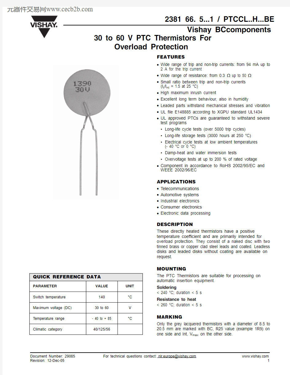
These directly heated thermistors have a positive temperature coefficient and are primarily intended for overload protection. They consist of a naked disc with two tinned brass or copper clad steel leads and coated. Leadless disks and leaded disks without coating are available on request.
MOUNTING
The PTC Thermistors are suitable for processing on automatic insertion equipment.Soldering
< 240 °C; duration < 5 s Resistance to heat < 260 °C; duration < 5 s
MARKING
Only the grey lacquered thermistors with a diameter of 8.5 to 20.5 mm are marked with BC, R25 value (example 1R9) on one side and Int, V max on the other side.
QUICK REFERENCE DATA
PARAMETER
VALUE UNIT Switch temperature 140°C Maximum voltage (DC)30 to 60V Temperature range - 40 to + 85°C
Climatic category
40/125/56
https://www.360docs.net/doc/02724077.html, For technical questions contact: nlr.europe@https://www.360docs.net/doc/02724077.html,
Document Number: 29085
2381 66. 5...1 / PTCCL..H...BE Vishay 30 to 60 V PTC Thermistors For
Overload Protection
Notes
1.The thermistors are clamped at the seating plane.
2.I max is the maximum overload current that may flow through the PTC when it passes from the low ohmic to the high ohmic state.
UL approval: I max *0.85
For bulk parts replace x by “5” and y by “B”.
For taped on reel parts replace it x by “6” and y by “T”.
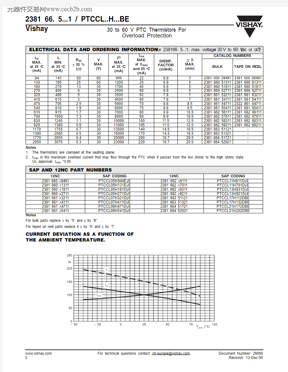
CURRENT DEVIATION AS A FUNCTION OF THE AMBIENT TEMPERATURE.
ELECTRICAL DATA AND ORDERING INFORMATION for 238166. 5...1; max. voltage =30V to 60 V (ac or dc)1)
I nt
MAX.at 25 °C (mA)I t MIN.at 25°C (mA)
R 25± 20 %(?)V MAX.(V)I 2)MAX.at 25°C (mA)I res MAX.at V max and 25°C (mA)DISSIP.FACTOR (mW/K)? D MAX.(mm)CATALOG NUMBERS
BULK TAPE ON REEL 94145506080022 6.952381 660 594912381 660 694911301952560120025 6.952381 660 513112381 660 613111802701330170045 6.952381 660 518112381 660 61811270405630250060 6.952381 660 527112381 660 627113204805303500627.872381 661 532112381 661 632114106153304500657.872381 661 541112381 661 64111470705 2.5305000708.88.52381 661 547112322 661 64711540810 1.9306000758.88.52381 661 554112381 661 65411610915 1.7307000809.910.52381 662 561112381 662 661117001050 1.3308000909.910.52381 662 570112381 662 670118301245 1.1301000010011.512.52381 662 583112381 662 6831192013800.9301100010511.512.52381 662 592112381 662 69211
117017550.7301350014014.516.52381 663 51121-139020850.5301600017014.516.52381 663 51321-177026550.4302000020018.720.52381 664 51721-2050
3075
0.3
30
23000
220
18.7
20.5
2381 664 52021
-
SAP AND 12NC PART NUMBERS
12NC
SAP CODING 12NC
SAP CODING 2381 660 x9491PTCCL05H940EyE 2381 662 x6111PTCCL11H611DyE 2381 660 x1311PTCCL05H131EyE 2381 662 x7011PTCCL11H701DyE 2381 660 x1811PTCCL05H181DyE 2381 662 x8311PTCCL13H831DyE 2381 660 x2711PTCCL05H271DyE 2381 662 x9211PTCCL13H921DyE 2381 661 x3211PTCCL07H321DyE 2381 663 51121PTCCL17H112DBE 2381 661 x4111PTCCL07H411DyE 2381 663 51321PTCCL17H132DBE 2381 661 x4711PTCCL09H471DyE 2381 664 51721PTCCL21H172DBE 2381 661 x5411
PTCCL09H541DyE
2381 664 52021
PTCCL21H202DBE
Document Number: 29085For technical questions contact: nlr.europe@https://www.360docs.net/doc/02724077.html,
https://www.360docs.net/doc/02724077.html,
2381 66. 5...1 / PTCCL..H...BE
30 to 60 V PTC Thermistors For
Overload Protection
Vishay ELECTRICAL CHARACTERISTICS
I MAX AS A FUNCTION OF VOLTAGE.
I max as stated in the Electrical data and ordering information tables, is the maximum overload current that may flow through the PTC when passing from the low ohmic to high ohmic state at rated voltage.
When other voltages are present after tripping, the I max value can be derived from the above I max as a function of voltage graph. Voltages below V rated will allow higher overload currents to pass the PTC.
PTC THERMISTORS IN BULK
COMPONENTS OUTLINE
CODE NUMBER
2381
S.P.Q OUTLINE 660 5...1500Fig. 1a 6...11500Fig. 1b 661 5...1250Fig. 1a 6...11500Fig. 1b 662
5...1250Fig. 1a 66111 - 670111500Fig. 1b 68311 - 69211
750Fig. 1c 663 5 (1200)
Fig. 1a 664
5 (1)
100
Fig. 1a
Fig. 1a
2381 66. 5...1 / PTCCL..H...BE
Vishay 30 to 60 V PTC Thermistors For
Overload Protection
PTC THERMISTORS ON TAPE ON REEL
Fig. 1b
Fig. 1c
TAPE AND REEL ACCORDING TO IEC60286-2 dimensions in millimeters
SYMBOL PARAMETER DIMENSIONS TOLERANCE REMARKS
D d D0
body diameter
lead diameter
feed hole diameter
see table
0.6
4.0
max
± 10 %
± 0.2
F lead to lead distance 5.0+ 0.6
- 0.1guaranteed between component and tape
H0 H2 H3 H4?h
lead wire clinch height
component bottom to seating plane
component top to seating plane
seating plane difference
(left-right lead)
component alignment
16.0
4.0
D + 5
± 0.5
± 1.0
max.
± 0.2
± 2.0
L1lead length20min.
T t
total thinkness
total tape thickness
4.0
0.9
max.
max.with cardboard tape
0.5 ± 0.1
Document Number: 29085For technical questions contact: nlr.europe@https://www.360docs.net/doc/02724077.html,
https://www.360docs.net/doc/02724077.html,
2381 66. 5...1 / PTCCL..H...BE
30 to 60 V PTC Thermistors For
Overload Protection
Vishay REEL SPECIFICATIONS
in millimeters
REEL DIMENSIONS in millimeters
DIAMETER ?
W 1W 2MAX.< 12
42± 15612
46± 1
60
TYPICAL RESISTANCE/TEMPERATURE CHARACTERISTIC
TYPICAL RESISTANCE/TEMPERATURE
CHARACTERISTIC
TYPICAL RESISTANCE/TEMPERATURE CHARACTERISTIC
TYPICAL RESISTANCE/TEMPERATURE CHARACTERISTIC
Legal Disclaimer Notice
Vishay
Notice
Specifications of the products displayed herein are subject to change without notice. Vishay Intertechnology, Inc., or anyone on its behalf, assumes no responsibility or liability for any errors or inaccuracies.
Information contained herein is intended to provide a product description only. No license, express or implied, by estoppel or otherwise, to any intellectual property rights is granted by this document. Except as provided in Vishay's terms and conditions of sale for such products, Vishay assumes no liability whatsoever, and disclaims any express or implied warranty, relating to sale and/or use of Vishay products including liability or warranties relating to fitness for a particular purpose, merchantability, or infringement of any patent, copyright, or other intellectual property right. The products shown herein are not designed for use in medical, life-saving, or life-sustaining applications. Customers using or selling these products for use in such applications do so at their own risk and agree to fully indemnify Vishay for any damages resulting from such improper use or sale.