A calibration-free gaze tracking technique
A Calibration-Free Gaze Tracking Technique
Sheng-Wen Shih and Yu-Te Wu
Department of Computer Science
and Information Engineering National Chi Nan University,545,Taiwan (stone and ytw)@https://www.360docs.net/doc/049071107.html,.tw
Jin Liu
Heinrich-Hertz Institute Berlin, 10587Berlin,Germany
liu@hhi.de
Abstract
We propose a novel method to estimate and track the3-D line of sight of a person based on3-D computer vision techniques.Most of the existing nonintrusive gaze track-ing methods share a common drawback:users have to per-form certain experiments in calibrating the user-dependent parameters before using the gaze tracking systems.These parameters are functions of the radius of the cornea,the position of the pupil,the position of user’s head,etc..Our approach,in contrast,employs multiple cameras and mul-tiple point light sources to estimate the light of sight with-out using any of the user-dependent parameters.As a con-sequence,the users can avoid the inconvenient calibra-tion process which may produce possible calibration errors. Computer simulations have been performed to con?rm the proposed method.
1.Introduction
When we stare at a3-D point,our oculomotor mecha-nism controls our eyes such that the image of the point ap-pears at the fovea region of our eyes.The3-D LoS(Line of Sight)of the eye is a straight line which passes through the 3D point,the fovea spot and the optical center of the eye. The problem of3-D gaze tracking is to determine and track the3-D LoS of a person from the appearance of his eyes and has numerous applications in the area of human com-puter interaction.For example,we can use the gaze point of a man to develop a more ef?cient interface in control-ling computers than the traditional mouse.There are basi-cally three types of gaze tracking techniques:(1)techniques based on re?ected light[1][2][3],(2)techniques based on electric skin potential[4],and(3)techniques based on con-tact lenses[5].Techniques of the?rst type is nonintrusive including limbus tracker,pupil tracker,pupil and cornea re-This work is supported in part by the National Science Council of Taiwan under Grants NSC87-2218-E-260-003.?ection tracker,and Purkinje image tracker.The techniques of the second and the third types are intrusive and will not be discussed in this paper.Most of the existing nonintru-sive gaze tracking methods using light re?ected by different portion of the eye(such as the cornea,the lens,the iris,and the retina)share the common drawback:the users are asked to perform tedious calibration of user-dependent parameters before using the gaze tracking systems.Moreover,most of the methods focused on monocular(2-D)vision techniques and imposed stringent constraints to simplify the3-D gaze tracking problem into a2-D problem.These constraints re-quire the user to hold their head quite still or the apparatus to be?xed relative to the user’s head.
In this paper,we propose a novel method to resolve the user-dependent calibration problem and estimate the3-D line of sight based on3-D computer vision techniques.The estimation theory developed in this work is based on the simpli?ed eye model proposed by Le Grand[6].We show that the line of sight of a user can be directly measured by using multiple cameras and point light sources without using any user-dependent parameters.Therefore,the pro-posed system is calibration-free to the users.
Our method?rst uses the?rst Purkinje images of point light sources to determine the location of the eye by using multiple cameras(refer to section2).The estimated3-D position of the eye and the observed centers of the pupil images are then used to compute the gaze direction of the eye(refer to section3).
https://www.360docs.net/doc/049071107.html,puting Cornea Center From the First
Purkinje Image
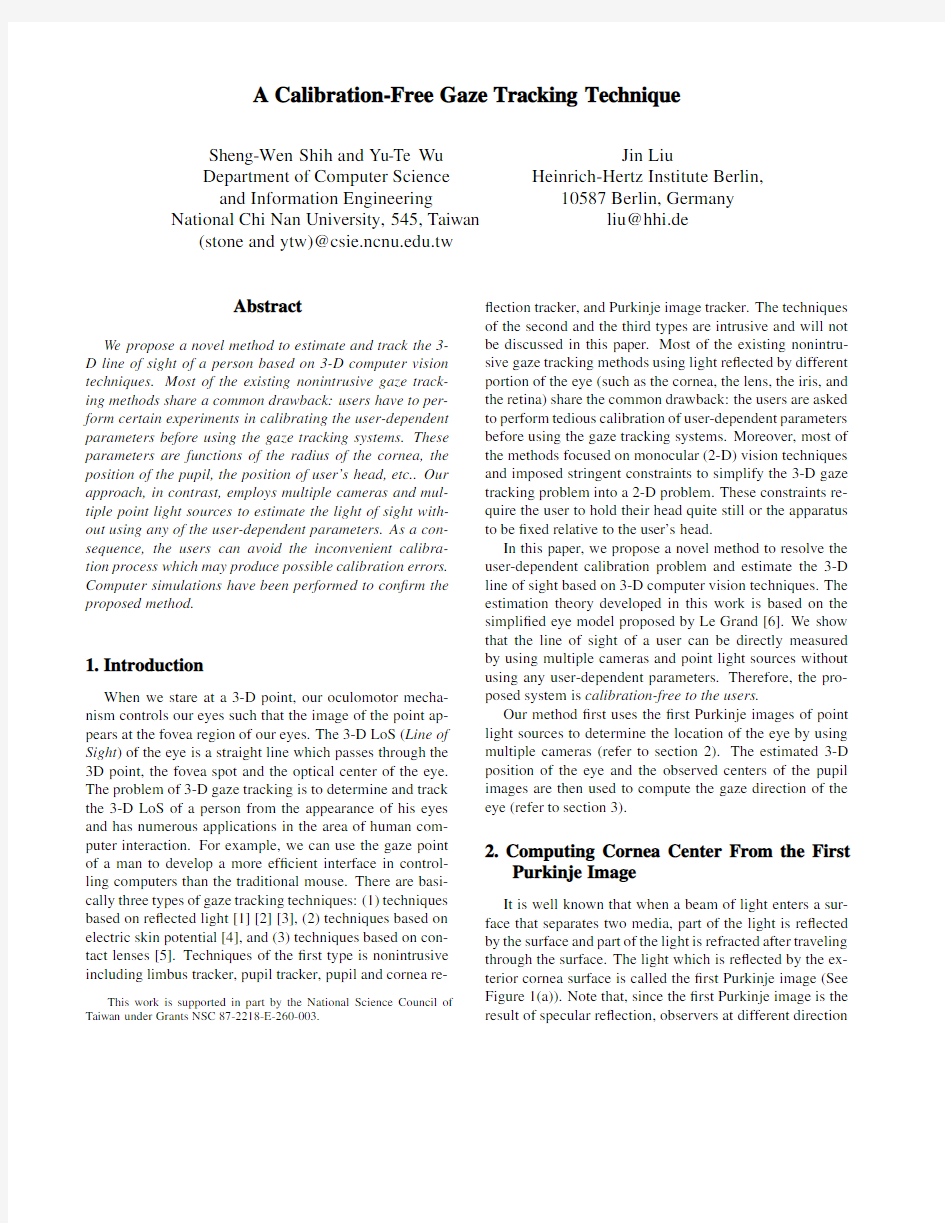
It is well known that when a beam of light enters a sur-face that separates two media,part of the light is re?ected by the surface and part of the light is refracted after traveling through the surface.The light which is re?ected by the ex-terior cornea surface is called the?rst Purkinje image(See Figure1(a)).Note that,since the?rst Purkinje image is the result of specular re?ection,observers at different direction
will observe different images.Figure 1(b)shows the ?rst Purkinje image of an infrared LED (Light Emitting Diode).LEDs are commonly used as the point light sources in gaze tracking systems since it is safe and cost effective.
(b)
Figure 1.The ?rst Purkinje image of an LED.Let denote the optical center of a camera and denote the position of a point light source.Let us assume that the camera parameters and the position of point light source rel-ative to the camera reference frame,denoted by ,have been accurately calibrated (the calibration process is irrele-vant to the users).Given the 2-D point of the ?rst Purkinje
image in the retinal plane,denoted by
,and the cali-brated optical center of the camera,,we can compute the 3-D vector (see Figure 1).
According to the law of re?ection,the location of the point light source,the beams of incident and the re?ected light and the normal vector of the re?ected surface are
coplanar.That is,both the normal vector,
,and the cornea center,,are on the plane
Based on the location of the point light source and its ?rst Purkinje image recorded by a camera,a linear constraint for computing the location of the cornea center can be formu-lated by the following plane equation in the camera coordi-nate system:
(1)
where the normal vector of the planar surface is the cross-product of and and is the vector representing cornea center.If there are point light sources,,,1,2,...,and identi?ed Purkinje im-ages for every point light sources,we will have plane equations with the form of equation (1).However,the solu-tion of these plane equations is not unique.The following proposition summarize this property.
Proposition 1.If the optical center of a camera,,and a
set of the point light sources,
’s,are not collinear,then the solutions to the plane equations in the form of equation (1)is a 3-D line.
Proof.It is obvious that the plane equations is not of full rank because all the planes contains both the optical center of the camera,,and the cornea center,.Furthermore,if there exists two point light sources,and ,such that
and are not collinear,then
and are not collinear;hence,the rank of the plane equations is two.
It follows from Proposition 1that if the cornea radius,,of the user is unknown,gaze tracking systems using one camera can only determine the 3-D direction instead of the 3-D position of the cornea center with respect to the camera reference coordinates.The condition for obtaining a unique solution for the cornea center when the cornea radius is un-known is summarized in the following proposition:Proposition 2.If the cornea radius,,is unknown,then one will have to use at least two cameras and at least two point light sources to recover the 3-D position of the cornea center.Furthermore,in order to provide unique solution for the 3-D cornea center,any of the optical centers of the cameras and the point light sources should not be collinear.
Proof.According to Proposition 1,a 3-D line which con-tains the optical center of the camera and the cornea center
in the camera reference frame can be determined by using a camera and at least two point light sources,where the opti-cal center of the camera and the point light sources are not collinear.When we have two cameras and two point light sources satisfying the non-collinear conditions,we obtain two 3-D line equations;one line passes through the optical center of one camera and through the cornea center and the other line passes through the optical center of the other cam-era and through the cornea center.If the optical centers of the two cameras do not coincide with each other,these two lines intersect at one point,i.e.,the location of the cornea center.
3.Orientation of the 3-D Line of Sight
3.1.Virtual Image of the 3-D Pupil
Our pupil is located inside a convex lens composed of the cornea and the aqueous humor.Due to the refraction of the convex lens,any object point,,inside the cornea has a virtual image,,when it is viewed from an outside camera.For example,it is the virtual image of a pupil,not the pupil itself,that is observed from a camera.
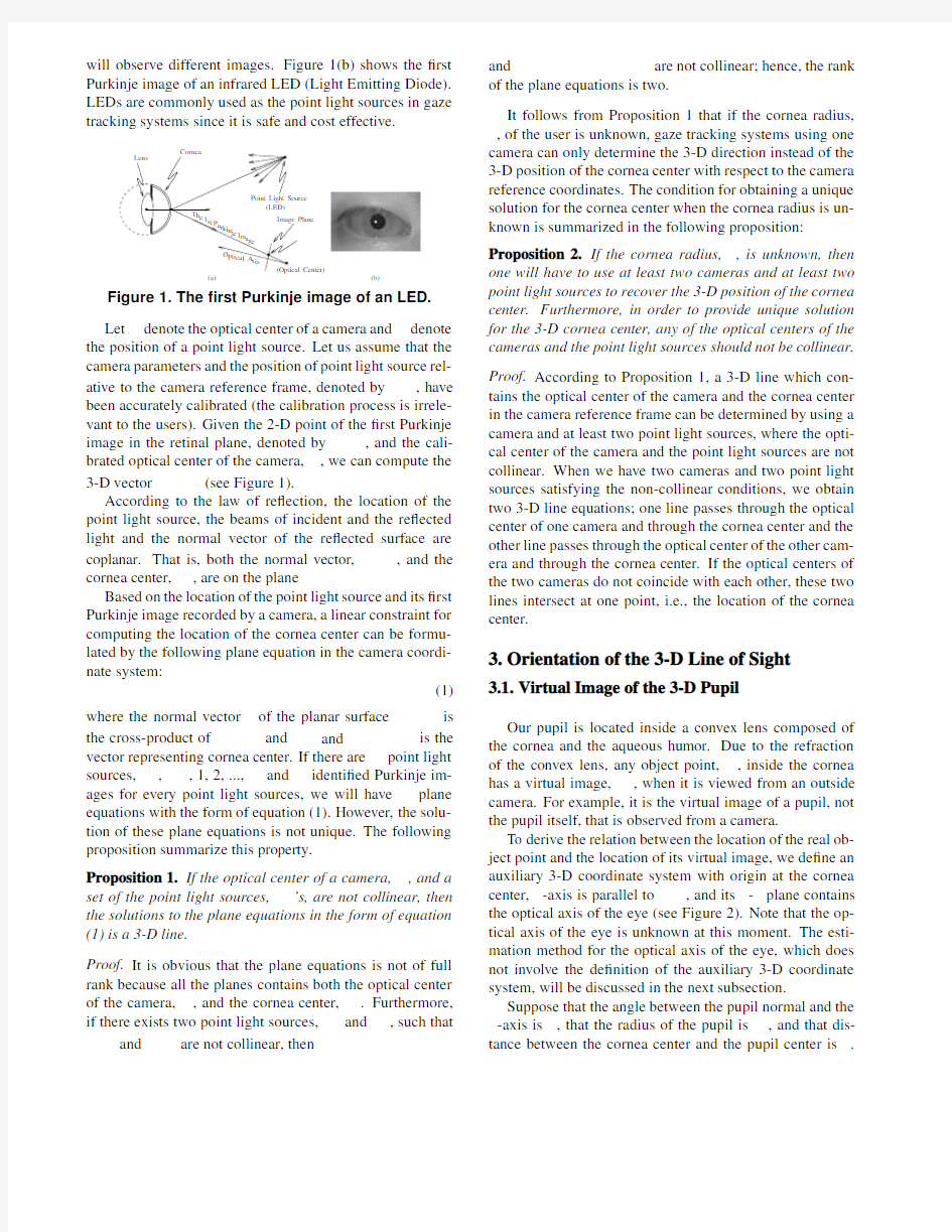
To derive the relation between the location of the real ob-ject point and the location of its virtual image,we de?ne an auxiliary 3-D coordinate system with origin at the cornea
center,-axis is parallel to
,and its -plane contains the optical axis of the eye (see Figure 2).Note that the op-tical axis of the eye is unknown at this moment.The esti-mation method for the optical axis of the eye,which does not involve the de?nition of the auxiliary 3-D coordinate system,will be discussed in the next subsection.
Suppose that the angle between the pupil normal and the -axis is ,that the radius of the pupil is ,and that dis-tance between the cornea center and the pupil center is .
The3-D coordinates of the pupil circular edges can be de-?ned as follows:
(2) where.The coordinates of the virtual pupil image can be computed based on basic geometric optics, and the derived coordinates of the virtual pupil image are given by
(3) where,,,is the refraction index of the cornea,and is the refraction index of the
air.
Figure2.The auxiliary3-D coordinate system
located at the cornea center.
It can be shown that the virtual image of the pupil is still a planar object,and the center of the virtual pupil can be determined by setting to zero in
(4)
Likewise,when is set to zero in equation(2),we obtain the center of the real pupil,, which is on the-plane of the auxiliary3-D coordi-nate system,and the center of the virtual pupil image shown in equation(4)is also on the-plane(because
).It follows that,and the-axis of the auxiliary3-D coordinate system are coplanar.
Suppose that the3-D virtual image of the pupil is recorded on a2-D image by a camera and that from the recorded image,the edge points of the2-D pupil image are found to be,=1,2,...,.Because the center of the3-D virtual pupil image is invisible,its2-D image lo-cation,denoted by,can only be inferred by using’s. Estimation of using is a dif?culty problem because of the nonlinearity of the perspective projection.However,
since the radius of the virtual pupil image is very small com-pared with the distance between the eye and the gaze track-
ing cameras,af?ne projection can be used to accurately de-
scribe the relationship between the3-D virtual pupil image and its projected2-D pupil image.The image location of
the virtual pupil image center,,can be determined by
owing to the linearity of af?ne projec-
tion.After the image location of the virtual pupil image center is determined,we shall discuss the estimation of the
orientation of the LoS in the following subsections.
3.2.Linear Constraint for the Direction of LoS
Because each camera can record only one pupil image,
to determine the3-D position of without knowing the
values of and,we will have to use at least two cameras and will need the following proposition.
Proposition 3.Suppose that a gaze tracking system equipped with at least two cameras has been calibrated so
that the transformation matrices between any two reference
frames of the cameras are known.If the cornea center,,is estimated by using the method described in section2,the3-
D coordinates of with respect to the th camera reference frame coordinates,denoted by,can be computed with
the calibrated transformation matrices.Let the direction of
the center of the virtual pupil image in the th camera ref-erence frame be denoted by which can be estimated by
back-projecting into the3-D space.Given two pairs of ’s and’s,for,where and are not collinear,the gaze direction,de?ned by the vector pointing
from the cornea center toward the real pupil center,can be
determined by solving linear equations.
Proof.Recall that,and are coplanar,where is the3-D vector of the gaze direction in the th cam-era reference frame.If and are not collinear for ,then we can de?ne two planar equations:
,and
,where is the relative orientation matrix between camera reference frames and.These two equations are linear dependent when,,and are coplanar.In this singular case,is coplanar with both and,i.e.,the user is?xating at a point of the line connecting the optical centers of the two cam-eras.Otherwise,the direction of can be determined by solving the above two planar equations.
4.Simulation Results
In the computer simulation,we assumed that a pair of stereo cameras were used for gaze tracking.The focal
lengths of the lenses of both the cameras are75mm,and the vertical and horizontal pixel spacing are all0.01mm. These two simulated cameras were placed at the lower-left and lower-right corners of a simulated17-inch monitor,re-spectively.Two point light sources were used in the sim-ulation.One is placed at the middle location of the stereo cameras,and the other one is placed at150mm above the left camera.The synthesized spherical cornea is located at 450mm in front of the monitor and of the same height as the top edge of the monitor.Radius of the cornea sphere was set to8mm.Refraction index of the cornea,i.e.,,was set to1.336.The distance between the real pupil center and the cornea center was set to5mm.The radius of the pupil circle,,is set to3mm.Images were generated by us-ing true parameters and2-D noise was added for simulating measurement error.
To simulate the head movement of users,the3-D posi-tion of the eye is generated by a3-D random vector whose length varies with a standard deviation of about17.32mm. The camera parameters are generated by a procedure simu-lating camera calibration with200calibration points and a 2-D measurement white Gaussian noise with a standard de-viation of0.1pixels.The positions of the point light sources used for LoS estimation are generated by adding random unit vectors multiplied by0.3mm.
Figure3(a)and(b)show the RMSE(Root-Mean-Square Error)of the estimated cornea position and the estimated gaze direction,respectively.When2-D measurement noise is absent,the estimation error is due to the calibration error. Cornea center error is about0.58mm and gaze direction er-ror is about0.002radians.As the amount of image mea-surement noise increased from0to1.0pixels,the position error increased gradually to about0.88mm.However,the gaze direction error increased more rapidly than the posi-tion estimation error does.This is because that the position of the cornea center is estimated by using stereo vision tech-nique which is very robust,whereas estimation of the gaze direction is related to the2-D line segment connecting the center of the2-D pupil image,and the image location of cornea center,i.e.,the2-D projection of.The length of this line segment is only about several pixels.Figure3(c) shows the mean ratio of the2-D noise and the length of this line segment.When the amount of2-D noise is1pixel,the noise-to-signal ratio is0.2;therefore,estimation of the gaze direction is sensitive to noise.Nevertheless,since the2-D noise is at the order of about0.5pixels which is equivalent to have0.026radians of gaze direction error,the estimation error of the?xation point measured on the monitor screen is about11mm.It is possible to reduce the?xation point error to some extent if the user stares at the point of interest for a while and multiple measurements are performed.
5.Conclusions and Future Work
We have proposed a novel method to estimate the3-D line of sight.Our method employs multiple cameras to de-termine the cornea center and the gaze direction using linear solutions.We have also shown that the suf?cient condition for solving the3-D gaze tracking problem using the pro-posed linear solutions is to use at least two cameras and at least two point light sources.The advantage of using the proposed method is that the user is independent of the calibration process.Simulation results show that the pro-posed method is promising.Our future work is to develop a method for estimating the positions of multiple point light sources and to implement the gaze tracking system based on the proposed method.
References
[1]T.Cornweet and H.Crane,“Accurate two-dimensional eye
tracker using?rst and fourth purkinje images,”Journal of Op-tical Society America,vol.63,no.8,1973.
[2]J.K.P.White,T.E.Hutchinson,and J.M.Carley,“Spa-
tially dynamic calibration of an eye-tracking system,”IEEE Transactions on Systems,Man and Cybernetics,vol.23,no.4, pp.1162–1168,1993.
[3]S.Pastoor,J.Liu,and S.Renault,“An experimental multi-
media system allowing3-d visualization and eye-controlled interaction without user-worn devices,”IEEE Transactions on Multimedia,vol.1,no.1,pp.41–52,1999.
[4]J.Gips,P.Olivieri,and J.Tecce,“Direct control of the com-
puter through electrodes placed around the eyes,”in in the Proceedings of the Fifth International Conference on Human-Computer Interaction,(Elsevier,Orlando,Florida),pp.630–635,1993.
[5]L.Bour,“Dmi-search scleral coil,”Tech.Rep.H2-214,Dept.
of Neurology,Clinical Neurophysiology,Academic Medical Centre,AZUA,Meibergdreef9,1105AZ Amsterdam,Nether-lands,1997.
[6]Y.L.Grand,Light,Color and Vision.Wiley,1957.