日本横河质量流量计RCCx3_GS_EN_ed09

GS 01R4B04-00E-E
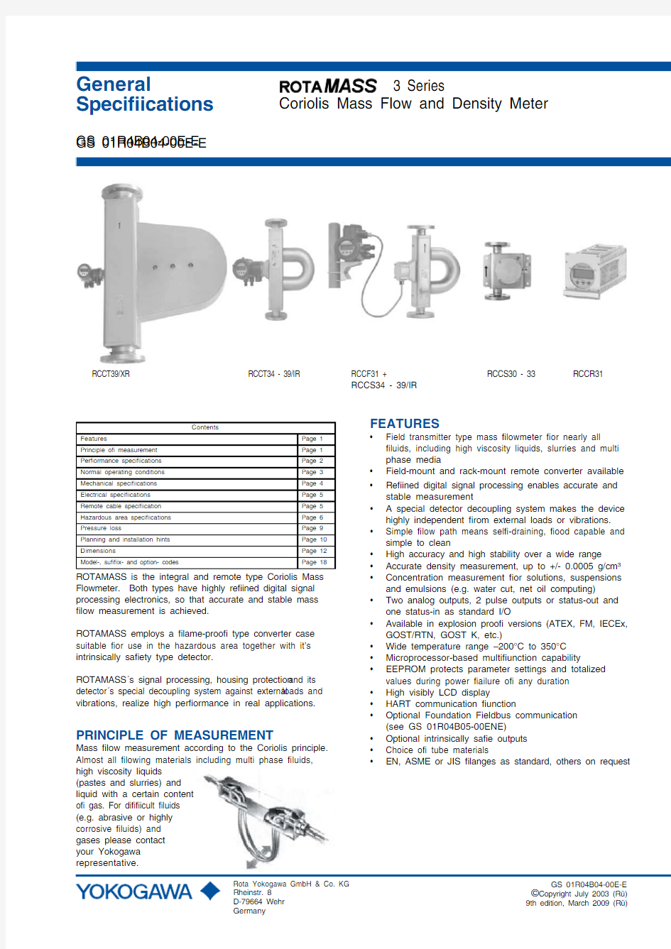
3 Series
Coriolis Mass Flow and Density Meter
GS 01R04B04-00E-E
?Copyright July 2003 (Rü)
9th edition, March 2009 (Rü)
Rota Yokogawa GmbH & Co. KG Rheinstr. 8D-79664 Wehr Germany
General
Specifications
RCCT39/XR RCCT34 - 39/IR RCCF31 + RCCS30 - 33 RCCR31 RCCS34 - 39/IR
ROTAMASS is the integral and remote type Coriolis Mass Flowmeter. Both types have highly refined digital signal processing electronics, so that accurate and stable mass flow measurement is achieved.
ROTAMASS employs a flame-proof type converter case suitable for use in the hazardous area together with it’s intrinsically safety type detector.
ROTAMASS′s signal processing, housing protection and its detector′s special decoupling system against external loads and vibrations, realize high performance in real applications.
FEATURES
? Field transmitter type mass flowmeter for nearly all fluids, including high viscosity liquids, slurries and multi phase media
? Field-mount and rack-mount remote converter available ? Refined digital signal processing enables accurate and stable measurement
? A special detector decoupling system makes the device highly independent from external loads or vibrations.? Simple flow path means self-draining, food capable and simple to clean
? High accuracy and high stability over a wide range ? Accurate density measurement, up to +/- 0.0005 g/cm3? Concentration measurement for solutions, suspensions and emulsions (e.g. water cut, net oil computing)
? Two analog outputs, 2 pulse outputs or status-out and one status-in as standard I/O
?
Available in explosion proof versions (ATEX, FM, IECEx, GOST/RTN, GOST K, etc.)
? Wide temperature range –200°C to 350°C ? Microprocessor-based multifunction capability
? EEPROM protects parameter settings and totalized values during power failure of any duration ? High visibly LCD display
? HART communication function
? Optional Foundation Fieldbus communication (see GS 01R04B05-00ENE)
? Optional intrinsically safe outputs ? Choice of tube materials
?
EN, ASME or JIS flanges as standard, others on request
PRINCIPLE OF MEASUREMENT
Mass flow measurement according to the Coriolis principle. Almost all flowing materials including multi phase fluids, high viscosity liquids (pastes and slurries) and liquid with a certain content of gas. For difficult fluids (e.g. abrasive or highly corrosive fluids) and gases please contact your Yokogawa representative.
GS 01R04B04-00E-E
Contents
Features
Page 1Principle of measurement Page 1Performance specifications Page 2Normal operating conditions Page 3Mechanical specifications Page 4Electrical specifications Page 5Remote cable specification Page 5Hazardous area specifications Page 6Pressure loss
Page 9Planning and installation hints Page 10Dimensions
Page 12Model-, suffix- and option- codes
Page 18
GS 01R04B04-00E-E 9th edition March 05, 2009-00
2
All Rights Reserved. Copyright ? 2003, Rota Yokogawa
Qnom is the water flow rate at about 1 bar pressure drop.
The flowmeter has an automatically low cut at 0.05% of Qnom.
Accuracy mass flow : Liquid : ± 0.1% of flow rate
± ((zero stability) / flow rate*100%)
(refer to table 2) Gas (option /GA) : ± 0.5% of flow rate
± ((zero stability) / flow rate*100%)
(refer to table 2)
Accuracy volume flow :
SQRT ( (mass flow error in %)2 + (density error in %)2) Please refer to sizing.
Accuracy based on the frequency output includes the combined effects of repeatability, linearity and hysteresis.
Repeatability for liquids: ± 0.05%
± ((zero stability/2) / flow rate*100%)Batch process :
above specified accuracy if the batch process is >1 minute. For shorter batch time (dt in s) the accuracy decreases with the
square root of 60/dt
PERFORMANCE SPECIFICATIONS
Model
- R emote detector RCCS30 to 33: 2 tubes, low flow design - R emote detector RCCS34 to 39/XR : 2 tube design - R emote field-mount converter RCCF31- R emote rack-mount converter RCCR31- I ntegral type RCCT34 to 39/XR: 2 tube integral design Fluid to be measured : Liquid, gas or slurries Measurement items : Mass flow, density, temperature and derived from these values: concentration, volume flow and
net flow
Mass flow measurement Table 1: measuring range
Type RCCS30RCCS31RCCS32RCCS33Qmax t/h 0.10.30.6 1.5Qnom
t/h
0.045
0.17
0.37
0.9
Type RCCx34
RCCx36RCCx38RCCx39RCCx39 /IR RCCx39
/XR Qmax t/h 51750170300600Qnom
t/h
2.7
10
32
100
250
500
Table 2 : Zero Stability
Type RCCS30RCCS31RCCS32RCCS33kg/h
0.0025
0.00850.0190.045Type RCCx34RCCx36RCCx38RCCx39
RCCx39 /IR RCCx39 /XR kg/h
0.135
0.5
1.6
5
13
25
Pressure dependency
The stiffness of the ROTAMASS tubes is slightly line pressure dependent. The static pressure effect of mass flow and density can be corrected by setting the static pressure manually via menu.RCCS30-RCCS34 : no relevant pressure effect
Table 3 : Static pressure effect on mass flow (not corrected)
Type RCCx36RCCx38RCCx39RCCx39 /IR RCCx39
/XR % of rate per
bar
SS -0.0033-0.0085-0.0090-0.0456-0.0074HC -0.0049
-0.0126
-0.0133
-0.0675
----
Density measurement
Adjustment with water and air at calibration temperature.With option /K4 thermal stabilized.
For option /K6 see also “Special calibrations” on page 3.Measuring range : 0.3 kg/l to 5 kg/l (RCCx39, RCCx39/IR and RCCx39/XR to 2 kg/l)No density measurement for gas application Table 4: Accuracy (at calibration conditions):
Type Standard Option /K4
Option /K6
RCCS300.008 g/cm3------------RCCS310.004 g/cm30.001 g/cm3------RCCS320.004 g/cm30.001 g/cm30.0005 g/cm3RCCS330.004 g/cm30.001 g/cm30.0005 g/cm3RCCx340.003 g/cm30.001 g/cm30.0005 g/cm3RCCx360.0022 g/cm30.001 g/cm30.0005 g/cm3RCCx380.0015 g/cm30.001 g/cm30.0005 g/cm3RCCx390.0015 g/cm30.001 g/cm3
0.0005 g/cm3
RCCx39/IR 0.0015 g/cm3------------RCCx39/XR
0.0015 g/cm3
------------
Repeatability:
- RCCS32-33, RCCx34-39/XR : ± 0.0005 g/cm3 (Std, /K4)Static pressure effect:
Compensated if static pressure is set in the menu Installation:
vertical, else correction term must be set in the software Specification of high performance density measurement (option /K6):
Ambient temp. range : -10°C to 50°C Fluid temp. range : -50°C to 150°C
Minimum flow rate for specified accuracy: - RCCx36 to RCCx39 : 700 kg/h - RCCx34 : 140 kg/h - RCCS33 : 90 kg/h - RCCS32 : 37 kg/h
Maximum flow rate : Qnom Repeatability : ± 0.0002 g/cm3
Temperature measurement: ±0.5°C ±0.2% of reading Density accuracy : ±0.0005g/cm3 (liquids not aerated / no gas in the liquid)
Process temperature influence : 0.000015 g/cm3 * abs(Tfluid-20°C)
-1.0
-0.9-0.8-0.7-0.6-0.5-0.4-0.3-0.2-0.100.10.20.30.40.50.60.70.80.91.0050100150
Flow in % of Qnom
E r r o r i n %
F10.EPS
GS 01R04B04-00E-E 9th edition March 05, 2009-00
3
All Rights Reserved. Copyright ? 2003, Rota Yokogawa
Temperature measurement
Temperature measuring range of converter :Standard, /LT, /MT : -200°C to 230°C Option /HT : 0°C to 350°C Accuracy:
Standard (-70°C to 150°C) : ±(0,5°C+0,005*abs(T medium -20°C))Option /MT (-70°C to 230°C): ±(0,5°C+0,005*abs(T medium -20°C))Option /LT (-200°C to 150°C): ±(1,0°C+0,008*abs(T medium -20°C))Option /HT (0°C to 350°C) : ±(1,0°C+0,008*abs(T medium -20°C))For process temperatures more than 80°C higher/lower than ambient temperature the detector should be insulated to maintain optimum accuracy.
Heat Tracing
Heating with heat carrier, insulation and protection housing. The max. surface temperature at the protection housing from inner heating is 40°C. Above 150°C process temperature insulation from the manufacturer is recommended. However up to 230°C process temperature the customer can insulate the detector themselves.
Option /T1 : only insulation and protection
Option /T2 : insulation, protection and heating line Option /T3 : like /T2 but with ventilation
Process connection for the heat carrier fluid (see table 10):for D-type flanges : EN DN 15 PN 40 Form B1for A-type flanges : ANSI ? - 150 lbs.for J-type flanges : JIS DN15 10K Max. pressure : PN 40
Protection class : IP54, install roof protected
For fluid temperatures below -70°C select option /LT and ask for special insulation (see also page 10).
Calibration for liquids and gases :
The ROTAMASS flowmeters are always factory calibrated with water. Calibration Conditions: - W ater : 22.5°C ± 12.5°C - A mbient temperature : 22.5°C ± 12.5°C - P rocess Pressure : 1 to 2 bar abs For gas applications please choose option /GA.
All specifications are based on above mentioned calibration reference conditions, a flow calibration protocol is attached to each instrument.
Special calibrations
- Mass-/Volume flow calibration with factory certificate (option /K2): Calibration with water at customer specified flow values according calibration order sheet.
- Mass-/Volume flow calibration with DKD certificate (EN17025: 2005) (option /K5):
Calibration with water at customer specified flow values according calibration order sheet.
- Density calibration with factory certificate (option /K6) (not with /GA):
Adjustment and check with 3 different fluids, fluid temperature influence adjustment for low ambient temperature influence and thermal treatment for long term density measurement stability, enhanced temperature measurement (see also page 11).
Dual Seal approval (option /DS):- C onform with ANSI/ISA-12.27.01.- O nly for use with hazardous substances.- U p to ANSI class 900 line pressure.- Only with FM approval option .- F or liquid application the leakage detection is realized by software in the converter.- F or gas application options /GA and /RD (rupture disk) are mandatory. - R upture disk is only for annunciation.
NORMAL OPERATING CONDITIONS
Ambient temperature limits
- Remote detector RCCS3 : Standard : -50°C to +80°C Option /LT : -50°C to +80°C Option /MT : -50°C to +80°C Option /HT : -50°C to +65°C (up to 280°C medium temperature) -50°C to +55°C (up to 350°C medium temperature) terminal box lower 100°C
- Remote converter RCCF31, RCCR31 and Integral type RCCT3:
Display work. range : -20°C to +55°C Electronic work. range : -40°C to +55°C Cold start : above -30°C Where meters are mounted in direct sunlight, it is
recommended to install a sunshade. This is particularly important in countries with high ambient temperatures.Ambient humidity limits : 0 to 95% R.H. Process temperature limits
Detector :
- RCCS30 to 33 : -50°C to 150°C - RCCS34 to 39/XR : -70°C to 150°C - RCCS34 to 39/XR /MT : -70°C to 230°C (Range 150°C – 230°C recommended with /Tx option)- RCCS34 to 39/XR /LT : -200°C to 150°C
- RCCS34 to 39/IR /HT : 0°C to 350°C (only with /Tx option)Integral type :
- RCCT34 to 39/XR
: -50°C to 150°C
Heat carrier fluid temperature limits
(option /T2 or /T3 only for remote type RCCS30 to 39/IR)- Standard : 0°C to 150°C - With option /LT : -200°C to 150°C - With option /MT : 0°C to 230°C - With option /HT : 0°C to 350°C
For fluid temperatures below -70°C select option /LT and ask for special insulation (see also page 10).
Process pressure limits
According to the flange ratings:- EN PN 16 : m ax. 16 bar - EN PN 40 : m ax. 40 bar - EN PN 63 : m ax. 63 bar - EN PN 100 : m ax. 100 bar - ASME class 150 : m ax. 16 bar - ASME class 300 : m ax. 41 bar - ASME class 600 : m ax. 83 bar - ASME class 900 : m ax. 124 bar - ASME class 1500 : m ax. 207 bar - JIS 10K : m ax. 14 bar (1.4 MPa)- JIS 20K : m ax. 34 bar (3.4 MPa)
The RCCS30 to RCCS34 have also thread connection. For these connections the max. allowed tube pressure is the limitation. For all other standard process connection please find the max. process pressure in table 9.
GS 01R04B04-00E-E 9th edition March 05, 2009-00
4
All Rights Reserved. Copyright ? 2003, Rota Yokogawa
MECHANICAL SPECIFICATIONS
Protection class
- RCCT3x : IP66/67- RCCF31 : IP66/67- RCCS3x : IP66/67- RCCS/Tx : IP54- RCCR31
: IP20
Materials
- Detector housing : S tainless steel 304/1.4301- Detector terminal box : 316L/1.4404 - Detector gas filling plug: 1.4305- Detector rupture disk (/RD) : 316L - Field- mount converter housing : Aluminium alloy with Polyurethane corrosion-resistant coating or epoxy coating (option /X1) - Rack- mount converter housing : Aluminium
Coating colour
- Field-mount converter case : M int green Wetted parts
- RCCS30 to 33 :
Tubes : Hastelloy C-22/2.4602 Process connections : 316L / 1.4404- RCCx34 to 39/IR :
Tubes and process connection
: 316L / 1.4404/1.4435 or Hastelloy C-22/2.4602- RCCx39/XR :
Tubes and process connection
: 316L / 1.4404 Table 5 : Diameter of measuring tubes
Type RCCS30RCCS31RCCS32RCCS33Inner diameter mm 1.2 2.13 4.5Wall thick-ness
mm
0.2
0.25
0.25
0.25
Type RCCx34RCCx36RCCx38RCCx39RCCx39 /IR RCCx39 /XR Inner diameter mm 7.613.422.137.255.182.50Wall thick-ness
mm
0.91
1.24
1.65
2.6
2.6
3.2
Pressure Equipment Directive 97/23/EC
- Module : H; Fluid group : 1; Category : III RCCx34-RCCx38 : Fluid group 2, SEP RCCx39-RCCx39/XR : Fluid group 2, Cat. I For all process connections : CRN 0F12074.5
Maximum tube pressure for SL/SH up to 27°C (RT=Room Temp.):- R CCS30 / 31 / 32 : 285 bar - R CCS33 : 185 bar - R CCS34 / RCCT34 : 260 bar - R CCS36 / RCCT36 : 210 bar - R CCS38 / RCCT38 : 175 bar - R CCS39 / RCCT39 : 135 bar - R CCS39/IR / RCCT39/IR : 110 bar - R CCS39/XR / RCCT39/XR : 95 bar
For higher medium temperatures maximum tube pressure needs to be derated as follows : up to 50 °C : 4% derating 51 to 100 °C : 11% derating 101 to 150 °C : 20% derating 151 to 230 °C : 30% derating 231 to 350 °C : 38% derating Higher pressure on request.
The maximum process pressure of a single instrument is given by the lower value either of the process connections (table 9) or tubes. The maximum temperature and process pressure limits of an instrument are marked on the name-plate as TS and PS.
Gas content limits for liquid/gas mixtures
Gas content limit is defined as the amount of gas in a liq-uid/gas mixture which generates an error (frequency error) in the converter. The gas content limit is dependent on viscosity, surface tension and bubble size of the liquid/gas mixture. Furthermore it is highly flow rate dependent (the higher the flow rate, the lower the gas content limits). The stated values are for a flow of 50% of Qnom and water/air without /HP:- R CCS32 to 33 : n o limitation - R CCx34 : no limitation - R CCx36 : a pprox. 50%- R CCx38 : approx. 30%- R CCx39 : a pprox. 7%- R CCx39/IR : a pprox. 3%- R CCx39/XR (with /HP) : a pprox. 2%
With option /HP the gas content limits are improved.
With liquid/gas mixtures the specified mass flow accuracy will not be achieved.
For short time aeration a function can be activated to keep the current outputs constant during the aeration time.Secondary containment
The housings of the RCCS30-33 and the RCCx39/XR are not rated for secondary containment. Rupture pressure for RCCx34-38 is typically above 120bar, for RCCx39 above 80 bar, for RCCx39IR above 50bar.
However if the detector housing is exposed to this pressure it will deform and measurement will be strongly influenced. Therefore the pressure test of the housing (option /J1) can only be done at the pressure where deformation does not happen.
2 phase flow, liquid/solid and liquid/liquid
2 phase flow can generate minus span errors. The errors are proportional to the difference in density between the 2 phases and the amount of the second phase. If the particles (or droplets) are very small no errors will be generated. Power supply and power consumption - AC-type : 90 to 264 V AC, 47-6
3 Hz For Ex version 250 V AC max. - DC-type : 20.5 to 28.8 V DC Consumption : max. 25VA / 10W
GS 01R04B04-00E-E 9th edition March 05, 2009-00
5
All Rights Reserved. Copyright ? 2003, Rota Yokogawa
Digital communication
- HART communication signal, superimposed on 4 -20 mA DC signal (Iout1) - L oad resistance : 230 ? to 600 ? (including cable) - P ower line spacing : >15 cm, avoid parallel wiring - C able length : ≤ 2 km if …CEV” cables are used - Foundation Fieldbus communication (/FB) - see GS 01R04B05-00E
Setting functions
Parameter setting is possible by using the switches on the display or with HART communication.
Display function - Up to 4 lines.
- 3 languages selectable (English, German, French)
- Instantaneous flow rate, density, temperature or totalized flow can be displayed. Damping functions
Adjustable from 0.1 seconds (63% response time) to 200 seconds, controls display and outputs.
Isolation resistance of converter When surge arrestors are removed
- between power and ground terminal: 100 M ? / 500 V DC - between power and I/O terminals : 20 M ? / 100 V DC - between I/O terminals and ground : 20 M ? / 100 V DC Dielectric strength
When surge arrestors are removed
- between power and ground terminal : 1,500 V AC for 1 minute Lightning Protection
Arresters (2000 A) are inside converter for power supply lines.EMC Acc. EN 61326-1: 2006; EN 61326-2-3: 2006;
EN 61000-3-2: 2006; EN 61000-3-3: 1995+A1+A2
ELECTRICAL SPECIFICATIONS
Power supply - AC- type : 90 V to 264 V 90 V to 250 V for Ex-type - DC- type : 20.5 V to 28.8 V
External circuit breaker rating : 5 A, 250 V (In the converter no power switch is installed). Fuse on Base Board :- AC- type : 2 A, T, breaking capacity 1500A - DC- type
: 2 A, T, breaking capacity 1500A
I/O signals
- Two current outputs:
4 to 20 mA DC, galvanic separated from other signals, Load resistance : 20 ? to 600 ? Failure current according NAMUR NE43
Ambient temperature effect : < 0.05% of span/10°C Linearity : 0.008 mA = 0.05% of span Setting range URV for liquids: 5 to 100% of Qnom Setting range URV for gases: 1 to 100% of Qnom - Two Pulse outputs / status outputs :
Passive Transistor contact output, 30 V DC, 200 mA Output rate : Output 1 : 0 to 10000 pulses/s Output 2 : 0 to 2000 pulses/s Option /NM : passive, according EN 60947-5-6 Option /AP : active output, 12 V, 6 mA, R L > 10 k? Active pulse output is not isolated from current output 2 As frequency output : Output 1 : 20 Hz to 10000 Hz Output 2 : 20 Hz to 2000 Hz - Status input : V oltage-free contact Closed : < 200 ? Open : > 100 k?Intrinsic safe outputs (/KF2), a total of 2 outputs
- One passive current output (additional power supply needed) :
4 to 20 mA DC, galvanic separated from other signals.
Supply voltage 10.5 V to 30 V DC (without HART), 165 mA Supply voltage 16.75 V to 30 V DC (with HART), 165 mA. Load resistance : 20 ? ... 600 ?
Ambient temperature effect : < 0.05% of span/10°C - One pulse output / status output :
Passive Transistor contact output, 30 V DC, 100 mA Output rate : 0 to 2000 pulses/s As frequency output : 20 Hz to 2000 Hz Option /NM : passive, according EN 60947-5-6
REMOTE CABLE RCCY03 SPECIFICATION
Li2Y(St)/CY 3x2 AWG24 + 1x3 AWG20 or Li2Y(St)/CY 6x2 AWG24 pair/triple shielded; pair/triple twisted; overall shielding
RCCY033/034 and RCCY031/032/KS1: flame propagation acc. IEC 60332-1.Table 6 : Cable specifications
Model code Temperature
range Wire gauge Resistance of
loop Capacitance wire/wire Capacitance wire/shield Inductance wire/wire RCCY031/032-50 to +70°C AWG 24AWG 20190 ?/km 70 ?/km 157 nF/km 193 nF/km 249 nF/km 290 nF/km 0.60 mH/km 0.65 mH/km RCCY031/032 /KS1-50 to +70°C AWG 24AWG 20190 ?/km 70 ?/km 157 nF/km 193 nF/km 249 nF/km 290 nF/km 0.60 mH/km 0.65 mH/km RCCY033/034-30 to +105°C AWG 24AWG 20177 ?/km 70 ?/km 175 nF/km 145 nF/km 350 nF/km 290 nF/km 0.80 mH/km 0.70 mH/km RCCY033/034 /KS1
-30 to +105°C
AWG 24
180 ?/km
190 nF/km
118 nF/km
0.60 mH/km
GS 01R04B04-00E-E 9th edition March 05, 2009-00
6
All Rights Reserved. Copyright ? 2003, Rota Yokogawa
- II 2G Ex ib IIB/IIC T1 ... T6
- II 2D Ex ibD 21 IP6x Txxx (xxx = max. surface
temperature see below)- Max. surface temperature : Standard : 150°C /MT : 220°C /HT : 350°C - Degree of protection : IP67- Ambient humidity : 0 to 95% RH - Ambient temperature range Standard and option /MT : -50°C to +80°C Option /HT (process temperature < 280°C : -50°C to +65°C Option /HT (process temperature < 350°C
: -50°C to +55°C - Process temperature limits : Standard : -50°C to 150°C Option /MT: : -50°C to 220°C Option /HT : 0°C to 350°C - Heat carrier fluid temperature limits Standard : -50°C to 150°C Option /MT: : -50°C to 220°C Option /HT : 0°C to 350°C
Remote converter RCCF31 (option /KF1) :
- KEMA 02ATEX 2183 X
- Flame proof with intrinsic safe connection to detector (ib)- II 2G Ex d(e) [ib] IIC T6
- II 2G Ex d(e) [ib] IIB T6 with option /HP - II 2D Ex tD [ibD] A21 IP6x T70°C - Max. surface temperature : 70°C - Degree of protection : IP67
- Power supply : 90 to 250 V AC, 50/60 Hz or 20.5 to 28.8 V DC
- Power consumption : max. 25 VA / 10 W - Ambient humidity : 0 to 95% RH
- Ambient temperature range : -20°C to +50°C
Remote converter RCCF31 (option /KF2) :- KEMA 02ATEX 2183 X
- Flame proof with intrinsic safe connection to detector (ib)- Additional intrinsic safe outputs.- II 2G Ex d(e) [ia] [ib] IIC T6
- II 2G Ex d(e) [ia] [ib] IIB T6 with option /HP
Protection [ia] refers to the intrinsic safe outputs.
Protection [ib] refers to the connection to the detector.- II 2D Ex tD [ibD] A21 IP6x T70°C - Max. surface temperature : 70°C - Degree of protection : IP67
- Power supply : 90 to 250 V AC, 50/60 Hz or 20.5 to 28.8 V DC
- Power consumption : max. 25VA / 10W - Ambient humidity : 0 to 95% RH
- Ambient temperature range : -20°C to +50°C
Remote converter RCCR31 (option /KS1) :- KEMA 02ATEX 2183 X
- Associated apparatus with intrinsic safe connection to detector (ib)
- II (2)G [Ex ib] IIC
- II (2)G [Ex ib] IIB with option /HP - II (2)D [Ex ibD]
- Power supply : 90 to 250 V AC, 50/60 Hz or 20.5 to 28.8 V DC - Power consumption : max. 25 VA / 10 W - Ambient humidity : 0 to 95% RH - Ambient temperature range : -20°C to +50°C
Integral type RCCT34 ... 39/XR (option /KF1) :- KEMA 02ATEX 2183 X
- Flame proof with intrinsic safe connection to detector (ib)- II 2G Ex d(e) [ib] IIC T6 ... T3
- II 2G Ex d(e) [ib] IIB T6 ... T3 with option /HP - II 2D Ex tD A21 IP6x T150°C
- Max. surface temperature : 150°C - Degree of protection : IP67
- Power supply : 90 to 250V AC, 50/60 Hz or 20.5 to 28.8 V DC
- Power consumption : max. 25V A / 10 W - Ambient humidity : 0 to 95% RH
- Ambient temperature range : ?20°C to +50°C
Integral type RCCT34 ... 39/XR (option /KF2) :- KEMA 02ATEX 2183 X
- Flame proof with intrinsic safe connection to detector (ib)- Additional intrinsic safe outputs.- II 2G Ex d(e) [ia] [ib] IIC T6 ... T3
- II 2G Ex d(e) [ia] [ib] IIB T6 ... T3 with option /HP Protection [ia] refers to the intrinsic safe outputs.
Protection [ib] refers to the connection to the detector.- II 2D Ex tD A21 IP6x T150°C
- Max. surface temperature : 150°C - Degree of protection : IP67
- Power supply : 90 to 250V AC, 50/60 Hz or 20.5 to 28.8V DC
- Power consumption : max. 25 VA / 10 W - Ambient humidity : 0 to 95% RH
- Ambient temperature range : ?20°C to +50°C
Electrical data Remote detector RCCS30 ... 33 :- Driving circuit : terminals D+ and D Ex ib IIC : Ui = 16 V; Ii = 53 mA; Pi = 0.212 W Li = 4.2 mH; Ci = negligible small Ex ib IIB : Ui = 16 V; Ii = 153 mA; Pi = 0.612 W Li = 4.2 mH; Ci = negligible small - Sensor circuits: terminals S1+ and S1- or S2+ and S2- Ex ib IIC : Ui = 16 V; Ii = 80 mA; Pi = 0.32 W Li = 4.2 mH; Ci = negligible small - Temperature sensor circuit : terminals TP1, TP2, TP3 Ex ib IIC : Ui = 16 V; Ii = 50 mA; Pi = 0.2 W Li = negligible small; Ci = negligible small Electrical data Remote detector RCCS34 ... 39/XR :- Driving circuit : terminals D+ and D Ex ib IIC : Ui = 16 V; Ii = 53 mA; Pi = 0.212 W Li = 3.2 mH; Ci = negligible small Ex ib IIB : Ui = 16 V; Ii = 153 mA; Pi = 0.612 W Li = 3.2 mH; Ci = negligible small - Sensor circuits: terminals S1+ and S1- or S2+ and S2- Ex ib IIC : Ui = 16 V; Ii = 80 mA; Pi = 0.32 W Li = 2.1 mH; Ci = negligible small - Temperature sensor circuit : terminals TP1, TP2, TP3 Ex ib IIC : Ui = 16 V; Ii = 50 mA; Pi = 0.2 W Li = negligible small; Ci = negligible small Electrical data Remote converter RCCF31, RCCR31 and converter of Intergral type RCCT3 :- Driving circuit : terminals D+ / D- Ex [ib] IIC : Uo = 14.5 V; Io = 47 mA; Po = 0.171 W Lo = 15 mH; Co = 0.65 μF Ex [ib] IIB : Uo = 11.7 V; Io = 124 mA; Po = 0.363 W Lo = 8 mH; Co = 10.3 μF - Sensor circuits: terminals S1+/ S1- or S2+ / S2- Ex [ib] IIB/IIC : Uo = 14.5 V; Io = 47 mA; Po = 0.171 W Ex [ib] IIC : Lo = 15 mH; Co = 0.65 μF Ex [ib] IIB : Lo = 60 mH; Co = 4.07 μF
GS 01R04B04-00E-E 9th edition March 05, 2009-00
7
All Rights Reserved. Copyright ? 2003, Rota Yokogawa
- Temperature sensor circuit : terminals TP1, TP2, TP3 Ex [ib] IIB/IIC : Uo = 13.3 V; Io = 40 mA; Po = 0.133 W Ex [ib] IIC : Lo = 20 mH; Co = 0.91 μF Ex [ib] IIB : Lo = 80 mH; Co = 5.6 μF - Current output (only option /KF2) : Ex [ia] IIC : Ui = 30 V; Ii = 165 mA; Pi = 1.25 W Li = negligible small; Ci = 6.9 nF - Pulse output (only option /KF2) : Ex [ia] IIC : Ui = 30 V; Ii = 100 mA; Pi = 0.75 W Li = negligible small; Ci = 4.5 nF Temperature classification see table 7.
INMETRO APPROvAL (For Brazil)
RCCS3x with option /US1.
RCCT3x with options /UF1 ... /UF2 same as ATEX /KF1 ... /KF2RCCF31 with options /UF1 ... /UF2 same as ATEX /KF1 ... /KF2RCCR31 with option /US1 same as ATEX /KS1
Same parameters and specifications as ATEX approval.
FM (For USA and Canada)
Remote detector RCCS30 ... 39/XR (option /FS1) :- Intrinsically safe
- AEx ia IIC, Class 1, Zone 0
- IS Class I, Division 1, Groups A, B, C, D T6- DIP Class II / III, Division 1, Groups E, F, G - IP67 / NEMA 4X
- Ambient temperature range : -50°C to +80°C
Remote converter RCCF31 (option /FF1) :- Housing explosion proof
- Provides intrinsically safe detector circuits - AEx d [ia] IIC, Class I, Zone 1, T6
- AEx d [ia] IIB, Class I, Zone 1, T6 with option /HP - Class I, Division 1, Groups A, B, C, D
- Class I, Division 1, Groups C, D with option /HP - Class II / III, Division 1, Groups E, F, G
- AIS Class I / II / III, Division 1, Groups A, B, C, D, E, F, G - AIS Class I / II / III, Division 1, Groups C, D, E, F, G with /HP - IP67 / NEMA 4X
- Ambient temperature range : -40°C to +50°C Remote converter RCCR31 (option /FS1) :- Intrinsic safe associated apparatus
- Provides intrinsically safe detector circuits - [AEx ia] IIC, Class I, Zone 1
- [AEx ia] IIB, Class I, Zone 1, T6 with option /HP - AIS Class I, Division 1, Groups A, B, C, D
- AIS Class I, Division 1, Groups C, D with option /HP - Ambient temperature range : -40°C to +50°C Integral type RCCT34 ... 39/XR (option /FF1) :- Housing explosion proof
- AEx d [ia] IIC, Class I, Zone 1, T6
- AEx d [ia] IIB, Class I, Zone 1, T6 with option /HP - Class I, Division 1, Groups A, B, C, D
- Class I, Division 1, Groups C, D with option /HP - Class II / III, Division 1, Groups E, F, G - IP67 / NEMA 4X
- Ambient temperature range : -40°C to +50°C Process temperature limits :- Standard : -50°C to 150°C / -58°F to 302°F - with option /MT : -50°C to 220°C / -58°F to 428°F - with option /HT : 0°C to 350°C / 32°F to 662°F
Heat carrier fluid temperature limits :
- Standard : -50°C to 150°C / -58°F to 302°F - with option /MT : -50°C to 220°C / -58°F to 428°F - with option /HT : 0°C to 350°C / 32°F to 662°F Electrical data Remote converter RCCF31, RCCR31 and converter of Intergral type RCCT3 :- Driving circuit : terminals D+ / D- Uo = 14.5 V; Io = 47 mA; Po = 0.171 W Lo = 15 mH; Co = 0.65 μF
- Driving circuit : terminals D+ / D- with option /HP Uo = 11.7 V; Io = 124 mA; Po = 0.363 W Lo = 8 mH; Co = 10.3 μF
- Sensor circuits: terminals S1+/ S1- or S2+ / S2- Uo = 14.5 V; Io = 47 mA; Po = 0.363 W Lo = 15 mH; Co = 0.65 μF
- Temperature sensor circuit : terminals TP1, TP2, TP3 Uo = 13.3 V; Io = 40 mA; Po = 0.133 W Lo = 20 mH; Co = 0.91 μF
Electrical data Remote detector RCCS30 ... 33 :- Driving circuit : terminals D+ and D
Groups A-D: Ui = 16 V; Ii = 53 mA; Pi = 0.212 W Li = 4.2 mH; Ci = negligible small Groups C,D: Ui = 16 V; Ii = 153 mA; Pi = 0.612 W Li = 4.2 mH; Ci = negligible small
- Sensor circuits: terminals S1+ and S1- or S2+ and S2- Ui = 16 V; Ii = 80 mA; Pi = 0.32 W Li = 4.2 mH;Ci = negligible small
- Temperature sensor circuit : terminals TP1, TP2, TP3 Ui = 16 V; Ii = 50 mA; Pi = 0.2 W Li = negligible small; Ci = negligible small Electrical data Remote detector RCCS34 ... 39/XR :- Driving circuit : terminals D+ and D
Groups A-D: Ui = 16 V; Ii = 53 mA; Pi = 0.212 W Li = 3.2mH; Ci = negligible small Groups C,D: Ui = 16 V; Ii = 153 mA; Pi = 0.612 W Li = 3.2mH; Ci = negligible small
- Sensor circuits: terminals S1+ and S1- or S2+ and S2- Ui = 16 V; Ii = 80 mA; Pi = 0.32 W Li = 2.1 mH;Ci = negligible small
- Temperature sensor circuit : terminals TP1, TP2, TP3 Ui = 16 V; Ii = 50 mA; Pi = 0.2 W Li = negligible small; Ci = negligible small The remote converter RCCF31 has a T6 temperature class rating for operation at ambient temperature up to +50°C / +122°F.Special conditions :
- ROTAMASS with FM approval is only available with ANSI 1/2” NPT cable conduit connection “A”.
- The flowmeter mu st be connected to the potential equalization system.
- For AC-version maximum power supply is 250V AC.
- For remote type the maximum cable length is 50m / 164ft.- For remote type at ambient temperature up to 50°C / 122°F use remote cable RCCY031 or RCCY032.
- For remote type at ambient temperature from 50°C / 122°F up to 80°C / 176°F use remote cable RCCY033 or RCCY034.
- Use conduit seals within 18 inches for power supply- and IO- cable entries at RCCT3 / RCCF31.Temperature classification see table 7.
GS 01R04B04-00E-E 9th edition March 05, 2009-00
8
All Rights Reserved. Copyright ? 2003, Rota Yokogawa
GOST APPROvAL
Rota Yokogawa has the “Pattern Approval Certificate of Mea-suring Instruments” which allows to export the instrument to Russia, Kazachstan and other CIS countries. Further-more ROTAMASS is RTN (GGTN) approved for installation in hazardous areas. For the export of ROTAMASS to CIS countries please contact your Yokogawa representative.
IECEx APPROvAL
Certificate: IECEx KEM 06.0031X
Remote detector RCCS30 ... 39/XR (option /ES1):- I ntrinsically safe
- I I 2G Ex ib IIB/IIC T6- Standard : Ex ibD 21 IP6x T150°C Option /MT : Ex ibD 21 IP6x T220°C Option /HT : Ex ibD 21 IP6x T350°C
- M ax. surface temperature : Standard : 150°C /MT : 220°C /HT : 350°C - D egree of protection : IP67- A mbient humidity : 0 to 95% RH - A mbient temperature range Standard and option /MT : -50°C to +80°C
Option /HT (process temperature < 280°C : -50°C to +65°C
Option /HT (process temperature < 350°C
: -50°C to +55°C - Process temperature limits : Standard : -50°C to 150°C Option /MT: : -50°C to 220°C Option /HT : 0°C to 350°C - Heat carrier fluid temperature limits : Standard : -50°C to 150°C Option /MT: : -50°C to 220°C Option /HT : 0°C to 350°C
Remote converter RCCF31 (option /EF1) :
- Explosion proof with intrinsic safe connection to detector (ib)- I I 2G Ex d(e) [ib] IIC T6
- I I 2G Ex d(e) [ib] IIB T6 with option /HP - I I 2D Ex tD [ibD] A21 IP6x T70°C - Max. surface temperature : 70°C - D egree of protection : IP67
- P ower supply : 90 to 250 V AC, 50/60 Hz or 20.5 to 28.8 V DC
- P ower consumption : max. 25 VA / 10 W - A mbient humidity : 0 to 95% RH
- A mbient temperature range : -20°C to +50°C
Remote converter RCCF31 (option /EF2) :
- Explosion proof with intrinsic safe connection to detector (ib)- A dditional intrinsic safe outputs.- I I 2G Ex d(e) [ia] [ib] IIC T6
- I I 2G Ex d(e) [ia] [ib] IIB T6 with option /HP
Protection [ia] refers to the intrinsic safe outputs.
Protection [ib] refers to the connection to the detector.- I I 2D Ex tD [ibD] A21 IP6x T70°C - Max. surface temperature : 70°C - D egree of protection : IP67
- P ower supply : 90 to 250 V AC, 50/60 Hz or 20.5 to 28.8 V DC
- P ower consumption : max. 25 VA / 10 W - A mbient humidity : 0 to 95% RH
- Ambient temperature range : -20°C to +50°C
Remote converter RCCR31 (option /ES1) :
- Associated apparatus with intrinsic safe connection to detector (ib)
- II (2)G [Ex ib] IIC
- II (2)G [Ex ib] IIB with option /HP - II (2)D [Ex ibD]
- Power supply : 90 to 250 V AC, 50/60 Hz or 20.5 to 28.8 V DC
- Power consumption : max. 25 VA / 10 W - Ambient humidity : 0 to 95% RH
Integral type RCCT 34 ... 39/XR (option /EF1) :
- Explosion proof with intrinsic safe connection to detector (ib)- II 2G Ex d(e) [ib] IIC T6 ... T3
- II 2G Ex d(e) [ib] IIB T6 ... T3 with option /HP - II 2D Ex tD A21 IP6x T150°C
- Max. surface temperature : 150°C - Degree of protection : IP67
- Power supply : 90 to 250 V AC, 50/60 Hz or 20.5 to 28.8 V DC
- Power consumption : max. 25 VA / 10 W - Ambient humidity : 0 to 95% RH
- Ambient temperature range : -20°C to +50°C
Integral type RCCT34 ... 39/XR (option /EF2) :
- Flame proof with intrinsic safe connection to detector (ib)- Additional intrinsic safe outputs.- II 2G Ex d(e) [ia] [ib] IIC T6 ... T3
- II 2G Ex d(e) [ia] [ib] IIB T6 ... T3 with option /HP Protection [ia] refers to the intrinsic safe outputs.
Protection [ib] refers to the connection to the detector.- II 2D Ex tD A21 IP6x T150°C
- Max. surface temperature : 150°C - Degree of protection : IP67
- Power supply : 90 to 250 V AC, 50/60 Hz or 20.5 to 28.8 V DC
- Power consumption : max. 25 VA / 10 W - Ambient humidity : 0 to 95% RH
- Ambient temperature range : -20°C to +50°C
Electrical data Remote converter RCCF31, RCCR31 and converter of Intergral type RCCT3 :- Driving circuit : terminals D+ / D- Ex [ib] IIC : Uo = 14.5 V; Io = 47 mA; Po = 0.171 W Lo = 15 mH; Co = 0.65 μF Ex [ib] IIB : Uo = 11.7 V; Io = 124 mA; Po = 0.363 W Lo = 8 mH; Co = 10.3 μF - Sensor circuits: terminals S1+/ S1- or S 2+ / S2- Ex [ib] IIB/IIC : Uo = 14.5 V; Io = 47 mA; Po = 0.171 W Ex [ib] IIC : Lo = 15 mH; Co = 0.65 μF Ex [ib] IIB : Lo = 60 mH; Co = 4.07 μF
- Temperature sensor circuit : terminals TP1, TP2, TP3 Ex [ib] IIB/IIC : Uo = 13.3 V; Io = 40 mA; Po = 0.133 W Ex [ib] IIC : Lo = 20 mH; Co = 0.91 μF Ex [ib] IIB : Lo = 80 mH; Co = 5.6 μF - Current output (only option /KF2) : Ex [ia] IIC : Ui = 30 V; Ii = 165 mA; Pi = 1.25 W Li = negligible small; Ci = 6.9 nF - Pulse output (only option /KF2) : Ex [ia] IIC : Ui = 30 V; Ii = 100 mA; Pi = 0.75 W Li = negligible small; Ci = 4.5 nF
GS 01R04B04-00E-E 9th edition March 05, 2009-00
9
All Rights Reserved. Copyright ? 2003, Rota Yokogawa
Electrical data Remote detector RCCS30 ... 33:- Driving circuit : terminals D+ / D- Ex ib IIC : Ui = 16 V; Ii = 53 mA; Pi = 0.212 W Li = 4.2 mH; Ci = negligible small Ex ib IIB : Ui = 16 V; Ii = 153 mA; Pi = 0.612 W Li = 4.2 mH; Ci = negligible small - Sensor circuits: terminals S1+/ S1- or S2+ / S2- Ex ib IIC : Ui = 16 V; Ii = 80 mA; Pi = 0.32 W Li = 4.2 mH; Ci = negligible small - Temperature sensor circuit : terminals TP1, TP2, TP3 Ex ib IIC : Ui = 16 V; Ii = 50 mA; Pi = 0.2 W Li = negligible small; Ci = negligible small Electrical data Remote detector RCCS34 ... 39/XR: - Driving circuit : terminals D+ / D Ex ib IIC : Ui = 16 V; Ii = 53 mA; Pi = 0.212 W Li = 3.2 mH; Ci = neglig ible small Ex ib IIB : Ui = 16 V; Ii = 153 mA; Pi = 0.612 W Li = 3.2 mH; Ci = negligible small - Sensor circuits: terminals S1+/ S1- or S2+ / S2- Ex ib IIC : Ui = 16 V; Ii = 80 mA; Pi = 0.32 W Li = 2.1 mH; Ci = negligible small - Temperature sensor circuit : terminals TP1, TP2, TP3 Ex ib IIC : Ui = 16 V; Ii = 50 mA; Pi = 0.2 W Li = negligible small; Ci = negligible small Temperature classification see table 7.
For customer insulation of RCCS30 to 39/XR the following must be regarded :
The table "with factory insulation" is calculated with 80 mm insulation and k-factor = 0.4 W/m 2K.If your insulation data are worse than these use table "without insulation" !
Table 7 : Temperature classification for ATEX, FM, IECEx and INMETRO certified flowmeter
RCCS30 to RCCS33
without insulation
RCCS30 to RCCS33 with factory insulation Temp. class
Max. ambient temperature Max. process temperature Max. ambient temperature Max. process temperature T650°C / 122°F 60°C / 140°F 60°C / 140°F 60°C / 140°F T550°C / 122°F 80°C / 176°F 80°C / 176°F 90°C / 194°F T480°C / 176°F 50°C / 122°F 100°C / 212°F 120°C / 248°F 80°C / 176°F 130°C / 266°F T380°C / 176°F 150°C / 302°F 80°C / 176°F 150°C / 302°F T2
80°C / 176°F
150°C / 302°F
80°C / 176°F
150°C / 302°F
RCCS34 to RCCS39/XR
without insulation
RCCS34 to RCCS39/XR with factory insulation RCCT34 to RCCT39/XR Temp. class
Max. ambient temperature Max. process temperature Max. ambient temperature Max. process temperature Max. ambient temperature Max. process temperature T640°C / 104°F 40°C / 104°F 65°C / 149°F 65°C / 149°F 50°C / 122°F 65°C / 149°F T555°C / 131°F 55°C / 131°F 75°C / 167°F 75°C / 167°F 50°C / 122°F 80°C / 176°F T480°C / 176°F 40°C / 104°F 100°C / 212°F 120°C / 248°F 70°C / 158°F 115°C / 239°F 50°C / 122°F 115°C / 239°F T380°C / 176°F 40°C / 104°F 160°C / 320°F 180°C / 356°F 70°C / 158°F 180°C / 356°F 50°C / 122°F
150°C / 302°F
T280°C / 176°F
220°C / 428°F
65°C /149°F 275°C / 527°F T1
45°C / 113°F
350°C / 662°F
PRESSURE LOSS
Pressure loss depends on velocity, viscosity and density of the fluid. For newtonian fluids the pressure loss is shown in table 8 (1 kg/l, 1 mPas). Table 8: Pressure loss
Type RCCS30RCCS31RCCS32RCCS33Qmax bar 4.45 2.72 2.34 2.50Qnom
bar
1.11
0.97
1.00
1.01
Type RCCx34RCCx36RCCx38RCCx39RCCx39 /IR RCCx39 /XR Qmax bar 2.50 3.01 3.58 2.35 1.40 1.42Qnom
bar
0.98
0.95
0.97
0.98
1.00
1.04
NOTE :
- For correct pressure loss determination please use the Yokogawa sizing program.
- The pressure losses are valid for constant flows. Pulsating flow causes a considerably higher pressure loss on average.
GS 01R04B04-00E-E 9th edition March 05, 2009-00
10
All Rights Reserved. Copyright ? 2003, Rota Yokogawa
Heat tracing and insulation
Basically the detector can be insulated by the customer. The converter should not be exceeded more than 50°C. Therefore never insulate the converter and keep the neck free from insulation too. To be sure not to overheat the connection box choose one of /Tx options (insulation or heat tracing from Yokogawa). For temperatures between 150°C and 230°C choose /MT option and remote installation. For low temperature fluids ask for special insulation.
Installation above 100°C process temperature
To provide enough cooling the instrument should be installed vertically or horizontally with the converter down. This is recommended for size RCCT/S36 and larger without /Tx option.
Installation below 0°C process temperature
The detector can be insulated to prevent ice capping either by the customer or by the manufacturer. Ask your Yokogawa representative for special insulation. If the customer wants to insulate by themselves a closed cell foam as insulation material is recommended to avoid water siphon. In this case option /S2 should be selected. For temperatures below -70°C option /LT is recommended (on request).
zero adjustment function
Zero point can be adjusted either by setting the switches on display or with the HART communication or with status input when the fluid is stopped and the detector filled. To ensure no flow conditions isolation valves should be installed. To achieve the specified accuracy a zero should be performed at process conditions (temp., pressure).
Pressure / Temperature dependencies of process connections See also process pressure limits in chapter ”Normal operation conditions”.
Concentration measurement for liquids
The Standard Concentration Measurement (option /CST) is suitable for concentration measurement of emulsions or suspensions, where the density of the solid is assumed to be fix. It can also be used for (mainly low concentration) solutions if the two fluids are not strongly interacting. The density change of the liquid components due to temperature can normally be described with a linear or quadratic function with very high accuracy within the desired measurement range. The coefficients of these function (linear and
quadratic thermal expansion coefficients) must be either known or have to be determined prior to using this function. For interacting liquids the Advanced Concentration Measurement options should be used, these options can be ordered using the appropriate /Cxx concentration measurement option. For more information please see TI 01R04B04-04E-E “Concentration Measurement with ROTAMASS”.
Rupture disk
The rupture disk is used as annunciation method in the case of tube rupture preferable for high pressure gas service.
Practically a tube rupture of ROTAMASS is not known to the manufacturer. For large sizes it cannot be expected that the full line pressure can be released via the rupture disk. If this is requested please contact Yokogawa for a special execution.
PLANNING AND INSTALLATION HINTS
Design Limits
It is the responsibility of the user to use the instrument within the given design limits. Erosion and corrosion influence the accuracy and may restrict the temperature / pressure limits. Therefore corrosion and erosion should be avoided.
Installation
The flowmeter can be installed vertically, horizontally or in any other position, as long as the measuring tubes are completely filled with the measured liquid during measurement.Redundant installation
If two flowmeters of the same size are installed in series mutual interference called cross talk may take place. Cross talk occurs due to the fact that both meters have the same resonance frequency. If serial installation is planned please contact your Yokogawa representative who can ensure that a frequency adjustment is made to one of the meters at the factory.
Sizing
The measuring range and accuracy are virtually independent of fluid conditions and size of the connecting pipe. Select a suitable nominal size from pressure loss calculation. Check whether the measuring range and accuracy at minimal flow fit the application. The calculations of the pressure loss are based on Newtonian fluids. For correct calculation of the pres-sure drop use the ROTAMASS Sizing software DUREP V which is part of the Yokogawa Flow Configurator.
Sanitary Applications
For sanitary applications select process connection S2, S4 or S8. The wetted surface will be Ra ≤ 1.6μm. However, if op-tion /SFx is selected the surface roughness will be
Ra < 0.8μm and with /SF2 a certificate with a 3- point roughness measurement is delivered. The EHEDG certificate shows that ROTAMASS conforms to the EHEDG criteria regarding the capability to be cleaned by a CIP process. The evaluation does not include the process connections and seals.
Cavitation
To avoid cavitation keep the back pressure of the fluid suffi-ciently above the vapor pressure of the fluid. For low vis-cous fluids following condition should be fulfilled at the given temperature:
p back > p vapor + 0.7*?p
With ?p = pressure loss (e.g. given by the sizing program)Long Term Stability
To get stable deflection of the tubes by the coriolis forces the stiffness and therefore the wall thickness has to kept con-stant during measuring. With corrosion or erosion the meter factor is drifting with time and recalibration is necessary. Select the suitable resistant tube material for the process!
Recalibration Service
Yokogawa offers via its European flow centre (Rota Yokogawa, Germany) full recalibration service, if necessary with a certificate traceable to German national standards. Please contact your Yokogawa affiliate or directly Rota Yokogawa, Germany.
GS 01R04B04-00E-E 9th edition March 05, 2009-00
11
All Rights Reserved. Copyright ? 2003, Rota Yokogawa
Type of process connection 1)
Process Temperature
RT 2)50°C 100°C 150°C 200°C 250°C 300°C 350°C A1Flange acc. ASME B16.5 Class 15015.9 bar 15.3 bar 13.2 bar 12.0 bar 11.0 bar 10.2 bar 9.7 bar 8.4 bar A2Flange acc. ASME B16.5 Class 30041.4 bar 40.0 bar 34.5 bar 31.2 bar 28.7 bar 26.7 bar 25.2 bar 24.0 bar A3Flange acc. ASME B16.5 Class 60082.7 bar 80.0 bar 69.9 bar 62.8 bar 58.3 bar 54.9 bar 52.1 bar 50.1 bar A4Flange acc. ASME B16.5 Class 900124.1 bar 120.1 bar 104.4 bar 94.2 bar 87.5 bar 82.4 bar 78.2 bar 75.2 bar A5
Flange acc. ASME B16.5 Class 1500
206.8 bar 200.1 bar 173.9 bar 157.0 bar 145.8 bar 137.3 bar 130.3 bar 125.4 bar D2Flange acc. EN 1092-1 PN 1616 bar 15.6 bar 14.2 bar 12.8 bar 11.7 bar 10.9 bar 10.3 bar 9.9 bar D4Flange acc. EN 1092-1 PN 4040 bar 39.1 bar 35.6 bar 32.0 bar 29.3 bar 27.2 bar 25.8 bar 24.7 bar D5Flange acc. EN 1092-1 PN 6363 bar 61.6 bar 56.0 bar 50.4 bar 46.2 bar 42.8 bar 40.6 bar 38.9 bar D6Flange acc. EN 1092-1 PN 100100 bar
97.7 bar
97.7 bar
80.0 bar
73.3 bar
68.0 bar
64.4 bar
61.8 bar
G9Internal thread (RCCS30...33)See tube pressure, for option /DS max. pressure accord-ing A4, ASME class 900------------------------------------------------------------------------T9Internal thread NPT (RCCS30...33)See tube pressure, for option /DS max. pressure accord-ing A4, ASME class 900
------------------------------------------------------------------------
G9Internal thread (RCCS34)See tube pressure, for option /DS max. pressure according A4, ASME class 900T9Internal thread NPT (RCCS34)
See tube pressure, for option /DS max. pressure according A4, ASME class 900
Process Temperature
up to 120°C
220°C 300°C 350°C J1Flange acc. JIS B 2220 10K 14 bar 12 bar 10 bar ------J2Flange acc. JIS B 2220 20K
34 bar
31 bar
29 bar
26 bar
Process Temperature
up to 140°C
*)
S2Pipe connection up to DN 40acc. DIN 11851 DN 50 to DN 100
above DN 100
40 bar *)
under the restriction using suitable gasket materials
25 bar 16 bar
Process Temperature
up to 150°C **)
S4
Clamp connection up to DN 50acc. DIN 32676 above DN 5016 bar **)
under the restriction using suitable gasket materials
10 bar S8Clamp acc. Mini-Clamp up to 1/2′′
16 bar Clamp acc. Tri-Clamp up to 2′′
above 2′′
16 bar 10 bar
1) all process connections acc. AISI 316L (1.4404 / 1.4435)
2)
RT = Room Temperature; EN1092: -10°C to 50°C; ASME B16.5: -29°C to 38°C
Explosion proof concept and option /HP
The detector is intrinsically safe, the converter flame
(explosion) proof (RCCF31) or intrinsically safe associated apparatus (RCCR31). The driving power from converter to detector is limited and protected by a barrier, which is part of the converter. The barrier is protecting the detector either for gas group IIC or IIB (option /HP). With option /HP the detector driving power is higher which is benefit to 2 phase flow. This is also true for non hazardous applications.
Option /KF2 delivers one passive intrinsic safe current and one pulse output, however the converter is flame (explosion) proof.
Density measurement
We offer 3 levels of density measurement. The standard
adjustment (also /K4) delivers an accuracy up to 0.001 g/cm3, if the fluid density is around 1 kg/l. However, at elevated temperatures the density error may increase. For option /K4 the instrument is preheated ensuring long term stability. How-ever, if high density stability is needed at high temperatures option /HT is recommended. Option /K6 includes preheating, a full calibration at 3 different densities, increased tempera-ture measurement specification and individual adjustment of the fluid temperature dependency. For more information please see TI 01R04B04-05E ”Density Measurement with ROTAMASS”.
Overview density-/volume flow measurement:
Option Accuracy Certificate
Description Application
Standard
± 0.0015 g/cm3 to ± 0.008 g/cm3Standard (mass flow) factory calibration certificate - Standard adjustment with water and air - Density constants given in mass flow certificate - Process medium and environment are
approximately at room temperature, the density range is 0.9 kg/l to 1.1 kg/l
Option /K4
± 0.001 g/cm3
Standard (mass flow) factory calibration certificate - Thermal treatment of the sensor and special hardware design - Standard adjustment with water and air
- Density constants given in mass flow certificate - Improved volume flow accuracy
- Process medium up to 150°C, for higher temperature select option /HT
- Density range is 0.9 kg/l to 1.1 kg/l Option /K6± 0.0005 g/cm3
Separate factory density calibration certificate
- Thermal treatment of the sensor and special hardware design
- Density calibration with 3 different liquids - Individual adjustment of the fluid temperature dependency
- Density and concentration measurement in addition to the mass flow:
- Process medium up to 150°C, for higher temperature select option /HT - Density range 0.3 kg/l to 2 kg/l - Best volume flow accuracy
Table 9 : Pressure rating
GS 01R04B04-00E-E 9th edition March 05, 2009-00
12
All Rights Reserved. Copyright ? 2003, Rota Yokogawa
Note: The flange dimensions depend on size and pressure rating of the flange.
Model L1L2L3H1H2H3H4W1W2Weight RCCT34[mm]see table 1127221218021227880608013 kg RCCT36[mm]see table 1140026623321227880769017 kg RCCT38[mm]see table 114902672742222881008911026 kg RCCT39[mm]see table 1185037937024030613512916064 kg RCCT39/IR [mm]see table 11
870
455
453
272
338
200
155
200
92 kg
RCCT39/XR
[mm]
see separate figure on page 15
Dimensions in [mm]. Weights with smallest flanges.DIMENSIONS
Integral type RCCT34 - 39/IR
GS 01R04B04-00E-E 9th edition March 05, 2009-00
13
All Rights Reserved. Copyright ? 2003, Rota Yokogawa
Remote field-mount converter RCCF31
Remote rack-mount converter RCCR31
GS 01R04B04-00E-E 9th edition March 05, 2009-00
14
All Rights Reserved. Copyright ? 2003, Rota Yokogawa
Remote Detector RCCS34 - 39/IR
Remote Detector RCCS30 - 33
s e e t a b l e 11 ± 3
s e e t a b l e 11 ± 3
Dimensions in mm.
Weight (without flanges): 3.5 kg
Note: The flange dimensions depend on size and pressure rating of the flange.
Model L1L2L3H1W1W2H4H5H6Weight RCCS34[mm]see table 112722121806080801382189.5 kg RCCS36[mm]see table 1140026623376908013821813 kg RCCS38[mm]see table 114902672748911010014822822 kg RCCS39[mm]see table 1185037937012916013516624660 kg RCCS39/IR [mm]see table 11
870
455
453
155
200
200
198
278
88 kg
RCCS39/XR
[mm]
see separate figure on page 15
Dimensions in [mm]. Weights with smallest flanges.
GS 01R04B04-00E-E 9th edition March 05, 2009-00
15
All Rights Reserved. Copyright ? 2003, Rota Yokogawa
Remote Detector RCCS39/XR / Integral type RCCT39/XR
see table 11
GS 01R04B04-00E-E 9th edition March 05, 2009-00
16
All Rights Reserved. Copyright ? 2003, Rota Yokogawa
Table 10: Heat tracing connection types for standard depending on process connection type
Process connection Standard heating connection *)Ax ASME ?′′ - 150Dx EN DN 15 PN 40Jx JIS 10K DN15S2 ; S4EN DN 15 PN 40S8ASME ?′′ - 150G9EN DN 15 PN 40T9
ASME ?′′ - 150
*) others on request
Remote Detector RCCS30 - 33 with option /Tx (Insulation / Heating)
see table 11
GS 01R04B04-00E-E 9th edition March 05, 2009-00
17
All Rights Reserved. Copyright ? 2003, Rota Yokogawa
Remote Detector RCCS34 - 39/IR with option /Tx (Insulation / Heating)
Note: The flange dimensions depend on size and pressure rating of the flange.
Model L1L4L5D1D2H6H7H8H9W3Weight RCCS34[mm]see table 11420310200330218411273138240 18 kg RCCS36[mm]see table 11540439250380218464326138260 25 kg RCCS38[mm]see table 11640530250430228524376148260 37 kg RCCS39[mm]see table 111000884350580246684520165304 95 kg RCCS39/IR
[mm]
see table 11
1040
932
350
590
278
730
530
200
343
125 kg
Dimensions in [mm]. Weights with smallest flanges including insulation cover and heat tracing.Standard heating connection according table 10.
GS 01R04B04-00E-E 9th edition March 05, 2009-00
18
All Rights Reserved. Copyright ? 2003, Rota Yokogawa
MODEL-, SUFFIX- AND OPTION-CODES
Integral type RCCT3, Model- and Suffix- Code :
Model Suffix Code Description
Restrictions
RCCT34RCCT36RCCT38RCCT39RCCT39/IR RCCT39/XR Nominal Value : 2.7 t/h = 45 kg/min Nominal Value : 10 t/h = 170 kg/min Nominal Value : 32 t/h = 533 kg/min Nominal Value : 100 t/h = 1670 kg/min Nominal Value : 250 t/h = 4170 kg/min Nominal Value : 500 t/h = 8340 kg/min only with /HP
Power supply -A -D
90 - 264 V AC 24 V DC
Indicator direction
H1H2V0N0
Detector installation horizontal, tubes down Detector installation horizontal, tubes up Detector installation vertical Without indicator
recom. for liquid service recom. for gas service /GA
Cable conduit connection M A
M20 x 1, female thread with cable glands
ANSI ?′′ NPT, female thread without cable glands
mandatory with /FF1, /FF3Process connection size
1)
2301020405060810121520
?′′
DN 15, ?′′DN 25, 1′′DN 40, 1?′′DN 50, 2′′DN 65, 2?′′DN 80, 3′′DN 100, 4′′DN 125, 5′′DN 150, 6′′DN 200, 8′′
see table 11see table 11see table 11see table 11see table 11see table 11see table 11see table 11see table 11see table 11see table1Process connection rating and style 1)
A1A2A3A4A5D2D4D5D6J1J2S2S4S8G9T9
ASME flange class 150, process connection dim. + facing acc. ASME B16.5ASME flange class 300, process connection dim. + facing acc. ASME B16.5ASME flange class 600, process connection dim. + facing acc. ASME B16.5ASME flange class 900, process connection dim. + facing acc. ASME B16.5ASME flange class 1500, process connection dim. + facing acc. ASME B16.5EN flange PN 16, process connection dim. + facing acc. EN 1092-1 Form B2EN flange PN 40, process connection dim. + facing acc. EN 1092-1 Form B2EN flange PN 63, process connection dim. + facing acc. EN 1092-1 Form B2EN flange PN 100, process connection dim. + facing acc. EN 1092-1 Form B2JIS flange 10K, JIS B 2220JIS flange 20K, JIS B 2220Thread acc. DIN 11851
Clamp, process connection dimensions acc. DIN 32676
Clamp, process connection dim. acc. Tri-Clover (Tri-Clamp) and ?′′ Mini Clamp G, female thread NPT, female thread
see table 11see table 11see table 11see table 11see table 11see table 11see table 11see table 11see table 11see table 11see table 11see table 11see table 11see table 11see table 11see table 11
Material of wetted parts 1)
SL HC
Stainless steel 316L (1.4404)Hastelloy C-22 (2.4602)
only RCCT34 to 39/IR
1)
see selection table …Process connection and materials“ (table 11)
Integral type RCCT3, Option- Code :
Options
Option code Description Restrictions
Hazardous Area Approvals
/KF1/KF2/KF3/KF4/FF1/FF3/EF1/EF2/EF3/EF4/UF1/UF2/UF3/UF4
ATEX Flame proof converter + Intrinsic safe detector
ATEX Flame proof converter + Intrinsic safe detector + Intrinsic safe outputs 1) ATEX Flame proof converter + Intrinsic safe detector
ATEX Flame proof converter + Intrinsic safe detector + Intrinsic safe output 1)FM approval for USA+Canada, Flame proof converter + Intrinsic safe detector
FM approval for USA+Canada, Flame proof converter + Intrinsic safe detector IECEx Flame proof converter + Intrinsic safe detector IECEx Flame proof converter + Intrinsic safe detector + Intrinsic safe outputs 1) IECEx Flame proof converter + Intrinsic safe detector IECEx Flame proof converter + Intrinsic safe detector + Intrinsic safe output 1)INMETRO Flame proof converter + Intrinsic safe detector INMETRO Flame proof converter + Intrinsic safe detector + Intrinsic safe outputs 1) INMETRO Flame proof converter + Intrinsic safe detector INMETRO Flame proof converter + Intrinsic safe detector + Intrinsic safe output 1)not with /FB, with /HP for gas group IIB not with /FB, with /HP for gas group IIB only with /FB, with /HP for gas group IIB only with /FB, with /HP for gas group IIB
only with cable conduit ′A′; not with /FB, with /HP not for groups A and B
only with cable conduit ′A′; only with /FB, with /HP not
for groups A and B
not with /FB, with /HP for gas group IIB not with /FB, with /HP for gas group IIB only with /FB, with /HP for gas group IIB only with /FB, with /HP for gas group IIB not with /FB, with /HP for gas group IIB not with /FB, with /HP for gas group IIB only with /FB, with /HP for gas group IIB only with /FB, with /HP for gas group IIB
1)
This is a flame proof device, not an intrinsic safe device!
GS 01R04B04-00E-E 9th edition March 05, 2009-00
19
All Rights Reserved. Copyright ? 2003, Rota Yokogawa
Integral type RCCT3, Option- Code (continued) :
Options
Option code Description Restrictions
High Driving Power
/HP
High Driving Power
not for RCCT34, recommended for RCCT36 to 39, strongly recommended for RCCT39/IR, mandatory for RCCT39/XR
Fieldbus Communication
/FB /LC1/EE /BT3Digital communication (Foundation Fieldbus protocol refer to GS 01R04B05-00E)Provides a PID control function block Provides software download capability
With customer specified tag number of FF- communication + node address in converter
not with /K6only with /FB only with /FB
only with /FB; max. 32 digits software tag + node address
Active Pulse Output /AP One active pulse output
not with /FB; not with /KF2; not with /NM NAMUR Switch /NM One pulse output acc. to EN 60947-5-6 (NAMUR)not with /FB; not with /AP Analog Alarm Levels /NA Analog output alarm levels 2.4 mA or 21.6 mA (Standard is acc. to NAMUR rec. 43)
not with /FB Tag Number
/BG With customer specified tag number on name plate
max. 16 digits
HART Tag Number (Software Tag)/BT1With customer specified tag number for HART communication in converter 8 digits for tag, 22 digits for long tag; not with /FB Flange Facing /DN /RJ Flange with safety grooves acc. to EN 1092-1 form D Ring Type Joint Flanges
only for D2 to D6; not HC only for A3, A4, A5; not HC
Gas Measurement /GA Gas measurement, special factory adjustments and settings
to be conform with ANSI/ISA-12.27.01 select /RD
Special Calibration
/K2
2)
/K4 /K5 2)/K6
Custom 5 pts mass-/volume-flow calibration using water with factory certificate (traceable to German national standards)
Density adjustment + thermal treatment; (accuracy: 0.001 g/cm3)
Custom 10 pts mass-/volume-flow calibration using water with DKD certificate (according EN-17025:2005)
Density calibration with 3 different fluids incl. individual temperature compensation with certificate (accuracy: 0.0005 g/cm3)
only RCCT34 to 39; not with /GA not with /FB
only RCCT34 to 39; not with /GA ; not with /FB; not with sanitary options
Certificates
/P2/P3/P6/P8/H1Certificate of compliance with the order acc. to EN 1024:2004 -2.1As /P2 + Test report acc. to EN 1024: 2004 -2.2 (QIC)Material certificate acc. to EN 1024: 2004 -3.1Pressure test report measuring system
Oil and fat free for wetted surface acc. to ASTM G93-03 level C GOST Approval /QR1/QR2Russian GOST approval Kazakh GOST approval see page 8; not for RCCT39/XR; not with /HP see page 8; not for RCCT39/XR; not with /HP
Sanitary Type
/SF1/SF2/SA /SE
Surface roughness Ra = 0.8 μm
As /SF1 + Test report roughness of wetted parts
As /SF2 + 3A- declaration of conformity and 3A- mark As /SF2 + EHEDG certificate not RCCT39/XR; only process connections S2, S4, S8;see also restrictions in table 11not with process connection S2not with process connection S2Customer Presetting /PS Presetting sheet with customer data
has to be issued with the order Housing Pressure Test /J1Rupture pressure proof test and certificate:
60 bar (RCCT34, RCCT36), 40 bar (RCCT38), 10 bar (RCCT39, RCCT39/IR)not for RCCT39/XR X-Ray Examination /RT X-ray examination of flange welding
only material SL
PMI Examination /PM6PAMI test (6 test points: process connection inlet + outlet, measuring tubes, flow divider inlet + outlet) 3)
Dye Penetration Test /PT Dye penetration test of flange welding Epoxy Coating /X1Epoxy coating of converter housing
Dual Seal Approval
/DS /RD
Dual Seal approval (conform with ANSI/ISA-12.27.01)Rupture disk
only with /FF1 or /FF3; not with process connection A5;not with /FB
not wit RCCT39/XR, preferable with /GA, mandatory if /DS+/GA is selected
Concentration Measurement 4)
/CST /Cxx Standard concentration measurement Advanced concentration measurement, details see table …Advanced Concentration Measurement Options“
not with /FB Instruction Manuals
/IEn /IDn /IFn Quantity of instruction manuals in English Quantity of instruction manuals in German Quantity of instruction manuals in French n = 1 to 3 selectable 5)n = 1 to 3 selectable 5)n = 1 to 3 selectable 5)
Quick Delivery
/QD
Delivery within 24 hours from factory
not RCCT39/IR, RCCT39/XR,
not with process connection size 23, 12,
only with process connection rating A1, A2, D4,only material SL,
only for options /KF1, /FF1, /EF1, /UF1, /AP, /NM, /NA, /BG, /P2, /P3, /P8, /CST, /Cxx, /IEn, /IDN , /IFn
Special order
/Z Special design must be specification an extra sheet
2)
Calibration order sheet must be delivered with the order. This is available on the Flow Center Page at Coriolis/RCCx3/Technical Information.3)
Measuring tube PAMI test is performed per delivery batch.4)
For detailed information please see TI 01R04B04-04E-E. Concentration measurement is recommended with option /K6.5)
If no instruction manual is selected, only a CD with instruction manuals is shipped with the instrument. More than 3 manuals of one language on request.
GS 01R04B04-00E-E 9th edition March 05, 2009-00
20
All Rights Reserved. Copyright ? 2003, Rota Yokogawa
Remote detector RCCS3, Model- and Suffix- Code :
Model Suffix Code Description
Restrictions
RCCS30RCCS31RCCS32RCCS33RCCS34RCCS36RCCS38RCCS39RCCS39/IR RCCS39/XR
Nominal Value : 0.045 t/h = 0.75 kg/min Nominal Value : 0.17 t/h = 2.8 kg/min Nominal Value : 0.37 t/h = 6.2 kg/min Nominal Value : 0.9 t/h = 15 kg/min Nominal Value : 2.7 t/h = 45 kg/min Nominal Value : 10 t/h = 170 kg/min Nominal Value : 32 t/h = 533 kg/min Nominal Value : 100 t/h = 1670 kg/min Nominal Value : 250 t/h = 4170 kg/min Nominal Value : 500 t/h = 8340 kg/min
select affiliated RCCF31 or RCCR31 with /HP Cable conduit connection -M -A
M20 x 1, female thread with cable glands
ANSI ?′′ NPT, female thread only with cable gland for detector connection mandatory with /FS1Process connection size
1)
410123020405060810121520
?′′
DN 15, ?′′ ?′′
DN 25, 1′′DN 40, 1?′′DN 50, 2′′DN 65, 2?′′DN 80, 3′′DN 100, 4′′DN 125, 5′′DN 150, 6′′DN 200, 8′′
see table 11see table 11see table 11see table 11see table 11see table 11see table 11see table 11see table 11see table 11see table 11see table 11Process connection rating and style 1)
A1A2A3A4A5D2D4D5D6J1J2S2S4S8G9T9
ASME flange class 150, process connection dim. + facing acc. ASME B16.5ASME flange class 300, process connection dim. + facing acc. ASME B16.5ASME flange class 600, process connection dim. + facing acc. ASME B16.5ASME flange class 900, process connection dim. + facing acc. ASME B16.5ASME flange class 1500, process connection dim. + facing acc. ASME B16.5EN flange PN 16, process connection dim. + facing acc. EN 1092-1 Form B2EN flange PN 40, process connection dim. + facing acc. EN 1092-1 Form B2EN flange PN 63, process connection dim. + facing acc. EN 1092-1 Form B2EN flange PN 100, process connection dim. + facing acc. EN 1092-1 Form B2JIS flange 10K, JIS B 2220JIS flange 20K, JIS B 2220Thread acc. DIN 11851
Clamp, process connection dimensions acc. DIN 32676
Clamp, process connection dim. acc. Tri-Clover (Tri-Clamp) and ?′′ Mini Clamp G, female thread NPT, female thread
see table 11see table 11see table 11see table 11see table 11see table 11see table 11see table 11see table 11see table 11see table 11see table 11see table 11see table 11see table 11see table 11
Material of wetted parts 1)
SH SL HC
316L (1.4404) and Hastelloy C-22 (2.4602) for tube Stainless steel 316L (1.4404)Hastelloy C-22 (2.4602)
only RCCS30 to 33only RCCS34 to 39/XR only RCCS34 to 39/IR
1) see selection table …Process connection and materials“ (table11)
涡街流量计选型表
涡街流量计选型表 1、涡街流量计是一种速度式的流量计,旋涡分离的稳定性受流速分布的影响,所以,在安装涡街流量计时必须在上下游配置足够的直管段对流态进行整形; 2、涡街流量计不适用于雷诺数太低的流量测量。一般要求雷诺数≥2X10⁵ 3、由于旋涡发生时,管内局部压力会明显下降,在测量液体时,当局部压力降到液体温度所对应的饱和蒸汽压时,将发生气蚀现象,损坏检测压电元件或者使仪表无法正常工作,这点需要在安装或使用时注意。 4、正确选择涡街流量计的型号,必须详细了解以下工艺参数: ·流体名称、组分、腐蚀性、磨损性等; ·工作状态的最小、常用、最大流量; ·最小、常用、最大工作压力; ·最小、常用、最大工作温度; ·工作状态下的粘度; ·对于气体,还需要了解气体的相对湿度; ·流体在管道内流动的流动特性:是稳定流量、变动流量、脉动流量、气液两相流、气固两相流、液液两相流等 ·流体状态:是清洁还是易结晶、赃污或者含易附粘物等 ·现场环境及安装条件等 ·对仪表的防爆要求 流量计选型是指按照生产要求,从仪表产品供应的实际情况出发,综合地考虑测量的安全、准确和经济性,并根据被测流体的性质及流动情况确定流量取样装置的方式和测量仪表的型式和规格。 流量测量的安全可靠,首先是测量方式可靠,即取样装置在运行中不会发生机械强度或电气回路故障而引起事故;二是测量仪表无论在正常生产或故障情况下都不致影响生产系统的安全。例如,对发电厂高温高压主蒸汽流量的测量,其安装于管道中的一次测量元件必须牢固,以确保在高速汽流冲刷下不发生机构损坏。因此,一般都优先选用标准节流装置,而不选用悬臂梁式双重喇叭管或插入式流量计等非标准测速装置,以及结构强度低的靶式、涡轮流量计等。燃油电厂和有可燃性气体的场合,应选用防爆型仪表。 在保证仪表安全运行的基础上,力求提高仪表的准确性和节能性。为此,不仅要选用满足准确度要求的显示仪表,而且要根据被测介质的特点选择合理的测量方式。发电厂主蒸汽流量测量,由于其对电厂安全和经济性至关重要,一般都采用成熟的标准节流装量配差压流量计,化学水处理的污水和燃油分别属脏污流和低
仪器仪表精品资料:横河涡街流量计的使用和维护经验谈
横河涡街流量计的使用和维护经验谈[横河EJA变送器与横河流量计技术文章系列] 1 引言 河南神马尼龙化工有限责任公司是1998年建成投产的大型化工企业,其综合水装置包括供水和循环水两部分, 对于原水、生产水给水、补水、生活水、循环水给水及回水的计量分别采用十二台涡街流量计进行计量。涡街流量计自投运以后运行一直不太稳定,通过技改技措等措施,上海强源机电设备公司作为横河流量计专业代理商, 配合神马化工对 横河涡街流量计进行改造。 2 涡街流量计的工作原理 涡街流量计又称卡门旋涡流量计,其工作原理如图1。它是利用流体自然振荡的原理制成的一种分离型流量计。 当流体以足够大的流速流过垂直于流体流向的物体时,若该物体的尺寸适当,就会在物体的后面沿两条平行直线 上产生整齐排列且转向相反的涡列。涡列的个数,即涡街的频率与流体的流速成正比,用公式表示为: 其中,S为斯特罗哈数,V为管道内平均流速,d为柱状体迎流面的宽度,因此通过测量旋涡的频率,就可以 知道流体的流速,进而测出流体的流量。 3 传感器安装注意事项 (1)传感器应水平或垂直安装(流体的流向应自下而上)在与公称通径相应的管道上。 (2)当涡街流量计在用作流量调节时,特别注意应将流量调节阀安装在传感器的后面,否则在小流量时易产 1
生射流,造成在流量调节时,介质流量与阀门的开度成反比的故障现象。 (3)流量计在安装时其上游和下游应配置一定长度的直管段。 (4)流量计不能安装在有强烈振动的管道上,以免影响测量精度。 4 流量计使用注意事项 (1)在供水系统中,流量计一般安装在仪表井内,为了防止在雨季仪表井进水而损坏仪表,应尽可能将仪表 移出仪表井,或选用分离型传感器。 (2)当流量计附近有大功率的电机时,为了避免工频干扰,除对信号传输电缆增加屏蔽外,信号的传输方式 应尽量采用直流信号。 (3)对流量计的技术参数应做好档案记录管理,如流量计的KQ系数、满度频率等,这些数据的丢失对以后 仪表的维护会造成很大的困难。 (4)采用隔爆型流量传感器时,绝对不能在通电状态下在现场打开仪表设备外壳,在检修时要注意保护外壳, 尤其是隔爆接合面不能受损伤。 (5)应定期将检测元件从管道中取出,用酒精或汽油进行清洗。 5 故障的诊断与排除 根据笔者在现场对涡街流量计使用和维护时,流量计出现的一些故障现象及排除故障的对策进行了粗浅的总 结,仅供大家参考。 5.1 通电后流量传感器无信号输出 原因分析:(1)管道内工艺介质没有流动;(2)传感器供电不正确。 故障排除:(1)通知工艺开阀门,通流量;(2)检查接线是否正确,供电是否正常。 2
爱默生涡街流量计样本800D
8800 ????? ? ???? ?
?? ?? 催 ? ??? ? ? ? ?? 催 ?????? ?? ?? 催 ? ?? ? ?25 ??? ?????? ? 乘 ??? ???咬?? ? ???? ? ??? ??????? 乪???? ?????? ?? ??? ? ? ? ? ?
?????? ?? ?? ?? ?? ? ? ??? ???? ????г???? ? ? ?? ??? ??? 偠? ?咬?? ???? ? ??? ?????? ? ? ???? ?? ? ? ?? ? ?????? ?? PlantWeb ? ??? г?? ????
? ゲ? ? ? ? ? ? ?催? ?? ? ?? ????????? ????? ???????? ? ???? ? ? ? ??? ??? ? ?? ?? ?? ? ????? ? ?┰ ??? ?? ?? ? 乏? ?? ??? ?? ??
?? ? ?? ?? ????????????? ?? 催? ??? ? ?? ? ? ?? ? ??? ?? ?? ?P/N 00830-0100-4004? ?? ??????? ?? ?Ё ? ?????? ?? ????キhttps://www.360docs.net/doc/0110734576.html, ? ??8800???? ???? ??? ? ? ??? ?????? ? ??? ???? ??? 催 ? ??????? ? ?? ? ? ? ?? ???? ? ? ?催 ??? ? ??? ? ??? ? ??咬? ? ? ? ? ?? ?????
LUGB涡街流量计说明书样本
LUGB系列涡街流量计 使用说明书 -A版
目录 一. 概述工作原理 - - - - - - - - - - - - - - - (3) 二. 技术参数 - - - - - - - - - - - - - - - - - - - (4) 三. 流量范围- - - - - - - - - - - - - - - - - - - (4) 四. 安装结构图- - - - - - - - - - - - - - - - - - (5) 五. 安装及接线 - - - - - - - - - - - - - - - - - - (6) 六. 流量计参数整定 - - - - - - - - - - - - - - - - (9) 七. 流量计信号检测、调整和校验方法 - - - - - - - - - (10) 八. 维护及故障排除 - - - - - - - - - - - - - - - - (10) 九. 订货须知 - - - - - - - - - - - - - - - - - - - (11) 十. 智能流量计操作说明 - - - - - - - - - - - - - - (12) 一概述 LUGB系列涡街流量计是一种采用压电晶体作为检测元件, 输出与流量成正
比的标准信号的流量仪表。该仪表能够直接与DDZ-Ⅲ型仪表系统配套, 也能够与计算机及集散系统配套使用, 对不同介质的流量参数进行测量。该仪表根据流体涡街的检测原理, 其检测涡街的压电晶体不与介质接触, 仪表具有结构简单、通用性好和稳定性高的特点. LUGB系列涡街流量计可用于各种气体、液体和蒸汽的流量检测及计量。 LUGB 系列涡街流量计能够与本公司生产的智能流量积算仪配套使用,也能够和其它仪表厂商生产的智能仪表配套使用,具有通用性强的特点。 二工作原理 涡街流量计的基本原理是卡门涡街原理,?即”涡街旋涡分离频率与流速成正比”。 流量计流通本体直径与仪表的公称口径基本相同。如图一所示,?流通本体内插入有一个近似为等腰三角形的柱体,柱体的轴线与被测介质流动方向垂直,底面迎向流体。 当被测介质流过柱体时,在柱体两侧交替产生旋涡,旋涡不断产生和分离,? , 即”涡街”。理论分析和实验已证明,? 式中: f──柱体侧旋涡分离的频率(Hz); V──柱侧流速(m/s); d──柱体迎流面宽度(m); Sr ──斯特劳哈尔数。是一个取决于柱体断面形状而与流体性质和流速大小基本无关的常数。
涡街流量计正确安装方法范本
工作行为规范系列 涡街流量计正确安装方法(标准、完整、实用、可修改)
编号:FS-QG-38121涡街流量计正确安装方法 Correct installation method of vortex flowmeter 说明:为规范化、制度化和统一化作业行为,使人员管理工作有章可循,提高工作效率和责任感、归属感,特此编写。 SKLG系列涡街流量计便是依据卡门旋涡原理进行封闭管道流体流量测量的新型流量计。因其具有良好的介质适应能力,无需温度压力补偿即可直接测量蒸汽、空气、气体、水、液体的工况体积流量,配备温度、压力传感器可测量标况体积流量和质量流量,是节流式流量计的理想替代产品。 涡街流量计运行之前正确的安装方式 1、合理的选择安装地点 避开强电力设备,高频设备,强电源开关设备;避开高温热源和辐射源的影响,避开强烈震动场所和强腐蚀环境等,同时要考虑安装维修方便。 2、在水平管道上安装是涡街流量计最常用的安装方式。 测量气体流量时,若被测气体中含有少量的液体,传感器应安装在管线的较高处。
测量液体流量时,若被测液体中含有少量的气体,传感器应安装在管线的较低处。 安装点上下游的配管应与传感器同心,同轴偏差应不小于0.5DN。 3、上下游必须有足够的直管段。 若传感器安装点的上游在同一平面上有二个90。弯头,则:上游直管段≥25D,下游直管段≥5D。 若传感器安装点的上游在不同平面上有二个90。弯头,则:上游直管段≥40D,下游直管段≥5D。 调节阀应安装在传感器的下游5D以外处,若必须安装在传感器的上游,传感器上游直管段应不小于50D,下游应有不小于5D。 4、管道采取减振动措施。 传感器尽量避免安装在振动较强的管道上,特别是横向振动。若不得已要安装时,必须采取减振措施,在传感器的上下游2D处分别设置管道紧固装置,并加防振垫。 5、传感器在水平管道的侧装。 无论测量何种流体,传感器可以在水平管道上侧装,特
LUGB型涡街流量计介绍及技术参数样本
LUGB型涡街流量计 产品简介 LUGB型涡街流量计是速度式流量计的一种, 以卡门涡街理论为基础, 采用压电晶体检测流体经过管道内三角柱时所产生的旋涡频率, 从而测量出流体的流量。广泛应用于石油、化工、动力供热、轻工等多领域, 适用于测量过热蒸气、饱和蒸汽、一般气体及液体。 其具有如下特点: 1、测量精度高、可靠性高、量程宽、不需现场调试。 2、测量介质广泛、可测量气体、液体和蒸汽。 3、结构简单、无运动磨损部件。 4、可选距离传输流量信号, 能与计算机联网, 实现集中监控管理。 5、工作温度高, 介质温度可高达350℃。 6、放大板采用独特设计, 气体、液体通用。 7、表体采用不锈钢材料, 美观、耐腐蚀、经久耐用。
测量原理 当管道中流体介质经过旋涡发生体(三角柱)时, 由于局部流速加速而产生旋涡现象(如图), 此旋涡分成两列交替地出现, 这种旋涡列被称为卡门涡街。卡门涡街的释放频率与三角柱宽度尺寸和流体的流动速度有关, 而与介质的温度、压力等特性参数无关。可用下式表示: f=StV/d ┈┈┈┈┈┈┈┈┈┈( 1) 式中: f—卡门涡街的释放频率 St—斯特罗哈尔数 V —介质流速 d—三角柱的宽度 斯特罗哈尔数是涡街流量计的重要参数, 它只与介质的雷诺数Re有关。只要管道内介质的雷诺数保持在2×10⁴至7×10⁶范围内, 斯特罗哈尔数St便保持为
一个常数, 这样, 便可经过测量旋涡频率信号检测出流体介质的流速, 再经过介质的流速计算出介质的流量。 技术参数 ◆测量精度: 满管式: 测量液体: 1级( 0.5级可协议订货) , 测量气体: 1.5级(1级可协议订货), 测量蒸汽: 1.5级(1级可协议订货)。 ◆工作电源: 电压脉冲输出: +12VDC /+24VDC 4~20mA标准电流输出: +24VDC 现场液晶显示: 3.6V 1号1节锂电池供电, 使用寿命大于2年。 ◆公称压力: 1.6Mpa、 2.5Mpa、 4.0Mpa及以上( 高压可达42Mpa) 。 ◆介质温度: -40℃~350℃。 ◆环境温度: -30℃~55℃。
横河涡街流量计 DY系列
数字式旋涡流量计是由经过现场考验的传感器和壳体组成,并应用了具有SSP(频谱信号处理)功能的数字电子技术。我们已有20多万台旋涡流量计的销售业绩,并且在此基础上开发了数字式旋涡流量计。即使是在苛刻的工况条件下,数字式旋涡流量计也具有高精度和高稳定性。由于可靠性强,设计合理,数字式旋涡流量计可提高设备的有效率,从而降低生产成本。 基本技术规格 带SSP(数字信号处理)技术的新功能 SSP 是数字式旋涡流量计电路的一部分。SSP能分析数字式旋涡流量计内的流体情况,并用分析的数据自动针对使用状况作出最佳调整,SSP可在低流量区正确地检测旋涡,从而显著地提高了计量稳定性。该卓越功能是日本横河公司首创的数字化信号处理技术,是以往的旋涡流量计从未有的。 先进的自诊断功能 能判断并显示出诸如较大的管道振动和流态异常等使用状况。 高精度 读数的 ± 0.75% ( 液体) 读数的 ± 1% ( 气体, 蒸汽 ) 温度范围大 高温型: 可高达450 °C 低温型: 最低可达 -200 °C 参数设定简单 使用频繁的参数组合放在一个模块中,从而减少了参数设定时间。 显示清晰、简明 能同时显示流量,累积流量和自诊断信息。 模拟/脉冲双重输出 同时输出流量信号和脉冲信号 报警输出 如有报警发生,就会有一个报警信号输出。 状态输出(流量开关功能) 发生报警时,由触点输出报警信号。此外,当流量低于设定值时,可由触点输出信号。 转换器结构紧凑 备有BRAIN/HART通信和面板设定按钮 同一结构的传感器可适用于测量液体,气体和蒸汽 不锈钢传感器无运动件,耐用、安全 符合NACE标准 符合NAMUR 43标准 分离型电缆最大长度为30m 隔爆结构: JIS /FM/ATEX/CSA/SAA (隔爆/本安) 基本性能指标 被测流体:液体,气体,蒸汽(避免多相流和粘附性) 测量流量范围:见一般规格书 精度:读数的 ± 0.75% (液体)、读数的 ± 1% (气体,蒸汽) 重复性:读数的 ± 0.2% 标定:流量计在出厂前经过水标定 正常工作条件:
涡街流量计选型使用手册
目录 1、概述???????????? 2 2、测量原理?????????? 2 3、技术参数?????????? 3 4、选型指南?????????? 4 5、安装方法??????????11 6、信号线配置与连接??????15 7、调试????????????16 8、故障举例与排除???????21 9、智能流量积算仪???????21 10、无线远程流量监测系统???.22 11、后备电源?????????.22 12、壁挂式仪表箱???????.23 13 、型号编制说明???????.24
1. 概述 涡街流量计(也称旋涡流量计)是用途极其广泛的一种流量计量仪表,几乎可以用在所有气体、液体和蒸汽的流量计量、测量和控制。 应力式涡街流量计是速度式流量计的一种,它以卡门涡街理论为基础,采用压电晶体检测流体通过管道内三角柱时所产生的旋涡频率,从而测量出流体的流量。涡街流量计广泛应用于石油、化工、轻工、动力供热等行业。 涡街流量计具有以下特点: 测量精度高,量程宽;测量介质广泛,可测量液体、气体和蒸汽;工作温度高,介质温度可达350℃;无运动部件,无磨损,可靠性高;表体采用不锈钢材料,美观、耐腐蚀。 图一 2. 测量原理 当管道中流体介质通过旋涡发生体(三角柱)时,由于局部流速加速而产生旋涡现象(如图一),此旋涡分成 两列交替地出现,这种旋涡列被称为卡门涡街。 卡门涡街的释放频率与三角柱宽度尺寸和流体的流动速度有关,而与介质的温度、压力等特性参数无关。 可用下式表示: f=StV/d 式中:f —卡门涡街的释放频率 St —斯特罗哈尔数 V —介质流速d —三角柱的宽度 斯特罗哈尔数是涡街流量计的重要参数,它只与介质的雷诺数Re 有关。只要管道内介质的雷诺数保持在2×10⁴至7×10⁶范围内,斯特罗哈尔数St 便保持为一个常数,这样,便可通过测量旋涡频率信号检测出流体介质的流速,再通过介质的流速计算出介质的流量。 3. 技术参数 1)