LEDs-for-Automotive-Displays-and-Projection-SystemsKAC-10-16-12FINAL
1
LEDs for Automotive Displays and Projection Systems
David S. Rousseau
Visible LED Marketing
OSRAM Opto Semiconductors, Inc.
Northville, Michigan, USA
Abstract: LEDs as a source for backlighting LCDs in the automotive industry have continued to evolve since the first automotive LED backlight was introduced. With the rapid growth in LCD TVs, LED based projectors, automotive headlamps and the general lighting market, the proliferation of new LEDs continues at an even faster pace. Today automotive designers are faced with the task of evaluating an ever increasing number of new LED suppliers, LED packages, chip technologies, and conversion techniques. This paper will review some of the key factors and system requirements needed to implement a successful LED illumination strategy for both LCD backlights and projectors.
Keywords: LED; LCD, backlight; projection; automotive; phosphor conversion; epoxy package; ceramic package; robustness.
Introduction
Since 1980 when the first LCD was introduced into an automotive application[1], both the LED and LCD have continued to evolve. As the LED/LCD system costs have become more economical, compared to competing technologies their adoption rate has steadily increased. Early LED/LCD systems were comprised of a basic mono chrome LCD illuminated with a few colored or white LEDs for backlighting. As the demand to display more information within the vehicle increased, so did the usage of LED/LCD systems. Today as TFT (Thin Film Transistor) costs continue to improve, and the demand to show more information content within the vehicle increases, there has been a shift away from the monochrome LCD systems in favor of an array of different TFT solutions. Automotive designers today have the benefit of being able to leverage the rapid growth in LCD TVs, LED based projectors, automotive headlamps and the rapidly growing LED general lighting market. All of these factors are driving LED manufacturers to increase the performance and the value of their LEDs.
A key difference is that not all of these applications have the same requirements as an automotive design. One consideration automotive designers must contend with is whether or not a particular LED is right for an automotive type of application. This paper will focus on the key considerations in evaluating LED product performance and technology for automotive LCD and projection applications. Specific areas such as qualification, robustness and life cycle management will be highlighted. Additional comparisons will be made with respect to various LED package types, package materials, chip technology and conversion technologies.
Automotive Robustness and Qualification
One of the easiest automotive criteria to assess is the validation requirements. In North America, the most common validation benchmark is AEC-Q101, but even this may not be sufficient to ensure the LED meets the application requirements as this spec is written around a generic semiconductor test requirement. Also in some cases specific tests were designed for general semiconductor products and don’t apply to LEDs. Increased adoption of LEDs in certain automotive interior lighting applications is approaching 70-80%. Throughout this evolution, LED manufactures have had to overcome some very tough reliability issues. The list below is a snapshot of the types of reliability and robustness issues the industry has had to find a solution for:
?Lumen degradation behavior
?Corrosive gas stability
?Electrical over stress
?Electrical static discharge
?Thermal shock
?Color degradation with humidity
Due to the additional reliability demands of LED technology in automotive applications (i.e., life of vehicle performance) the AEC Q101 test matrix is not sufficient to deliver the customer’s expectations for high reliability LED illumination. Beyond the AEC Q101 testing, the design engineer needs to explore the inherent system failure modes and mechanisms in order to meet the customer’s expectation for high reliability.
2
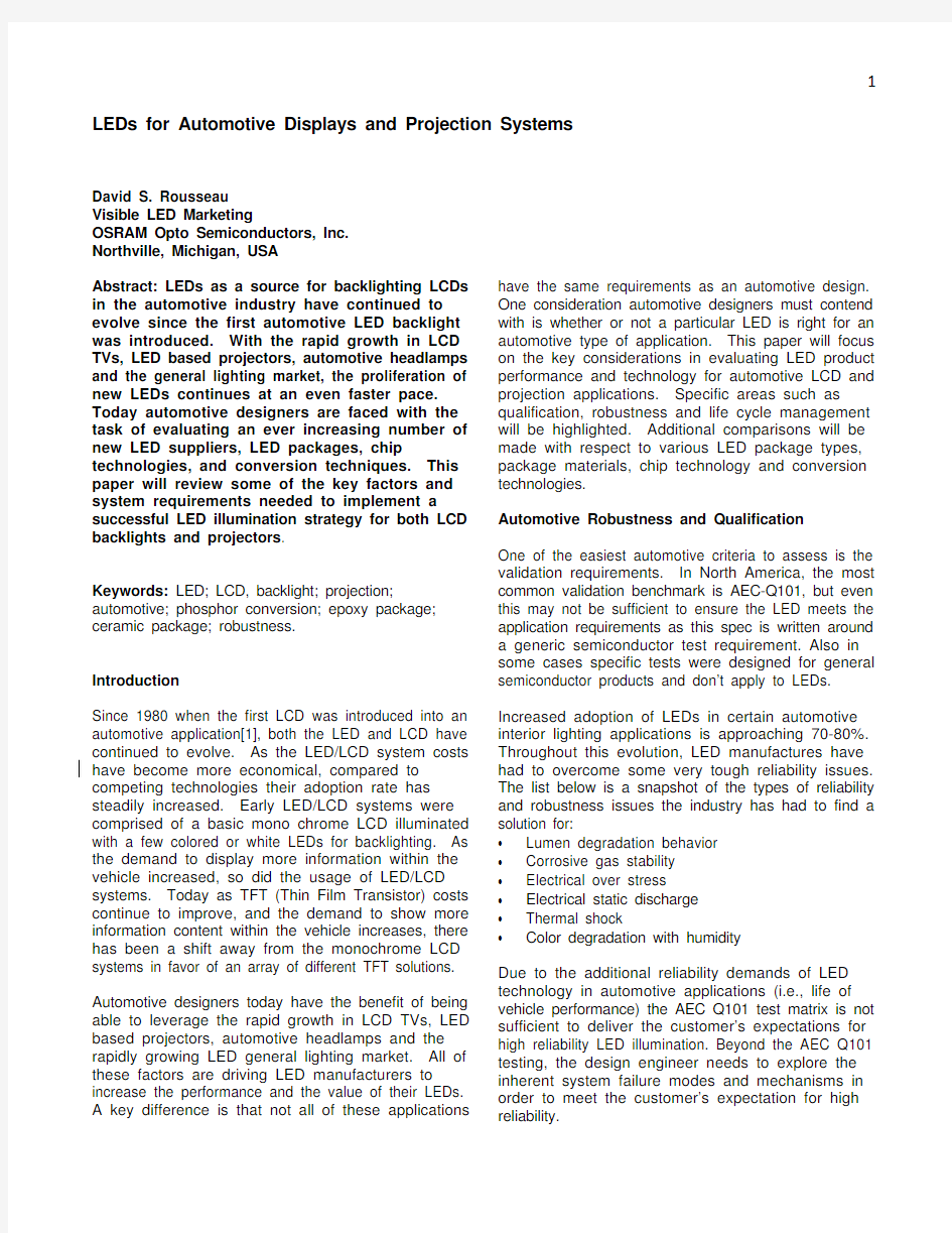
Even if an LED supplier indicates that they meet the AEC-Q101, test selection is subject to interpretation and may vary from supplier to supplier. Figure 1 highlights some of the relevant AEC Q101 tests OSRAM Opto Semiconductors uses. The selection of these tests can vary for the same LED supplier, depending on such factors as whether the bond wire is exposed (i.e., non-casted or non-molded parts).
Figure 1: AEC Q101 Relevant Tests for LEDs
In an effort to rectify these inconsistencies, there is ongoing work at OSRAM Opto Semiconductors with international standards institutes to develop new standards such as the IEC standard (i.e., IEC 68010-3).
Unlike the AEC Q101 specifications, the IEC 68010-3 specification would apply only to LEDs and cover testing for automotive applications, product change management and report formats. SAE will review this specification once it is finalized.
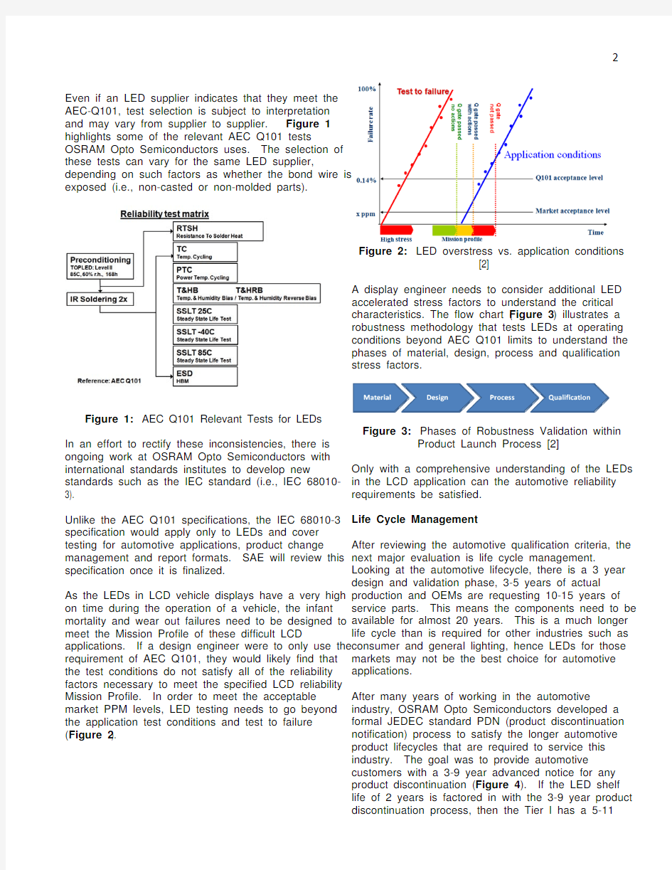
As the LEDs in LCD vehicle displays have a very high on time during the operation of a vehicle, the infant mortality and wear out failures need to be designed to meet the Mission Profile of these difficult LCD applications. If a design engineer were to only use the requirement of AEC Q101, they would likely find that the test conditions do not satisfy all of the reliability factors necessary to meet the specified LCD reliability Mission Profile. In order to meet the acceptable market PPM levels, LED testing needs to go beyond the application test conditions and test to failure (Figure 2
).
Figure 2: LED overstress vs. application conditions
[2]
A display engineer needs to consider additional LED accelerated stress factors to understand the critical characteristics. The flow chart (Figure 3) illustrates a robustness methodology that tests LEDs at operating conditions beyond AEC Q101 limits to understand the phases of material, design, process and qualification stress factors.
Figure 3: Phases of Robustness Validation within
Product Launch Process [2]
Only with a comprehensive understanding of the LEDs in the LCD application can the automotive reliability requirements be satisfied.
Life Cycle Management
After reviewing the automotive qualification criteria, the next major evaluation is life cycle management. Looking at the automotive lifecycle, there is a 3 year design and validation phase, 3-5 years of actual production and OEMs are requesting 10-15 years of service parts. This means the components need to be available for almost 20 years. This is a much longer life cycle than is required for other industries such as consumer and general lighting, hence LEDs for those markets may not be the best choice for automotive applications.
After many years of working in the automotive industry, OSRAM Opto Semiconductors developed a formal JEDEC standard PDN (product discontinuation notification) process to satisfy the longer automotive product lifecycles that are required to service this industry. The goal was to provide automotive customers with a 3-9 year advanced notice for any product discontinuation (Figure 4). If the LED shelf life of 2 years is factored in with the 3-9 year product discontinuation process, then the Tier I has a 5-11
3
year window before a change has to be implemented. This process does not guarantee that every product will meet the 20 year criteria, but it does provide a higher level of assurance that if the 20 year life cycle is not achieved, designers have sufficient time to implement alternate black box solutions. At the root of the life cycle dilemma is an ongoing battle to balance the need for a long life cycle with the need to maintain competitive prices. This official process provides a balance between these conflicting needs. With a 5-11 year buffer, the Tier I suppliers have the time to integrate changes at a more convenient time, such as a model year change over when components systems may have to be revalidated.
Figure 4: Discontinuation Notification Process
LED Packaging
There are many engineering and design tradeoffs
associated with the selection of LED packaging
material that may not be immediately obvious to the
LCD design engineer. For example, lumen depreciation and the degradation phases of ceramic and pre-mold LEDs are very different when a LED is operated in a continuous steady state life test
condition.
Figure 5: Predictive Life Models for White LEDs [3]
Pre-molded LEDs utilize a plastic package which provides higher reliability but may experience degradation due plastic aging or darkening in the early hours of operation, as seen in Figure 5. Figure 5 illustrates the 4 phases of degradation in a pre-molded LED. The phases include: ? Initial chip aging
? Package aging (reflector darkening) ? Stable phase
? Long –term chip degradation
Ceramic packages have a different degradation model due to the optical design of the package and the ceramic material’s resistance to aging mechanisms. These phases are: ? Initial chip aging ? Stable phase
? Long term chip degradation
Another packaging consideration is how the package will handle thermal shock. The package material selection needs to balance the coefficient thermal expansion (CTE) of all of the integral components
within the system (i.e., solder, PCB, ceramic, plastics,
glues, etc.) to deliver the desired system reliability.
Designing for life of vehicle applications with the
extreme thermal shock requirements of -40C to 85C
using ROHS compliant solder can be a challenge at
the systems level reliability. Shown in Figure 6 is the
effect of colder joint cracking after multiple thermal
shocks. The CTE influence was demonstrated in a
comparison study of ceramic vs. molded packages
with interesting tradeoffs in the systems design.
Figure 6: Image of a Ceramic LED after 1000 Thermal
Shock Cycles [4]
Accelerated robustness testing of a ceramic package, and lead-frame based package of equivalent size and performance were tested at the extreme thermal cycle of -40 to 125C. After the parts were tested, the sheer force was measured on the parts and failure rate noted. The data (Figure 7) revealed that both parts performed very well, however, the lead-frame based part had superior resistance to shock at 1000 cycles.
Figure 7: Thermal cycle results[4]
These are just a few examples of packaging tradeoffs when selecting an LED for a high reliability LCD application.
Phosphor Conversion for LCDs
Phosphor materials have a unique role in LEDs for LCD backlighting. A full color TFT display requires a full color gamut of red, green and blue in the spectrum.
This color gamut is accomplished with a two part phosphor system to realize color quality and to produce a high quality display. Typical white LEDs designed for BLU use multi-phosphors to reach this color gamut, but have the following drawbacks:
?Efficiency vs. gamut trade off
?Intensity and operating temperature. and humidity ?Color stability and temperature and humidity Additionally, selecting the right pump wavelength is critical in LCD applications. The interaction of the blue wavelength of the LED and the blue color filters in a TFT display can interact in such a way as to shift the color of the display. For optimal color performance it is necessary to make certain the chip wavelength is matched properly to the characteristics of the color filter. Figure 8 shows how two different chip and phosphor combinations can achieve the same Cx and Cy color coordinates. Even though these different combinations yield the same Cx and Cy color point, the final color differs after passing through the blue color filter of the TFT. The blue color filters on the TFT reduce specific wavelengths of light, thus shifting the final color point.
Figure 8: Achieving common white color point with different chip and phosphor combinations.
Phosphor Conversion for Projection
Until the recent commercialization of ceramic layer conversion with green ceramic in pico and pocket projection, thermal quenching of the phosphor has been an issue and had to be addressed by reducing drive current on the LED in demanding systems. Today there is a newly developed portfolio of C2 (ceramic conversion) technology that will enhance the efficiency of classic white LEDs. The graph in Figure 9 represents the color shift characteristic of a white ceramic converter and a classic powder phosphor. Given the temperature stability as shown in this figure, the C2 demonstrates a clear benefit over traditional
powder phosphors.
Figure 9: C2 vs. Conventional phosphor
In the case of projection systems, the LED light source requires a red, blue and green LED. Since the human eye response is most sensitive at 555nm, green light emission contributes about 75% of the total white screen lumens.
Demand for brighter projection systems has driven the
need for brighter green LEDs. An effective way of producing brighter greens is to utilize phosphor conversion. One issue with phosphor converted green
is that it generates a wide spectrum unlike the narrow bandwidth of a saturated green LED. To overcome this, filters are utilized to narrow the bandwidth of the phosphor converted green.
OSRAM Opto Semiconductors recently released a top emitting UX:3 package with a new ceramic conversion “C 2 Technology” in green that doubled the LED output and delivered 30% more lumens on the screen through a DMD optical system. This has been a significant improvement in performance for small pico and pocket projector systems that could be realized in future automotive HUD displays and free form projection applications. A brightness comparison between the standard ThinGaN True Green and the new UX:3 with the green conversion is highlighted in Figure 10
.
Figure 10: New converted green vs. standard
ThinGaN true green brightness [5]
Chip Technology
One of the driving factors in developing new chips is to get to a high lumen per dollar ratio. To accomplish this there are several chip development strategies: increase the die brightness; reduce effect of droop; and reduce the chip cost. Chip technology has evolved from the GaN/InGaN on SiC substrates to Sapphire and ThinFilm technology (see Figure 11). Recently OSRAM introduced UX3 technology which is based on ThinFilm technology, but incorporates some new internal structures to generate a more uniform current density. This in turn improves the surface light
emission uniformity.
Figure 11: Chip technologies
The underlying concept for the UX3 chip is to incorporate internal current spreading pillars that create a more uniform current density. The end result of the improved current density uniformity is more
uniform light distribution on the chips’ surface. In Figure 12, the UX:3 chip is compared with a standard
ThinGaN chip. The results show that the UX:3 chip has better performance at higher currents. Another benefit of the internal pillars is an improved thermal path allowing the chip to run more efficiently.
Figure 12: Comparison of UX:3 chip performance vs.
standard ThinGaN [6]
Another strategy being employed in chip development is the ongoing effort to drive costs out of the LED. In early 2012 OSRAM Opto Semiconductors made a significant step toward this goal by producing gallium nitride LED chips on a silicon substrate instead of the much more expensive sapphire backing [7].
Summary
Today’s automotive designers have a wide range of LED solutions for both LCD displays and projection systems. To aid in the proper LED selection for an optimized display solution, this paper provided insight into the critical aspects of LED selection. As LED technology continues to advance, designers will need to continually review the advantages of new chip, package and phosphor technologies along with new standards such as IEC 68010-3. Ultimately, the automotive design engineer must establish and balance the priorities between system cost, performance, potential warranty costs and service costs for the display backlight.
Acknowledgements
A special thanks for the contributions of Michael Godwin, Winfried Schwedler and Rich Hawkins. References:
[1] https://www.360docs.net/doc/0416742233.html,
[2] M. Ritzer, Reliability and lifetime considerations for light emitting diodes, April 24, 2012
[3] Reliability of OSLON product family, OSRAM Application Notes
[4] J. Reill, SAE Congress 2010
[5] M. Raukas, Brighter colors from full conversion LEDs, Phosphor Global Summit, March 21, 2012
[6] B. Rieder, M. Wittman, New chip technology, July 2009
[7] LEDs on silicon can reduce production costs, January
2012,https://www.360docs.net/doc/0416742233.html,/innovation/en/new
s/2012/e_inno_1215_1.htm
Author contact:
David S. Rousseau
Visible LED Marketing
OSRAM Opto Semiconductors, Inc
Northville, Michigan, USA 48167
david.rousseau@https://www.360docs.net/doc/0416742233.html,