MBD-902-AL中文资料

Low TCR, 1mW
Dual Rejustor? Micro-Resistor
MBD-472-AL
Information furnished by Microbridge Technologies is believed to be accurate and reliable. However, no responsibility is assumed by Microbridge Technologies for its use, nor for any infringements of patents or other rights of third parties that may result from its use. Specifications subject to change without notice. No license is granted by implication or otherwise under any patent or patent rights of Microbridge Technologies. Trademarks and registered trademarks are the property of their respective companies.
The Rejustor is a precision, electrically-adjustable resistor from Microbridge. The Rejustor can be adjusted to a precision of 0.1%, or better. The Rejustor can be re-adjusted many times bi-directionally within the active range using standard hardware and LabVIEW-based Rejust-it calibration software.
Low-power Rejustors are suitable for applications where the total power dissipation (in the pair) does not exceed 1mW.
As a passive device, there is no warm-up period or boot-up time. Each Rejustor is independently adjustable to any value in the 30% adjustment range while still offering excellent TCR. They are non-volatile , maintaining their adjusted value indefinitely. Each Low-TCR Rejustor maintains 0ppm/K TCR across the adjustment range
within ±100ppm/K. Relative TCR between both Rejustors is less than ±50ppm/K.
PARAMETER
SPECIFICATION
Resistance (as-manufactured) 4.7K ? Minimum adjustable resistance 3.3K ?
Adjustment Precision 0.1% or 0.01%1
TCR (per Rejustor)
0±100ppm/K Power dissipation (per Rejustor) 0.5mW
BENEFITS
Precision electrical in-circuit adjustment Externally adjust or calibrate parameters on
circuits or sensors at final assembly Adjustment process isolated from circuit
allows true in-circuit calibration
Single chip solution to calibrate voltages,
currents, offsets, gains, etc.
No mechanical moving parts – suitable for vibration sensitive applications
Improved reliability; dependability; dust and moisture resistance over mechanical parts Dynamic adjustment provides cost and labor
savings
Flexibility reduces rework cost
1
Adjustment precision is limited by temperature control, accuracy of measurement and adjustment equipment and may increase adjustment time
ELECTRICALLY ADJUSTABLE 4.7K ? 1:1
RESISTOR PAIR
Figure 1: Functional Block Diagram
FEATURES
Electrically adjustable 4.7K ? 1:1 dual resistor Passive, non-volatile variable resistor Adjustment range: 30% down from as-manufactured resistance
Bi-directional adjustment within active range Long term stability 0.5%, see Table 5
Flexibility: Potential for multiple adjustments Stable Temperature Coefficient as resistance
is adjusted – TCR: 0±100ppm/K Power Rating up to 1.0mW at 70o C
Suitable for operation from -40 to +125o C,
refer to Table 2
Passive device, requires no power to operate
or maintain adjustment
Easy to adjust with Rejust-it software and
external DAC/ADC hardware Typical adjust times: ~ 1sec 1.
APPLICATIONS
Anywhere precision adjustment is required Gain and offset adjustment
Reference voltage or current adjustment Precision Voltage Regulator adjustment Filter tuning
RF Amplifier biasing Opto-electronics
Frequency Control devices
Mechanical or digital potentiometer
replacement
Suitable for high-frequency applications
R1ADJ
R2
R2ADJ
R2
HGND
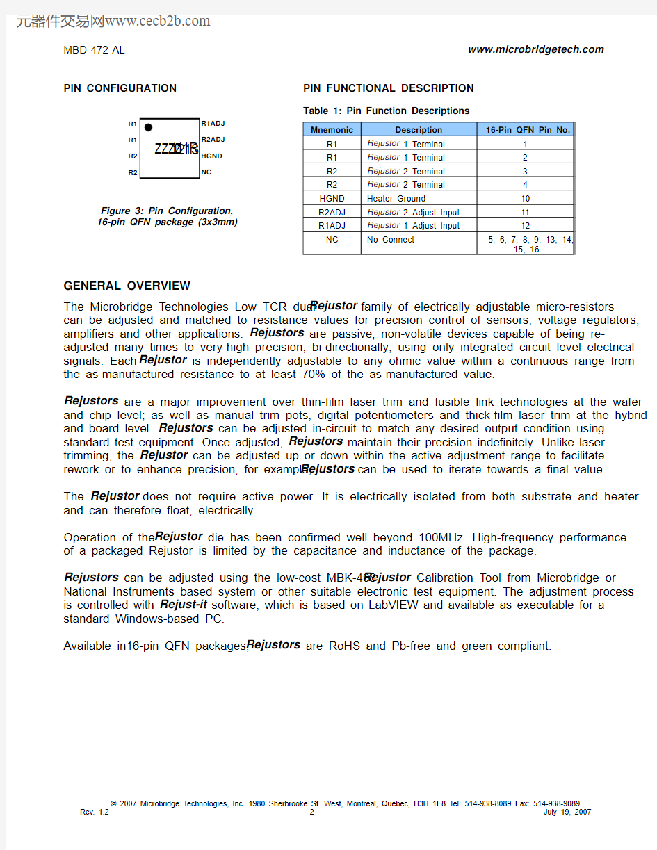
PIN CONFIGURATION
Figure 3: Pin Configuration, 16-pin QFN package (3x3mm)
PIN FUNCTIONAL DESCRIPTION
Table 1: Pin Function Descriptions
Mnemonic
Description
16-Pin QFN Pin No.
R1 Rejustor 1 Terminal 1 R1 Rejustor 1 Terminal 2 R2 Rejustor 2 Terminal 3 R2 Rejustor 2 Terminal 4 HGND Heater Ground 10 R2ADJ Rejustor 2 Adjust Input 11 R1ADJ Rejustor 1 Adjust Input 12
NC
No Connect
5, 6, 7, 8, 9, 13, 14,
15, 16
GENERAL OVERVIEW
The Microbridge Technologies Low TCR dual Rejustor family of electrically adjustable micro-resistors can be adjusted and matched to resistance values for precision control of sensors, voltage regulators, amplifiers and other applications. Rejustors are passive, non-volatile devices capable of being re-adjusted many times to very-high precision, bi-directionally; using only integrated circuit level electrical signals. Each Rejustor is independently adjustable to any ohmic value within a continuous range from the as-manufactured resistance to at least 70% of the as-manufactured value.
Rejustors are a major improvement over thin-film laser trim and fusible link technologies at the wafer and chip level; as well as manual trim pots, digital potentiometers and thick-film laser trim at the hybrid and board level. Rejustors can be adjusted in-circuit to match any desired output condition using standard test equipment. Once adjusted, Rejustors maintain their precision indefinitely. Unlike laser trimming, the Rejustor can be adjusted up or down within the active adjustment range to facilitate rework or to enhance precision, for example, Rejustors can be used to iterate towards a final value.
The Rejustor does not require active power. It is electrically isolated from both substrate and heater and can therefore float, electrically.
Operation of the Rejustor die has been confirmed well beyond 100MHz. High-frequency performance of a packaged Rejustor is limited by the capacitance and inductance of the package.
Rejustors can be adjusted using the low-cost MBK-408 Rejustor Calibration Tool from Microbridge or National Instruments based system or other suitable electronic test equipment. The adjustment process is controlled with Rejust-it software, which is based on LabVIEW and available as executable for a standard Windows-based PC.
Available in16-pin QFN packages, Rejustors are RoHS and Pb-free and green compliant.
NC
NC NC
NC NC
NC
NC NC
Table 2: RATINGS – Rejustor R1 and R2 (4.7K ?) Rejustors 0°C < T A < +70°C; unless otherwise noted.
Item
Conditions Typical Specifications Nominal Resistance R1 4,700? R1 Maximum Power 0.5mW Nominal Resistance R2 4,700? R2 Maximum Power
0.5mW As specified in this datasheet
0°C to +70°C
As specified in Application Note “Rejustor
Operating Guidelines for -40 to +125C Operation”
-40 to +125o
C Operating Temperature
Beyond -40 to +125o
C Contact Microbridge Isolation Voltage (between any pins) Subject to power limits 25V
Total Resistance Tolerance
As-manufactured resistance is ±10% from nominal
Nominal Adjustment range
+0 to -30% from as-manufactured Nominal Pair Matching
Unadjusted
±2%
Table 3: TCR CHARACTERISTICS – Rejustors Characteristics Specification (Worst Case)
Test Method or Conditions
Temperature Coefficient
Unadjusted Adjusted
0±100ppm/K 0±100ppm/K
Change in Temperature Coefficient
± 50ppm/K TCR change in adjusted device relative to unadjusted device, by analysis Temperature Coefficient Matching of pairs
± 10ppm/K
Adjusted to match resistance, by analysis Rejustor Self-heating Coefficient of Resistance +4800 ppm/mW
±20% Per Rejustor , unadjusted
Relative Self-heating Coefficient of Resistance
±100 ppm/mW
When both Rejustors carry the same current
Table 4: PACKAGE ELECTRICAL CHARACTERISTICS
Characteristics Specification (Typical) Test Method or Conditions
QFN Capacitive Loading 0.7pF Per package pin, by analysis at 100MHz QFN Mutual Capacitance
0.1pF
By analysis at 100MHz
2
Where indicated, drift specifications refer to resistance drift in the positive direction. Best performance is achieved at adjustments larger than 10% down from the as-manufactured resistance.
Table 6: MANUFACTURABILITY DATA Characteristics Test Method or Conditions
ESD Discharge JESD22-A114, human body model weakest pin pair, all lead combinations. Class 1A
Solder ability
JESD22-A113, 235o C, slope 6o
C/second
PACKAGING OPTIONS
Table 7: NOMINAL PACKAGE DIMENSIONS
Type Lead Count Body Width Body Length Lead Pitch Lead Width Lead Length Body Thickness JEDEC/ EIAJ QFN
16
3.0mm
3.0mm
0.5mm
0.25mm
0.4mm
0.85mm
MO-220 (VEED)
Figure 4: Package Dimensions
TAPE CARRIER PACKAGING
Figure 5: Tape Carrier Dimensions
All dimensions in millimeters
QFN-16 BOTTOM VIEW
QFN-16 SIDE
Table 8: ORDERING INFORMATION
NOMINAL VALUES AVAILABLE
The following additional Micro Power Dual Rejustors are available with similar performance specifications. Consult the individual datasheet for more information.
Please check with Microbridge Technologies Inc prior to design to ensure you have the
latest revision of the datasheet for this part
3
Where ZZZZ represents the 4-digit date code 4
Smaller sample quantities available on tape
Part Number Order Code
Package Part Marking 3
Delivery Quantity
MBD-472-AL
111R
QFN-16
111R-ZZZZ
Tape and Reel 30004
Part Number Resistance R1 Value (?) Resistance R2 Value (?) Ratio QFN Order Code MBD-472-AL 4700 4700 1:1 111R MBD-472-CL 4700 24,500 1:5 1121 MBD-902-AL 9,000 9,000 1:1 111T MBD-902-CL 9,000 45,000 1:5 1127 MBD-902-XL 9,000 63,000 1:7 111X MBD-153-AL 15,000 15,000 1:1 111Y MBD-153-KL 15,000 45,000 1:3 111U MBD-333-AL
33,000
33,000
1:1
111Z