OCM428中文资料
OCM4M 8, 4M 9 SERIES
Dual-Channel/Package General-purpose Type Optical MOS Relay For AC/DC Load
GENERAL DESCRIPTION
The OCM4M 8 and OCM4M 9 Series are dual-channel, optical MOS relays for AC/DC load. The device is available in the same form factor as single-channel devices, with an 8-pin DIP and SMD-type (gull-wing) package.
FEATURES
?Extremely low voltage control
?High reliability due to non-contact, optical operation ?No chattering or switch bounces ?No mechanical switching noises
?
Small size and easy mounting (6-pin plastic DIP or SMD-type [gull-wing] package)
APPLICATIONS
?Telecommunications equipment ?Measurement equipment ?Home electronics
?Automatic meter reading equipment
?Other applications requiring small size or high performance ?
Other applications requiring non-contact switches
E2P0051-37-X3
This version: Jan. 1998
Previous version: May. 1997
元器件交易网https://www.360docs.net/doc/122646887.html,
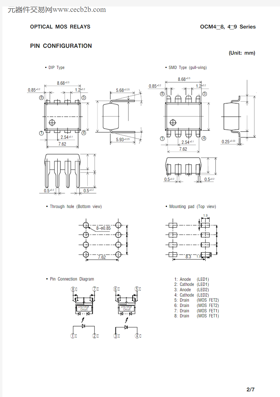
PIN CONFIGURATION
(Unit: mm)
1: Anode 2: Cathode 3: Anode 4: Cathode 5: Drain 6: Drain 7: Drain 8: Drain ? Pin Connection Diagram
(LED1)(LED1)(LED2)(LED2)
(MOS FET2)(MOS FET2)(MOS FET1)(MOS FET1)
? Through hole (Bottom view)? Mounting pad (Top view)
? DIP Type
? SMD Type (gull-wing)
0°+15–0
0°+15–0
1
8
4
5
8.68
±0.5
0.85
±0.2
1.2
±0.2
5.93±0.25
5.68
±0.25
2.54±0.10.5±0.2
0.5±0.27.62
6.4±0.3
7.62±0.15
0.25±0.03
3.65±0.2
4.75m a x .
0.8±0.2
2.8±0.35
18
4
5
8.68±0.5
0.85±0.2
1.2±0.2
2.54±0.17.62
6.4±0.3
0.5±0.20.5±0.2
3.65±0.2
4.0±0.2
0.25±0.03
1.1±0.4
1.1±0.4
9.9±0.6
ABSOLUTE MAXIMUM RATINGS
Product Name
Parameter
Symbol
Condition Unit OCM408OCM408I n p u t C h a r a c t e r i s t i c s
Derating Factor of Continuous Forward Current
I F
Pulse width 100 m s Cycle 10 ms
Pulse width 1 ms 1shot
(Ambient temperature Ta=25°C )
OCM418OCM419OCM428OCM429OCM438OCM439Continuous Forward Current Peak Forward Current Reverse Voltage Power Dissipation Load Voltage Load Current Derating Factor of Load Current Surge Load Current Power Dissipation
Storage Temperature
Operating Temperature Isolation Voltage Total Power Dissipation O u t p u t C h a r a c t e r i s t i c s
D I F
I FM V R P DL V OFF I ON D I ON I SUG P D
P tot
V IO T opr T stg
mA mA/°C
A V mW V mA mA/°C
A mW mW
V(rms)
°C °C
50
Refer to [Derating Factor of Continuous Forward Current] of characteristics data
0.55200100
Refer to [Derating Factor of Load Current] of characteristics data 0.5
3003251500
OCM4284000
OCM429–40 to +85–40 to +100
35075
OCM438OCM439100150
OCM418OCM41960200
OCM408OCM40975
0.3
OCM448
OCM44940050
OCM448
OCM449
ELECTRICAL CHARACTERISTICS
Product Name
Parameter Symbol
Condition Unit OCM408OCM409I n p u t C h a r a c t e r i s t i c s
Reverse Voltage
V F V OFF =50 V f=1 MHz (Ambient temperature Ta=25°C )
OCM418OCM419OCM428OCM429OCM438OCM439Forward Voltage Recovery Input Current On-resistance Off-state Leakage Current Output Terminal Capacitance O u t p u t C h a r a c t e r i s t i c s
I R
I FR R ON
I OFF C OUT Min.m A
mA W m A pF 1.0100.2
1.0
Max.
I F =10 mA V
V R =5 V Max. 1.3Operation Input Current I FA
mA
5I ON =100 mA or Rating Max.V OFF =Rating I ON =100 m A
Min.*1Min.12255.04.0Typ.
1635
7.0
5.0
Max.I F =10 mA I ON =100 mA
*2V OFF =Rating Max.Typ.Input-to-output Capacitance C IO
pF 1.3f=1 MHz
Typ.t ON Turn-on Time Typ.0.3Max.I F =10 mA
I on =100 mA ms 1.0t OFF
Turn-off Time
Typ.0.2Max.
ms
1.0
C o u p l i n g C h a r a c t e r i s t i c s OCM408, 409OCM418, 419OCM428, 429OCM448
OCM4495070
8610155
I off =50 mA
OCM438, 439OCM448, 449
*3*3OCM408, 409, 418, 419
I ON =Rating
Time to flow current is
within one second
*1 : Can correspond to special specification I FA <3.0 mA *2 : Can correspond to special specification I OFF <1.0 nA
*3 : Can correspond to special specification t ON / t OFF <0.5 ms
TYPICAL CHARACTERISTICS
?Derating Factor of Continuous Forward Current
?Derating Factor of Load Current
?Operation Input Current vs.Ambient Temperature
?Recovery Input Current vs.Ambient Temperature
0–40
050100
30
10
20
40
50
Temperature Ta (°C)C o n t i n u o u s F o r w a r d C u r r e n t I F (m A
)
60
50
100
Temperature Ta (°C )
C o n t i n u o u s L o a d C u r r e n t I O N (m A )
–40
0050100
510
Temperature Ta (°C )O p e r a t i o n I n p u t C u r r e n t I F A (m A )
–40
0050100
5
10
Temperature Ta (°C )
R e c o v e r y I n p u t C u r r e n t I F R (m A )
–40
?On-resistance vs. Ambient Temperature 1
?On-resistance vs. Ambient Temperature 2
005010025
1015
20Temperature Ta (°C )O n -r e s i s t
a n c e R O N (W )
–40
050100
75
25
100
Temperature Ta (°C )
O n -r e s i s t a n c e R O N (W )
–40
125
?Continuous Forward Current vs.Turn-on/Turn-off Time
?Output Terminal Capacitance vs.Applied Voltage
?Continuous Forward Current vs.On-resistance 1
?Continuous Forward Current vs.On-resistance 2
?Turn-on/Turn-off Time vs.Ambient Temperature
?Off-state Leakage Current vs.Ambient Temperature
1
10
0.2
T u r n -o n / T u r n -o f f T i m e (m s )
Input Current I F (mA)
10100
Applied Voltage (V)
O u t p u t T e r m i n a l C a p a c i t a n c e
C o u t (p F )
00
10
5
10
20
Input Current I F (mA)O n -r e s i s t a n c e R
O N (W )
00
40
100
60
10
20
80
20
Input Current I F (mA)
O n -r e s i s t a n c e R O N (W )
50
100
Temperature Ta (?C )T u r n -o n / T u r n -o f f T i m e (m s )
–40
10 050100
10
10
–8
10
Temperature Ta (°C )
O f f -s t a t e L e a k a g e C u r r e n t I O F F (A )
–40
?Load Current vs. Voltage
?Example Circuit for Measuring Turn-on/Turn-off Time
I F
V OUT
V OUT
–2.5
250
–250
0 2.5
Voltage (V )
L o a d C u r r e n t I O N (m A )