SDR1006TTEB100M中文资料
Fixed High-Frequency Inductors
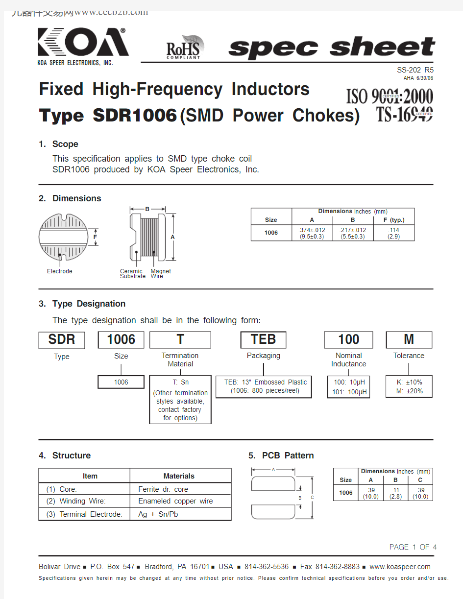
Type SDR1006 (SMD Power Chokes)
1.Scope
This specification applies to SMD type choke coil SDR1006 produced by KOA Speer Electronics, Inc.
Item
Materials
(1) Core:Ferrite dr. core (2) Winding Wire:Enameled copper wire (3) Terminal Electrode:
Ag + Sn/Pb
4.Structure
SS-202 R5
AHA 6/30/06
Bolivar Drive I P.O. Box 547 I Bradford, PA 16701 I USA I 814-362-5536 I Fax 814-362-8883 I https://www.360docs.net/doc/1316753981.html,
3.Type Designation
The type designation shall be in the following form:
Size
Tolerance
Nominal Inductance
1006
K: ±10%M: ±20%
100: 10μH 101: 100μH
1006
M
100
Packaging
TEB: 13" Embossed Plastic (1006: 800 pieces/reel)
TEB
Termination Material
T: Sn (Other termination styles available,contact factory for options)
T
SDR
Type
5.PCB Pattern
A B C Dimensions inches (mm).39(10.0)
.11(2.8)
.39(10.0)
1006
Size
CERTIFIED
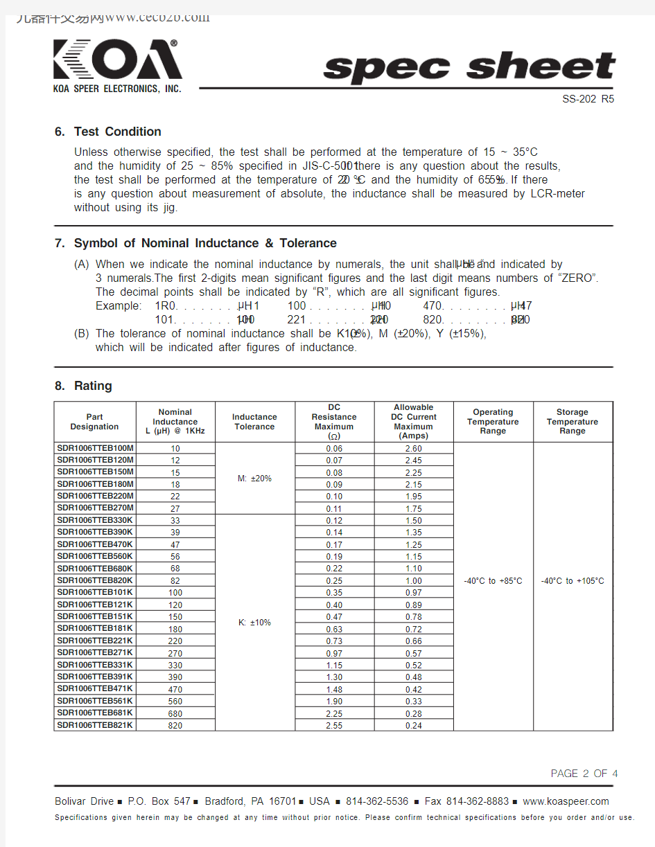
8.Rating
6.Test Condition
Unless otherwise specified, the test shall be performed at the temperature of 15 ~ 35°C
and the humidity of 25 ~ 85% specified in JIS-C-5001.If there is any question about the results, the test shall be performed at the temperature of 20 ±2 °C and the humidity of 65 ±5%.If there is any question about measurement of absolute, the inductance shall be measured by LCR-meter without using its jig.
7.Symbol of Nominal Inductance & Tolerance
(A)When we indicate the nominal inductance by numerals, the unit shall be “μH”and indicated by
3 numerals.The first 2-digits mean significant figures and the last digit means numbers of “ZERO”.The decimal points shall be indicated by “R”, which are all significant figures.Example:1R0. . . . . . . . . 1μH 100. . . . . . . . 10μH 470. . . . . . . . . 47μH
101. . . . . . . 100μH 221. . . . . . . 220μH 820. . . . . . . . 820μH
(B)The tolerance of nominal inductance shall be K (±10%), M (±20%), Y (±15%),
which will be indicated after figures of inductance.
SS-202 R5
Part Designation Nominal Inductance L (μH) @ 1KHz
DC Resistance Maximum
(?)Allowable DC Current Maximum (Amps)Operating Temperature
Range
Storage Temperature
Range
Inductance Tolerance
1012151822273339475668821001201500.060.070.080.090.100.110.120.140.170.190.220.250.350.400.47 2.602.45-40°C to +85°C -40°C to +105°C
2.252.151.951.751.501.351.251.151.101.000.970.890.78SDR1006TTEB100M SDR1006TTEB120M SDR1006TTEB150M SDR1006TTEB180M SDR1006TTEB220M SDR1006TTEB270M SDR1006TTEB330K SDR1006TTEB390K SDR1006TTEB470K SDR1006TTEB560K SDR1006TTEB680K SDR1006TTEB820K SDR1006TTEB101K SDR1006TTEB121K SDR1006TTEB151K M: ±20%
K: ±10%
1802200.630.730.720.66SDR1006TTEB181K SDR1006TTEB221K 270330390470560680820
0.971.151.301.481.902.252.55
0.570.520.480.420.330.280.24
SDR1006TTEB271K SDR1006TTEB331K SDR1006TTEB391K SDR1006TTEB471K SDR1006TTEB561K SDR1006TTEB681K SDR1006TTEB821K
10.Environmental Tests
Item Performance Test Method (JIS C5321)
Resistance to Change of To leave in a bath at -40 ±2 °C for 1,000 hours.
Cold Inductance: ±10%
Temperature Change of To keep at -25°C ~ 85°C for 30 minutes in 5 cycles and leave for
Cycling Inductance: ±10%10 ~ 15 minutes in normal temperature at the time of transition between
low temperatures and high temperatures
Resistance to Change of To leave in a bath at 85 ±2 °C for 2 hours.
Heat Inductance: ±10%(Resistance to heat of Ferrite Core: 120°C)
T. C. R Change of20°C shall be standard and change of inductance shall be measured
Inductance: ±5%at -25°C ~ 85°C.
Resistance to Change of Temperature: 60 ±2 °C
Damp Inductance: ±10%Humidity: 90 ~ 95%
(Steady State)Test hours: 1,000 hours
Endurance Change of Temperature: 40 ±2 °C
(Under Damp Inductance: ±10%Humidity: 90 ~ 95%
and Load)To supply allowable current for 1,000 hours continually
Endurance Change of Temperature: 85 ±2 °C
(Under high Inductance: ±10%To supply allowable current for 1,000 hours
Temperature)
SDR1006 Packaging Carrier Tape Reels
Type A B C G N T 1006
12.98.944.511 ±.02 1.02 1.97 1.24(330)
(24 ±1)
(13 ±0.5)
(26)
(50 Min.)
(31.5)
Materials:
Paper Plastics
Dimensions in inches (mm)
SS-202 R5