Towards UML-based Analysis and Design of Multi-Agent Systems
Towards UML-based Analysis and Design of Multi-Agent Systems
Stephan Flake,Christian Geiger,Jochen M.K¨u ster
C–LAB,Fuerstenallee11,33102Paderborn,Germany
email:?ake,chris,jkuester@c-lab.de
Abstract
The visual modeling facilities of the UML do not provide
suf?cient means to support the design of multi-agent sys-
tems.In this paper,we are investigating the development
phases of requirements analysis,design,and code gener-
ation for multi agent systems.In the requirements anal-
ysis phase,we are using extended use case diagrams to
identify agents and their relationship to the environment.
In the design phase,we are using stereotyped class and
object diagrams to model different agent types and their
related goals and strategies.While these diagrams de?ne
the static agent system architecture,dynamic agent be-
havior is modeled in statecharts with respect to the BDI1
agent approach.Concerning code generation,we show
how the used diagrams can be taken to generate code for
CASA,our executable agent speci?cation language that
is integrated into an existing multi-agent framework.
1Introduction
Designing agent-based systems is a complex and de-
manding task.As agents are in itself software systems,
they should be treated as such,and well-known software-
engineering principles should be taken into consideration
when designing agent-based systems.Currently,several
different agent architectures exist,and one of the best
known is probably the BDI-architecture.While there has
been a lot of work concerning the development of speci?c
agent architectures,only little work has been directed to
solve software engineering problems which result from
the advent of agents.Although agent-based systems are
software systems,they can be distinguished from an or-
dinary software system.Key characteristics of agents are
autonomy,pro-activity,reactivity and temporal continu-
ity[8].Agent-based systems literature distinguishes mi-
cro and macro views.The micro view considers the local
behavior of an individual agent(e.g.strategies,knowl-
edge,behavior),whereas its environment and interaction
standardization of UML by the OMG.Nowadays,the UML is widely used in industry and academia.
The UML consists of several different forms of https://www.360docs.net/doc/3c6546903.html,e Case Diagrams are used to capture the re-quirements and interactions with the user of the system to be built.Static structure diagrams such as class diagrams allow the modeling of static structure aspects of the sys-tem.Statechart diagrams and Activity diagrams are ap-plied for modeling the dynamics of the software system. Finally,implementation diagrams support the modeling of distributed components of the system.
Software construction is tremendously facilitated by CASE-tools.These tools allow the software engineer to construct UML models of the software system to be built during analysis and design.They also support the soft-ware engineer by code generation and consistency checks of models.
As agent-based systems are software systems,they should be modeled with UML or an extension of the UML such as Agent UML[1].Recently,several ap-proaches have been made to establish a modeling lan-guage for agents.It is our opinion that if agents are to be-come successful there has to be code generation and other techniques supporting the software engineer in the devel-opment of agent-based systems.Therefore,we show how to model agents with UML and how to map these UML models on an implementation.
3Related Work
Agent-oriented software engineering goes back to the Gaia methodology[18].Gaia proposes a role-oriented approach for the analysis and design of agent-based sys-tems.After identi?cation of key roles in the system a de-tailed role model is constructed.Roles are then mapped to an agent class model.Whereas Gaia is not based on the UML but provides an own notation,the Multiagent Sys-tems Engineering methodology(MaSE)by Wood et al.
[17]uses goal models,agent class models and commu-nication class diagrams in an UML-like notation.Other than the approach described in this paper,MaSE does not include any means of modeling rules or plans of agents. Focusing on characteristics such as autonomy,re-activity,and pro-activity of agents,role models and graph transformation were introduced in order to model agent roles and operations performed by the agents [4,3].Global graph transformations are used during the requirements phase,while local graph transforma-tions can be used to model autonomy aspects of agents. Whereas graph transformations are well-suited for mod-eling agents on a conceptual level,it remains unclear how to transform such systems to an agent-based implementa-tion.
Modifying the UML for agent-based software engi-neering is not a new idea.Our extensions of use case diagrams for agents have been inspired by the UER tech-nique[12].Other extensions include the adaptation of sequence diagrams for representing agent interaction pro-tocols[14].
However,in this paper,we do not describe the adap-tation of UML to fully support modeling of agent-based systems.Moreover,we try to show how the internals of agents such as goals and strategies to achieve those goals can be captured using UML and how to map these di-agrams on the existing agent system CASA.Before de-scribing this mapping we brie?y sketch CASA,our speci-?cation language for ef?ciently designing complex MAS. 4CASA
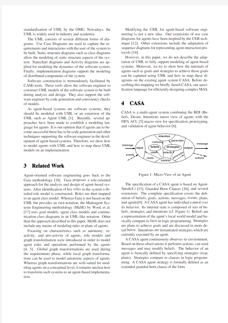
CASA is a multi-agent system combining the BDI(Be-liefs,Desire,Intention)micro view of agents with the FIPA ACL[5]macro view for speci?cation,prototyping, and validation of agent behavior[6].
generates
selects
message
message
reads
control
events
input
uses
actions
output
intention
beliefs strategies
controls
g e
n e
r a t
e s
Figure1:Micro View of an Agent
The speci?cation of a CASA agent is based on Agent-Speak(L)[15],Guarded Horn Clauses[16],and several extensions.The complete speci?cation covers the de?-nition of beliefs,goals,actions,messages,events,plans, and agents[9].A CASA agent has individual control over its behavior.Its internal state is composed of sets of be-liefs,strategies,and intentions(cf.Figure1).Beliefs are a representation of the agent’s local world model and ba-sically compare to facts in logic programming.Strategies are plans to achieve goals and are discussed in more de-tail below.Intentions are instantiated strategies which are currently executed by an agent.
A CASA agent continuously observes its environment. Based on these observations it performs actions,can send messages and may modify beliefs.The behavior of an agent is basically de?ned by specifying strategies(resp. plans).Strategies compare to clauses in logic program-ming.A CASA agent strategy is formally de?ned as an extended guarded horn clause of the form
where is the head,are guards,are body predi-cates,and de?nes a priority.
The head of a CASA strategy describes the event the agent must perceive in order to instantiate the plan.The guard elements de?ne test conditions that the arguments of the perceived event must satisfy.Only if all test con-ditions are valid a strategy is considered as being appli-cable.Additionally,a priority allows to choose between different applicable strategies.
CASA agents distinguish between different types of strategies.If all guards are just testing the validity of lo-cal beliefs,the strategy is considered as being reactive.If the strategy’s guards include goals,the strategy is delib-erative,because the evaluation of such guards requires a speculative computation which evaluates other strategies in order to reduce the goal(multi level plans).If com-munication between agents is required in the strategy’s guards,the strategy is communicative.If multiple strate-gies can be applied,reactive strategies take precedence over deliberative strategies,which in turn take prece-dence over communicative strategies to optimize perfor-mance.
During execution,an agent can suspend currently exe-cuted strategies and resume suspended ones by using spe-cial operations for suspending/resuming.
messages actions
Figure2:CASA Agent Execution Cycle
The operational semantics of a CASA agent can be best described by means of an abstract interpreter as il-lustrated in Figure2.The interpreter manages the execu-tion of all agent activities in an interpretation loop.The operation of the agent interpreter is controlled by three functions that control event selection,plan selection,and intention selection.
The interpretation starts with the selection of a per-ceived event.Then a set of relevant plans for process-ing the selected event is identi?ed.The preconditions of all relevant plans are checked against the beliefs and plans stored in the agent to extract the set of applicable plans,i.e.,plans whose preconditions are satis?ed.One applicable plan from that set is selected as the pursued strategy.This plan is then instantiated on the agent’s in-tention multistack.The multistack concept allows each agent to investigate several plans in parallel and to instan-tiate new(sub)intentions.Finally,the interpreter selects an intention from the multistack and executes it starting from the top element.Execution can result in direct ac-tions,sending out messages,or generation of new events for(sub)intentions.Thereafter,the interpreter advances to process the next event.
A CASA agent is de?ned using the CASA speci?-cation language.In the context of modeling agent be-havior the agent’s beliefs and strategies are most rele-vant.Therefore,we focus on the speci?cation of facts and plans.Facts are structured as a list of corresponding identi?ers and values:
FACTS:
FACT;
...
FACT;
Plans consist of a name identifying the plan,a descrip-tion indicating the functionality of the agent,a goal that the plan is designed to achieve,and the functionality def-inition corresponding to the guarded horn clause formal-ism:
PLAN:
{
NAME:
DESCRIPTION:
GOAL:ACHIEVE
TYPE: |DELIBERATIVE |COMMUNICATIVE>; PRECONDITION: BODY: FAILURE: PRIORITY: } In addition to the de?nition of the body,a failure sec-tion can be de?ned that is elaborated when the evaluation of the body fails.Control structures like if-then-else,wait conditions,or parallel execution blocks can be applied in preconditions,the body,and the failure section.CASA agents are integrated into the MECCA agent management framework[2]which implements the FIPA ACL(Agent Communication Language)standard[5].A CASA agent reads and writes messages through a speci?c communi-cation adaptor from and to the internal message trans-port channel of the MECCA system.This allows CASA agents to communicate with any FIPA compliant agent via the MECCA framework as it is shown in Figure3. For the illustration of our UML-based engineering ap-proach of CASA agents we used a case study of an ap- Figure3:CASA and MECCA Architecture plication taken from a virtual world simulation,which is described in the next section. 5Case Study:Dog versus Cat In our case study we consider two autonomous agents in a virtual world:a chasing game between dog and cat. In this application,two actors are inserted into a con-?ned area,where the goals of one character(the dog) are to get enough food,to avoid collisions while mov-ing,and to chase the other character(the cat).The cat has the goals to get enough food,to avoid collisions,and to escape from the dog if it is being chased.Accord-ingly,both agents have strong tendency to reach their goals,however,complex behavior might enable them to improve their chances of success.As an example,the cat might use some hiding technique to evade the dog as long as possible.In[11],hierarchical fuzzy logic controllers (FLCs)were used to model the animal’s movement.Be-havior patterns like”If the dog is right behind the cat at high speed,the cat makes a sharp left turn”can be eas-ily modeled using fuzzy logic.Simple fuzzy controllers for processing position,angle of sight,or velocity were hierarchically organized.The results presented in[10] show that FLCs are a suitable means for the simulation of complex behavior of these agents.To allow autonomous agents to process non sharp values in their chasing game, our approach makes use of a custom Fuzzy Logic Con-troller library we developed recently[7].Using this ex-tension,fuzzy controllers can be easily used in our CASA system.The fuzzy rule base is modeled as a special fact and controller operations like fuzzify,infer and defuzzi?-cate are modeled as actions.This approach requires the extension of CASA by new types for events,facts,and ac-tions,see[7,10].Due to different possible strategies for reaching the goals,dependencies and con?icts between goals and varying importance weights for goals during the simulation the design of an agent’s behavior is not trivial.Figure4shows the application using CASA and a 3D graphics library(Java3D),as it was presented in [10]. Figure4:Dog vs.Cat Application 6UML-based Agent Models and their Mapping to CASA In this section,we give an overview of how to model agent-based systems with the UML and how to map UML models to CASA,focusing on the micro view of agents. At some points,we will extend the UML and adapt it to support modeling of agent-based systems by introducing new stereotypes. Following the UML-based design approach,use case diagrams are applied to capture the interactions of the system with the user.In order to take into account the notion of agency,we distinguish between ordinary users modeled as actors,agents that are modeled as actors with square heads,and elements of the environment that are modeled as clouds.Furthermore,apart from ordinary use cases,goal cases and reaction cases are introduced ex-pressed by stereotyped use cases.A goal case serves as a means of capturing high level goals of an agent.Re-action cases are used to model how the environment di-rectly in?uences agents.An arc between an actor and a reactive use case expresses that the actor is the source of events triggering this use case.Figure5illustrates our case study:the dog triggers the reactive use case DogDe-tected in the cat agent.In the environment,the tree trig-gers the TreeDetected use case in the cat. From a use case diagram,an agent class diagram is de-veloped.In the BDI agent approach,an agent has strate-gies,goals,and facts.Also,it can react to observed events in the environment and provides a communication inter-face. In our approach,an agent is modeled as an active ob-ject,implying that it has its own thread of control(see Figure6).In order to capture agent related aspects of Figure 5:Dog vs.Cat -Use Case Diagram the system we have to make the following extensions:Facts are modeled as attributes of the agent.In our view,an agent is composed of strategies and goals with each strategy dedicated to ful?ll a goal.Events from the envi-ronment perceived by the agent are modeled as ordinary operations in a method interface of the agent.Note the re-lationship of reactive use cases and the operations in the method interface of an agent.A newly introduced com-partment named FIPA interface allows the modeling of the FIPA messages the agent can respond to. Figure 6:Agent Class Diagram for the Cat Goals and strategies both have a priority attribute by default.A strategy is a rule and therefore consists of pre-conditions and actions which are both modeled as oper-ations.Two named compartments are introduced for this purpose.Preconditions must return a boolean value.Following the object-oriented paradigm,we also intro-duce an instance diagrams for concrete objects of the sys-tem in the terms of UML object diagrams.We will use instance diagrams to capture the initial con?guration of the system.Figure 7illustrates main parts of the instance diagram for the cat in our case study.The attributes of the cat,its strategies and its initial goals are set to spe-ci?c initial values. Figure 7:Agent Instance Diagram for the Cat In order to capture the dynamics of agents,we again use diagrams of the UML.The dynamics are de?ned by the way how an agent reacts to messages from the en-vironment and other agents,how it communicates with other agents and,on a micro level,which actions it takes in order to achieve its goals. Strategies can be considered as plans in order to achieve a certain goal.So far,a strategy consists only of preconditions and actions,both in form of operations.For each strategy,a statechart is provided which models one plan of an agent. Figure 8:High Level Plan to Avoid the Dog We distinguish between high-level and detailed plans.The high-level plan illustrated in Figure 8shows the plan of the cat for avoiding the dog.Initially,the plan is inac-tive and stored in the CASA plan library.On perception of a dogDetected event,it is activated.After analyzing the current situation the cat tries to escape and then the plan becomes inactive again.This high-level plan can be viewed as a general template for agent plans.High-level plans allow the modeling of plans in a visual and easy-to-understand way. Re?nement of high-level plans leads to detailed level plans.In order to be able to map UML models on CASA, we have to restrict plans to be conform to the format of preconditions followed by actions.We therefore only al-low statecharts which consist of two compound states,one modeling preconditions and another one modeling the body of the formula.In the precondition compound state,only operations of the precondition compartment of the strategy can be called. Figure 9:Detailed Plan to Avoid the Dog For the Dog-Cat example,the plan to avoid the dog is presented in Figure 9.In the precondition state,the cat receives its own position and the current position of the dog.If both conditions are known,the cat proceeds to the plan body,where fuzzy rules are applied to calculate the cat’s new direction and velocity. In addition to the presented use of UML-based dia-grams,we apply statecharts for further agent micro view aspects like processing of events perceived by the agent,selection of a strategy if more than one strategy is applicable for a goal, modeling agent behavior with respect to FIPA stan-dardized communication. On the macro level of inter-agent behavior,sequence diagrams can be used to model interaction protocols,as it is presented in [14]. In the following,we brie?y discuss how to extract in-formation from the previously presented diagrams to gen-erate CASA code.First,we generate an agent’s initial set of beliefs and their values.Recalling Figures 6and 7,we get the following code for the agent Cat (only in part due to space limitations): FACTS: FACT position 2290.0;//Tuple ... FACT obstacleDetected false; //Boolean Moreover,for each method of the method interface a reactive plan without preconditions is generated.At run-time,appropriate goal events perceived by the agent ?re these plans.For instance,a reactive plan “TreeDetection”without any precondition is generated from the diagram in Figure 6.In addition,more complex plans can be gen-erated from the strategies which are explicitly modeled in class diagrams like in Figure 6.Together with the corre-sponding instance and statechart diagrams (cf.Figures 6,8and 9),the following CASA code can be generated: PLAN:{NAME:"CatAvoidsDog"; GOAL:ACHIEVE "AvoidDog";TYPE: COMMUNICATIVE;PRECONDITION:PARALLEL {ACHIEVE getDogPosition : 1.0;}{ACHIEVE getOwnPosition : 1.0;}BODY: FUZZIFY;INFER; DEFUZZIFY; EXECUTE setDirectionAndVelocity;FAILURE://empty PRIORITY: 1.0; } Note that plan priorities are taken from instance dia-grams,while plan types,pre-conditions,and body are taken from statecharts.The code presented here is not complete,e.g.,values and local variables for fuzzy op-erations are still missing.They may either be extracted from more detailed statecharts or must be completed in the resulting CASA code. An agent’s initial goals are extracted from instance di-agrams.For example,the cat in our case study could have two initial goals,which are speci?ed in a separate GOALS-section in CASA: GOALS:{ ACHIEVE AvoidDog : 1.0;ACHIEVE DontStarve : 1.0;} Code generation of a CASA agent speci?cation is com-pleted by de?ning three selection functions which are necessary in the agent interpreter for selecting events,plans,and goals.This information is again taken from instance diagrams and additional statechart diagrams. 7Conclusion Based on the observation that the UML does currently not provide suf?cient means for the design of MAS,we have developed dedicated diagram extensions with re-spect to the following three development phases:In the requirements analysis phase,we identify agents and their relationship to the environment in use case diagrams by new actor symbols and use case stereotypes.In the de-sign phase,we have extended class and object diagrams to model agent types and their related goals and strate-gies.For modeling dynamic behavior,a restricted for-mat of statecharts is used,as we are focusing on the BDI-architecture for the micro view of agents.Finally, we have shown how executable CASA agent speci?ca-tion code can be generated from the presented UML dia-grams. Currently,we are investigating whether code gener-ation can also be applied for other programming lan-guages,e.g.,object-oriented languages like Java,thus making our approach more?exible. Acknowledgments We gratefully acknowledge Markus Latzel’s work in im-plementing the Dog-Cat case study described in this pa-per.Additionally,Guido Grottendieck’s3D Animation Creator provided us with a powerful tool to develop the 3D actors. References [1] B.Bauer,J.P.Mueller,and J.Odell.Agent UML:A For- malism for Specifying Multiagent Software Systems.In Proc.ICSE Workshop on Agent-oriented Software Engi-neering,Limerick,Ireland,June2000. [2] B.Bauer and D.Steiner.MECCA-System Reference Manual.Internal Documentation,Siemens AG,Munich, Germany,1998. [3]R.Depke,R.Heckel,and J.M.K¨u ster.Integrating Visual Modeling of Agent-Based and Object-Oriented Systems. In Proc.of the4th Int.Conference on Autonomous Agents, Agents’2000,Barcelona,Spain,June2000. [4]R.Depke,R.Heckel,and J.M.K¨u ster.Requirement Spec- i?cation and Design of Agent-Based Systems with Graph Transformation,Roles and UML.In Proc.ICSE Work-shop on Agent-oriented Software Engineering,Limerick, Ireland,June2000. [5]FIPA.FIPA2000Speci?cation-FIPA ACL Message Structure Speci?cation.Foundation for Intelligent Physi-cal Agents,Geneva,Switzerland,2000.Available under http://www.?https://www.360docs.net/doc/3c6546903.html,/repository/aclspecs.html. [6]S.Flake and C.Geiger.Agents with Complex Plans:De- sign and Implementation of CASA.In From Agent Theory to Agent Implementation II,Proc.of the15th European Meeting on Cybernetics and Systems Research,Vienna, Austria,April2000. [7]S.Flake, C.Geiger,G.Lehrenfeld,W.Mueller,and V.Paelke.Agent-Based Modeling for Holonic Manufac-turing Systems with Fuzzy Control.In18th International Conference of the North American Fuzzy Information Pro-cessing Society,NAFIPS’99,New York,USA,June1999. [8]S.Franklin and A.Graesser.Is it an Agent,or just a Pro- gram:A Taxonomy for Autonomous Agents.In Proc.of the Third International Workshop on Agent Theories,Ar-chitectures,and Languages(ATAL),pages193–206,Bu-dapest,Hungary,1996. [9] C.Geiger.Rapid Prototyping of Interactive3D Anima- tions.PhD thesis,University of Paderborn,September 1998.(in German). [10] C.Geiger and https://www.360docs.net/doc/3c6546903.html,tzel.Prototyping of Complex Plan Based Behavior for3D Actors.In Proc.of the4th Int.Conference on Autonomous Agents,Agents’2000, Barcelona,Spain,June2000. [11]S.Ginsburg,R.Wimmer,and H.P.Geering.Fuzzy Con- trol:Clever Dog vs.Smart Cat.Technical Report28, ETH Zuerich,Zuerich,Switzerland,1995. [12] C.A.Iglesias and M.Garijo.UER Technique:Conceptu- alisation for Agent Oriented Development.In M.P.Singh, A.Rao,and M.J.Wooldridge,editors,Proceedings of the 4th International Workshop on Agent Theories,Architec-tures,and Languages(ATAL-97,volume1365of LNAI, pages313–328,Berlin,July24–261999.Springer. [13]Object Management Group.OMG Uni?ed Modeling Lan- guage Speci?cation Version1.3,March2000.Avail-able under https://www.360docs.net/doc/3c6546903.html,/technology/documents/-formal/uni?ed language.htm. [14]J.Odell,H.Van Dyke,and B.Bauer.Representing Agent Interaction Protocols in UML.In Proc.ICSE Workshop on Agent-oriented Software Engineering,Limerick,Ireland, June2000. [15] A.Rao.AgentSpeak(L):BDI Agents Speak Out in a Log- ical Computable Language.In7th European Workshop on Modeling Autonomous Agents in a Multi-Agent World, Eindhoven,The Netherlands,1996. [16] E.Shapiro.The Family of Concurrent Logic Program- ming Languages.ACM Surveys,21(3),1989. [17]M.Wood and S.A.DeLoach.An Overview of the Mul- tiagent SystemsEngineering Methodology.In Proc.ICSE Workshop on Agent-oriented Software Engineering,Lim-erick,Ireland,June2000. [18]M.Wooldridge,N.Jennings,and D.Kinny.A Method- ology for Agent-Oriented Analysis and Design.In Pro-ceedings of the third annual conference on Autonomous Agents,pages69–76,Seattle,WA USA,May1–51999. ACM.;
;
;