A Framework for Interactive Hardware Accelerated Remote 3D-Visualization

A Framework for Interactive Hardware Accelerated
Remote3D-Visualization
Klaus Engel,Ove Sommer,and Thomas Ertl
University of Stuttgart,IfI,Visualization and Interactive Systems Group
engel,sommer,ertl@informatik.uni-stuttgart.de
https://www.360docs.net/doc/347784498.html,rmatik.uni-stuttgart.de
Abstract.In this paper we present a framework that provides remote control
to Open Inventor or Cosmo3D based visualization applications.A visualization
server distributes a visualization session to Java based clients by transmitting
compressed images from the server frame buffer.Visualization parameters and
GUI events from the clients are applied to the server application by sending
CORBA(Common Object Request Broker Architecture)requests.
The framework provides transparent access to remote visualization capabilities
and allows sharing of expensive resources.Additionally the framework opens
new possibilities for collaborative work and distance education.We present a
teleradiology system and an automotive development application which make
use of the proposed techniques.
1Introduction
The rapid evolution of todays digital communication networks enables access to a huge amount of scienti?c data and remote computation capabilities,like shared memory mul-tiprocessor machines or special high-end graphics hardware.Concerning this develop-ment we believe that techniques have to be developed to enable the visualization of scienti?c data using remotely available high-end visualization architectures from any Internet-connected desktop computer.
In the development of todays desktop computers two contrary trends can be ob-served.On the one hand the computation and rendering capabilities of modern low-cost PCs are quickly rising.One the other hand the network computer(NC)is a very simple and inexpensive device that acts as a thin client to more powerful server machines.
Up to now hardware accelerated rendering has required local rendering.For exam-ple,in the X-Windows system a remotely started3D application uses local3D acceler-ation hardware for rendering.Local rendering enables high interaction rates.However, there are certain conditions under which local rendering is impossible or undesirable. For example,typical data sets from scienti?c simulations and measurements neither can quickly transferred nor can be handled on modern desktop computers because of their immense size.On the other side there is a class of high-end servers,supercomputers and workstations with special3D graphics acceleration hardware,numerical computa-tion power and high-performance IO bandwidth that provide the necessary means to handle large scienti?c data sets.Furthermore local rendering often requires the transfer of sensitive data from servers to clients.This may be undesirable because of security
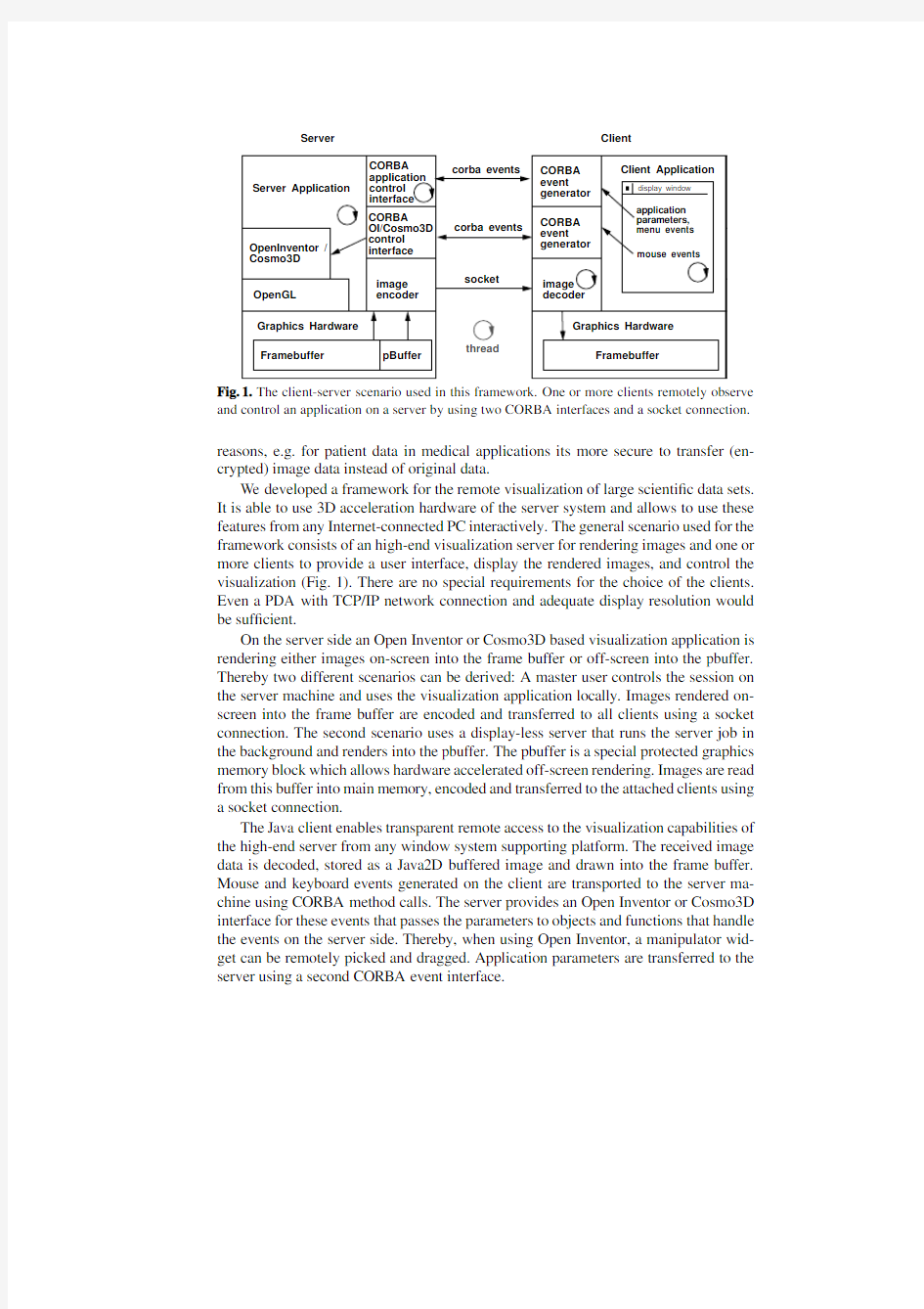
Server Client
Fig.1.The client-server scenario used in this framework.One or more clients remotely observe and control an application on a server by using two CORBA interfaces and a socket connection. reasons,e.g.for patient data in medical applications its more secure to transfer(en-crypted)image data instead of original data.
We developed a framework for the remote visualization of large scienti?c data sets. It is able to use3D acceleration hardware of the server system and allows to use these features from any Internet-connected PC interactively.The general scenario used for the framework consists of an high-end visualization server for rendering images and one or more clients to provide a user interface,display the rendered images,and control the visualization(Fig.1).There are no special requirements for the choice of the clients. Even a PDA with TCP/IP network connection and adequate display resolution would be suf?cient.
On the server side an Open Inventor or Cosmo3D based visualization application is rendering either images on-screen into the frame buffer or off-screen into the pbuffer. Thereby two different scenarios can be derived:A master user controls the session on the server machine and uses the visualization application locally.Images rendered on-screen into the frame buffer are encoded and transferred to all clients using a socket connection.The second scenario uses a display-less server that runs the server job in the background and renders into the pbuffer.The pbuffer is a special protected graphics memory block which allows hardware accelerated off-screen rendering.Images are read from this buffer into main memory,encoded and transferred to the attached clients using a socket connection.
The Java client enables transparent remote access to the visualization capabilities of the high-end server from any window system supporting platform.The received image data is decoded,stored as a Java2D buffered image and drawn into the frame buffer. Mouse and keyboard events generated on the client are transported to the server ma-chine using CORBA method calls.The server provides an Open Inventor or Cosmo3D interface for these events that passes the parameters to objects and functions that handle the events on the server side.Thereby,when using Open Inventor,a manipulator wid-get can be remotely picked and dragged.Application parameters are transferred to the server using a second CORBA event interface.
Using our framework,which consists of several C++and Java classes,the client and server applications can be easily developed.Moreover the framework enables the conversion of any existing visualization application into a remotely controllable one by adding only a small amount of additional code.Multiple clients are able to share the view on the data and interact in turn.
In the following section we will describe some related work in the?eld of web based visualization.Section3outlines the architecture of our framework.Section4explains two exemplary applications which use the proposed techniques.Results are given in section5.We will conclude the paper with some remarks on future activities.
2Related Work
In the past years several approaches for scienti?c visualization on digital networks were investigated.One of the?rst progressive applications for volume visualization was pre-sented by Lippert et al.[7].
Hendin introduced a VRML based volume visualization tool[5],which uses three stacks of perpendicular slices.We introduced techniques for fast volume clipping,col-laborative work,and data size reduction[2]as an extension to Hendin’s approach.
An opposite approach was proposed by Ma et al.The web based volume visualiza-tion system called DiVision allows users to explore remote volumetric data sets using a web-browser[10].The system computes images on a visualization server,which are transferred to the client and inserted into a graph.However,the application does not support interactive manipulation.
In the virtual network computing(VNC)system by Richardson et al.[11],server machines supply applications,data,and desktop environments that can be accessed from any Internet-connected machine using a wide variety of machine architectures.It is a remote display system which allows the user to view a computing desktop environ-ment from anywhere on the Internet.VNC does not support to use remote3D graphics acceleration hardware.
Just recently SGI announced OpenGL Vizserver[8].From the limited amount of information which is currently available it is understood that OpenGL Vizserver will enable a single Onyx2workstation to distribute visualization sessions to multiple UNIX operating system desktop workstations by transmitting compressed images from the Onyx2frame buffer.While the system only seems to work inside organization networks and only on SGI machines,our framework allows transparent access to any high-end server from any Internet-connected desktop PC.
3The Framework
The framework consists of several C++classes for the server side and Java modules that are used to build a client application.Because of the modular structure of the framework it can be applied to any visualization application and new codecs can be added.
3.1Server modules
A stand-alone visualization application can easily be converted into a remotely accessi-ble one by adding a CORBA interface and slightly modifying the scene graph.Currently the framework was adapted for Open Inventor and Cosmo3D.
Open Inventor:Open Inventor traverses the scene graph in a?xed order from top to bottom and left to right.Because of this behavior we can add a new scene graph node named PBufferNode that switches to the pbuffer rendering context in front(to the left)of the contributing nodes,generally at the leftmost position.The SocketNode reads the frame buffer content into main memory and performs the encoding and trans-mission of the image data.It is inserted behind(to the right)of the contributing nodes, generally at the rightmost position in the scene graph.
As soon as the scene graph has changed or new mapping parameters(e.g.modi?ed transfer functions)have been received a render action is applied to the root node of the scene graph.Then the following sequence of steps is performed:
1.The render action traverses the scene graph from top to bottom and left to right.
2.As soon as the PBufferNode is reached,the render method switches to the
pbuffer rendering context.If there was no PBufferNode node added to the scene graph the rendering context remains on-screen.
3.The render action continues to traverse through the scene graph and the shape nodes
draw geometry into the current rendering context.
4.As soon as the SocketNode is visited,the content of the frame buffer is read into
main memory.It compresses the image data using one of the available compression methods and provides the encoded data to all connected clients via a given socket port.
5.The render action continues to traverse the scene graph.
Open Inventor provides convenient mechanisms to convert2D events received from
a client to3D events.The steps that are performed can be summarized as follows:
1.The client application registers interest in particular events with its window system.
2.The client application receives an event from its window system.
3.The client calls the appropriate server method using CORBA and delivers the nec-
essary parameters(e.g.mouse position,mouse button)to the server.
4.The server application translates the event into a SoEvent(for mouse events
SoLocation2Event).
5.The SoEvent is inserted into an instance of the SoHandleEventAction class.
6.The handle event action is applied to the top node of the scene graph.This action
traverses the scene graph.Each node implements its own action behavior.When a node(typically a manipulator)is found,it handles the event.
7.If necessary a render action is applied to the scene graph.
The CORBA main loop and the Open Inventor main loop are running in two sepa-rate threads.As Open Inventor is not thread-save the received client events can not be applied to the scene graph immediately.The Ticker class is an Open Inventor engine (derived from SoEngine)that stores SoHandleEventAction s created by client event receiving CORBA methods.The Ticker class is called from the Open Inventor main loop in?xed time steps and triggers a SoHandleEventAction.
Cosmo3D:The scene graph structure provided by Cosmo3D differs from that of Open Inventor.No information is inherited horizontally in the Cosmo3D scene graph,which is traversed downwards from top to bottom in each branch.OpenGL Optimizer offers different kinds of scene graph traversal actions:On the one hand there are depth-?rst traversal actions which do their work in the same order as Open Inventor actions do. On the other hand breadth-?rst traversal actions can be applied for parallelization using multiple processors.Thus,a new Cosmo3D scene graph node,which implements the corresponding functionality of the described PBufferNode and SocketNode,is derived from the Cosmo3D class csGroup.Its method drawVisit()contains a pre-and a post-traversal section.The former switches the rendering context to pbuffer while the latter section starts the encoding and transmission of the image data.
In contrast to the Open Inventor scenario the new Cosmo3D scene graph node is used as a root node which enfolds the original scene graph as its subgraph.
Alternatively,the scene graph can be left untouched and just one function call has to be added at the beginning of the method opXmViewer::swapBuffers().This function determines the current drawing buffer,calls glReadPixels()and initiates the image encoding and transmission.
Incoming mouse or key events are interpreted and handled after a pre-processing step by the corresponding methods in the opXmViewer class as if they had been ap-peared on the local site.For example,mouse events are sent to a method which con-verts the incoming data and emulates the method processPendingEvents()of opXmViewer.
3.2Client modules
The client modules are implemented using the JA V A2platform.We provide the follow-ing classes:
RenderArea:The basic render area vis.inventor.RenderArea is a drawing area for frame buffer content,that was received from the visualization server.For this purpose the Java2D java.awt.image.BufferedImage class is used.The draw-ing area also relays mouse events that are sent to the server.It is derived from the java.awt.Panel class and can be added into any Java container.The
vis.inventor.FullViewer class,derived from this class,provides the look-and-feel and functionality of Open Inventors SoXtFullViewer,which includes a decora-tion around the render area.This decoration is make up out of thumb wheels,sliders,and push buttons.It also supports a context menu that allows to change the Open Inventor rendering type in several ways.
Decoders:vis.imagedecoder.Decoder is the abstract base class for all codecs we have implemented.New decoders can be integrated into the framework by deriving new classes from this base class.We provide the decoders
vis.imagedecoder.ZLIBDecoder,vis.imagedecoder.LZODecoder, vis.imagedecoder.RLEDecoder and vis.imagedecoder.RAWDecoder.
time
apply
read frame latency
Fig.2.The latency in between manipulation and image update consists of request,event transla-tion,rendering,frame buffer read,encoding,transfer,decoding and display time.
SimpleViewer:We also provide a class vis.viewers.SimpleViewer which can be used as a client to observe any remote visualization session of an application that was adapted using our framework.For this purpose only some lines of code have to be added to a stand-alone visualization application.
3.3Network Communication
The transmission of images and the remote control of the server application are strictly decoupled.The image data is streamed through a TCP socket connection and the ap-plication,mapping and rendering parameters are applied to the server application by using CORBA method calls.Once new mapping or rendering parameters were received by the server they are applied to the visualization.Then the rendering is performed,the frame buffer is copied into main memory,the data is encoded,transferred to the clients,decoded and ?nally copied into the frame buffer of the client (Fig.2).These steps determine the overall latency of the application between manipulation and image update.
CORBA interfaces:The CORBA interface to the server is divided up into two parts:–The events for the render area of the server application are sent to the server using the interface RenderArea .For a server that uses Open Inventor the interface FullViewer extends the RenderArea interface with functionality of the Open Inventor SoXtFullViewer class.
–Application speci?c parameters are accessed via the Application interface.We provide a base interface which can be extended to make the functionality of a server application accessible.For example,if the application allows to add clipping planes we would have to add a method addClippingPlane to the interface and imple-ment the appropriate server method.
Image compression and transfer:The image transmission is decoupled from the CORBA interfaces because we wanted to be able to quickly replace the image transfer
codec with more sophisticated ones without any changes in the remaining networking code.It could be as well integrated into the CORBA communication,but right now we transfer the image data using a TCP socket connection.The user can select one of following encoding types:
–RA W:The codec returns the original data,thus no compression is performed.This method can be used in a high bandwidth network to keep the latency low.
–ZLIB:Performs a loss-less compression based on the ZLIB library[12].The algo-rithm?nds duplicated strings in the input data.The second occurrence of a string is replaced by a pointer to the previous string,in the form of a pair(distance,length).
ZLIB compression is a standard feature of Java since version1.1and is performed via fast native code.
–LZO:Performs a loss-less compression based on the LZO library[9].LZO is a block compression algorithm-it compresses and decompresses a block of data.
Block size must be the same for compression and decompression.LZO compresses
a block of data into matches(a sliding dictionary)and runs of non-matching literals.
LZO favors speed over compression ratio.As the LZO codec is not a standard method of Java,the LZO decompression is accessed via a Java Native Interface (JNI)call.
–RLE:Performs a loss-less compression based on run-length encoding.
Despite of the image compression the amount of data that has to be transmitted to the client is still too large for low-bandwidth network connections like an ISDN connection.In order to allow high interaction rates on such connections we additionally apply an image size reduction while interacting with the data.For example,when a manipulator is picked and dragged we transfer the images with half or quarter resolution and scale the images to full size on the client.As soon as the user stops dragging the manipulator a full frame is transmitted.The combination of compression and image size reduction provides suf?cient frame rates even on56k modem network connections.
4Collaborative visualization environments
In areas where specialists are separated by distance the work-?ow ef?ciency can be improved by collaborative applications.For example,such applications allow users to discuss the visualized data sharing the same view.Furthermore,expensive experts can be consulted and distance education or advanced training can be held.Additionally,our approach provides simultaneous access to a server application for multiple users.Thus the capabilities of expensive hardware can be sharded by low-cost client systems.
In this section we will present two applications that were extended by our frame-work to enable collaborative work.The?rst one is an application that uses3D texture mapping hardware of high-end graphics workstations to visualize medical volume data. The second one is employed in the car development process for visualization of huge time-dependent?nite element models.
4.1Teleradiology
The use of3D texture mapping hardware has become a powerful visualization option for direct volume rendering[1,15].Unfortunately,up to now3D texture mapping hardware
is still restricted to high-end graphics workstations.Now one can make the hardware capabilities accessible to almost any client system by using our framework.
For this purpose an interactive stand-alone texture based rendering application for medical volume data has been extended(Fig.3,left).It has been integrated into the Open Inventor framework in order to obtain the whole?exibility and functionality of-fered by this graphics API.By introducing a new class,the volume renderer has been represented as a separate object within the hierarchical structure of the scene graph. This allows convenient use of built-in manipulators,sensors,editors and other prede-?ned classes,methods and features(light sources,anti-aliasing,perspective/orthogonal projection,?y,walk,trackball)[4,13].
First a few lines of code were added in order to extend the scene graph using the SocketNode we previously introduced.With this small modi?cation it is possible to join a visualization session passively using a web-browser and observe the visualization. To allow remote control of the application we had to extend the base CORBA applica-tion interface with additional functionality(e.g.update of transfer function,adding of clipping planes,etc.).On the client side a viewer application was developed that pro-vides the same look-and-feel as the stand-alone application(Fig.3,right).We used the vis.inventor.FullViewer class as the display area in the main window,added some buttons to the decoration,and reimplemented the menu bar and the dialogs of the stand-alone application in Java(e.g.the transfer-function dialog).
Recapitulating,our approach allows working groups to discuss medical volume data sets collaboratively.3D texture supporting graphics workstations,which were too ex-pensive for many hospitals,can now be used remotely from any desktop PC.No patient data is transferred through the network and the security of the image stream can be ensured by using SSH socket tunneling.
4.2Visualization of crash-worthiness simulations
Another example where the presented technique is very useful is the visualization in the car development process.In cooperation with the BMW Group we developed a Cosmo3D/OpenGL Optimizer based application which is in productive use in the pre-and post-processing of crash-worthiness simulations.
The car bodies are represented by about500.000mainly four-sided?nite elements. During simulation the?rst120ms are computed and the coordinates of the deforming mesh are stored in60time steps together with the tracked parameters into a result?le. Those result?les often contain more than1.5GB of data.
Our application crashViewer builds a Cosmo3D scene graph that describes the car body for each time step.We developed an OpenGL Optimizer based viewer which allows the engineer to visualize and animate the crash.Furthermore,the crash perfor-mance can be analyzed by directly mapping the tracked scalar parameters as colors onto the geometry or by visualizing the force?ux by force tubes[6].
To represent the large scale Gouraud-shaded time-dependent geometry with con-stant topology for each time step in a Cosmo3D scene graph,as proposed in[14],ap-proximately700MB of main memory is required.Since only high-end graphics work-stations are equipped with such a lot of main memory a technique was sought to make
those expensive resources accessible to low-end systems.Hence,we extended the stand-alone visualization application by our approach which offers a solution by transferring image data from any OpenGL supporting workstation to arbitrary window supporting client systems.
If a meeting of the analyzing engineers is too time-consuming because they are,for example,located at distant sites,the image transfer allows for a collaborative discussion on the crash-worthiness of the current model variant.One engineer starts the visualiza-tion application which is able to provide the rendered images in encoded data stream form as previously outlined.
There are two scenarios:?rst,the other engineer starts a Java application that offers a minimal set of functionality of the original C++-based visualization application.2D mouse events and keystrokes triggered on the client side are transmitted back to the server application and interpreted there like described in section3.1.In the second sce-nario where one engineer will communicate some results to one or more engineers who do not have to interact with the model the former one advises an URL to other partic-ipants.They start any HTML browser,download a HTML page from the given URL which includes a Java applet(see Fig.4).This applet encapsulates the SimpleViewer described in section3.2.
Summarizing,our approach allows collaborative working groups to discuss simula-tion results in distributed heterogeneous environments.There are low requirements to participating client systems.Additionally,in regard to security aspects,for example,if third party engineers of subcontractors are involved,the pure data will stay in-house; instead just image data is transferred.We expect,that this technique will facilitate the collaboration between accordant working groups of BMW and Rover,where it will be tested in the next few months.
5Results
In this section we show results for the proposed techniques.On the server side all tests were run on a SGI Onyx2workstation equipped with two195MHz R10000processors and512MB of main memory.A SGI O2workstation with the same processor and 128MB of main memory and a333MHz Celeron PC equipped with64MB of main memory were serving as the client systems.The O2was linked via a100MBit Ethernet network connection and the PC was linked using a64kBit ISDN Internet connection. We used the medical volume visualization environment with a512x512x106CT data set.A typical image sequence with frames of704pixels width,576pixels height and 24bits depth was used.
First we analyze the frame rates that can be achieved over the local network and the Internet connection(Table1).While interacting with the volume the images were rendered and transferred at quarter resolution(176x144pixels),after interaction a full frame was transmitted.This leads to faster rendering,encoding,transfer,decoding and display times.When using the stand-alone non-networked visualization application we achieved an average frame rate of4.1for the full frames and25.4frames per second for quarter https://www.360docs.net/doc/347784498.html,ing the ISDN connection no interactive rates were achieved us-ing full frames.This is negligible during interaction because then we are transferring
LAN
method
quarter full full full RAW
76kb 1.9-106kb
14 1.5
LZO
9kb 4.1 2.40.06160kb 16 1.2Table 1.The listed frame rates were achieved when visualizing a CT data set (512x512x106)locally,remotely using ISDN and remotely in a LAN network.Quarter resolution frames (176x144pixels)were sent while interacting with the volume and full resolution frames (704x576pixels)were sent after interaction.The average amount of transferred data for a full and quarter sized frame is denoted in the left part of the table.
quarter sized images only.Thus interactive refresh rates could be achieved.Only if the user stops to interact (e.g.releases a manipulator)the user has to wait some seconds for the full size frame.Best frame rates were achieved using ZLIB compression because the network bandwidth is the limiting factor for transmission via ISDN.We will see later that ZLIB compression has the best compression ratio.For a local network con-nection best frame rates were achieved using RLE compression because the encoding and decoding times are the critical values.
Secondly,we compare the encoding time and the compression ratios when using ZLIB,RLE and LZO compression.The average encoding time was 180milliseconds for ZLIB,50milliseconds for LZO and 30milliseconds for RLE.The average decoding time on the O2was 93milliseconds for ZLIB,29milliseconds for LZO and 13millisec-onds for RLE.Obviously,concerning the compression ratio ZLIB compression is ahead of the other compression methods (Fig.5).RLE performs nearly as well as LZO com-pression.RLE is the simplest and thus the fastest compression method we investigated.The compression ratios of all methods of course depend on the covering of the screen space by the visualization.That is why a magni?cation leads to lower compression fac-tors.Because of these results we currently favour ZLIB compression on low bandwidth channels and RLE compression on high bandwidth channels.
6Conclusions and Future Work
We have presented a framework which allows remote high-end visualization from any Internet-connected,Java-enabled desktop PC.The introduced techniques were demon-strated by two applications.A volume renderer for 3D medical data,that uses special 3D texture hardware,can now be used remotely from any Internet-connected PC.We will effect an application study with the Department of Neurosurgery of the Univer-sity of Erlangen-Nuremberg.Furthermore,a visualization application for large scale data sets of crash-worthiness simulations was extended by the presented framework to enable collaboration in the car development process.
As a main result of our work it is now possible to remotely explore huge scienti?c data sets on specialized server hardware using low-cost clients.We showed that this is even possible using a low bandwidth channel like an ISDN connection.The trans-fer of GUI events and application parameters requires a much lower bandwidth than
the download of rendered images.Exactly this scenario is given while using low-cost broadband Internet connections like cable modems or satellite connections.
An area of future work involves the development of specialized image-streaming codecs for computer generated image sequences.First results using video streaming codecs were presented in[3].However,currently available codecs are based on the needs of Internet video streams.Those streams have different characteristics than ren-dered ones(variable frame rate,partial changes in consecutive frames,...).One pos-sible approach would be to use lossy compression while interacting with the data and loss-less compression when having still images.Also image encryption techniques are necessary for transferring sensitive data over the Internet.
References
1. B.Cabral,N.Cam,and J.Foran.Accelerated V olume Rendering and Tomographic Recon-
struction Using Texture Mapping Hardware.In A.Kaufman and W.Kr¨u ger,editors,1994 Symposium on Volume Visualization,pages91–98.ACM SIGGRAPH,1994.
2.K.Engel and T.Ertl.Texture-based V olume Visualization for Multiple Users on the World
Wide Web.In5th Eurographics Workshop on Virtual Environments,1999.
3.Klaus Engel,Ove Sommer,Christian Ernst,and Thomas Ertl.Remote Visualization us-
ing Image-Streaming Codecs.In Proceedings of Symposium on Intelligent Multimedia and Distance Education,Baden-Baden,Germany,August1999.
4.P.Hastreiter,H.K.C?akmak,and Th.Ertl.Intuitive and Interactive Manipulation of3D Data
Sets by Integrating Texture Mapping Based V olume Rendering into the OpenInventor Class Hierarchy.In K.Spitzer Th.Lehman,I.Scholl,editor,Bildverarbeitung fuer die Medizin: Algorithmen,Systeme,Anwendungen,pages149–154.Inst.f.Med.Inf.u.Biom.d.RWTH, Aachen,Verl.d.Augustinus Buchhandlung,1996.
5.Ofer Hendin,Nigel John,and Ofer Shochet.Medical V olume Rendering Over the WWW
using VRML and JA V A.In Proceedings of MMVR,1997.
6.S.Kuschfeldt,O.Sommer,T.Ertl,and M.Holzner.Ef?cient Visualization of Crash-
Worthiness Simulations.IEEE Computer Graphics and Applications,18(4):60–65,1998.
7.L.Lippert,M.H.Gross,and https://www.360docs.net/doc/347784498.html,pression domain volume rendering for dis-
tributed environments.In Proceedings Eurographics’97,pages C95–C107,1997.
8.SGI Newsroom.SGI Brings Advanced Visualization to the Desktop with OpenGL Vizserver.
https://www.360docs.net/doc/347784498.html,/software/vizserver/.
9.M.F.X.J.Oberhumer.Lzo.http://wildsau.idv.uni-linz.ac.at/mfx/lzo.html.
10.J.Patten and K.-L.Ma.A Graph Based Approach for Visualizing V olume Rendering Results.
In Proc.of GI’98Conference on Computer Graphics and Interactive Techniques,1998. 11.T.Richardson,Q.Stafford-Fraser,K.R.Wood,and A.Hopper.Virtual Network Computing.
IEEE Internet Computing,2(1),January1998.
12.G.Roelofs.Zlib.https://www.360docs.net/doc/347784498.html,/pub/infozip/zlib/.
13.O.Sommer,A.Dietz,R.Westermann,and T.Ertl.An Interactive Visualization and Naviga-
tion Tool for Medical V olume Data.In V.Skala,editor,Proc.6th International Conference in Central Europe on Computer Graphics and Visualization’98,pages362–371,1998. 14.Ove Sommer and Thomas Ertl.Geometry and rendering optimizations for the interactive
visualization of crash-worthiness simultations.In Proceedings of SPIE,Visual Data Explo-ration and Analysis VII,volume3960,January2000.to appear.
15.R¨u diger Westermann and Thomas Ertl.Ef?ciently Using Graphics Hardware in V olume
Rendering Applications.In Computer Graphics Proceedings SIGGRAPH’98,Annual Con-ference Series,pages169–177.ACM SIGGRAPH,July1998.
Fig.3.Transparent remote access to 3D texture mapping hardware of a C++server application (on the left)from a Java client application (on the right).Note that the client provides the same look-and-feel as the stand-alone application by providing an Open Inventor-like decoration.The displayed manipulators can be picked and dragged remotely.
Fig.4.Transfer of image data from the original visualization application (on the left)via a socket connection to a HTML browser (on the right).
https://www.360docs.net/doc/347784498.html,pression Ratios of ZLIB,LZO and RLE compression for a typical image sequence.A rotation of the volume followed by a magni?cation was performed.