High-temperature oxidation of nano-multilayered TiAlCrSiN thin films in air
High-temperature oxidation of nano-multilayered TiAlCrSiN thin ?lms in air
Thuan Dinh Nguyen a ,Sun Kyu Kim b ,Dong Bok Lee a ,?
a School of Advanced Materials Science and Engineering,Sungkyunkwan University,Suwon,440-746,South Korea b
School of Materials Science and Engineering,University of Ulsan,Ulsan,680-749,South Korea
a b s t r a c t
a r t i c l e i n f o Article history:
Received 28July 2009
Accepted in revised form 2September 2009Available online 11September 2009Keywords:
Nanolayered ?lm TiAlCrSiN
Cathodic arc plasma deposition Oxidation
Nano-multilayered TiAlCrSiN ?lms consisting of alternating,crystalline TiCrN and AlSiN nanolayers were deposited by cathodic arc plasma deposition.Their oxidation characteristics were studied between 600and 1000°C for up to 70h in air.The formed oxides consisted primarily of Cr 2O 3,α-Al 2O 3,SiO 2,and rutile-TiO 2.The TiAlCrSiN ?lms oxidized slower than the TiN ?lms and faster than the CrN or CrAlSiN ?lms,with an apparent activation energy of 36.4kJ/mol.During their oxidation,an outermost TiO 2layer was formed by outward diffusion of Ti ions,and the outer Al 2O 3layer was formed by outward diffusion of Al ions.Simultaneously,an inner (Al 2O 3,Cr 2O 3)-mixed layer and an innermost TiO 2layer were formed by the inward diffusion of oxygen ions.SiO 2was present mainly in the lower part of the oxide layer due to its immobility.
?2009Elsevier B.V.All rights reserved.
1.Introduction
Transition metal nitride ?lms such as TiN and CrN are widely used for cutting tools or die molds because of their high hardness and superior resistance to wear and corrosion,however they are inevitably degraded by oxidation during service at high temperatures.TiN oxidizes rapidly above 550°C with the formation of a TiO 2layer [1],whereas CrN oxidizes rapidly to Cr 2O 3above 700°C [2].The oxidation of nitrides is always accompanied by the liberation of nitrogen.To further increase the oxidation resistance and mechanical properties,TiAlN [1],TiCrN [3],TiSiN [4],TiAlSiN [5],CrSiN [6],CrAlN [7],CrAlSiN [8,9],and TiCrAlSiN [10–16]?lms were developed.TiCrAlSiN ?lms are a recent development for enhanced high tempera-ture performances,and their microhardness,microstructures,and cutting properties were previously studied [10–16].Their thermal stability was examined by annealing in a vacuum for 2h between 800and 1100°C [10,11],or oxidizing in air for 0.5–2h between 800and 1000°C [12,14,15].The thermal stability of the ?lms depends sensitively on the deposition method and parameters that affect their crystallinity,composition,stoi-chiometry,thickness,surface roughness,grain size and orientation.Hence,it is necessary to study the high-temperature oxidation behavior of the TiAlCrSiN ?lms under diverse oxidizing conditions for wide applications.In this study,TiAlCrSiN ?lm consisting of alternating Ti(Cr)N/Al(Si)N nano-multilayers was deposited on a steel substrate by cathodic arc plasma process.It is important to note that nano-multilayered ?lms are of increasing interest due to their superior mechanical and lubrication properties in advanced tribological applications where single layer ?lms are insuf ?cient.The purpose of this study is to investigate the oxidation behavior of nano-multilayered TiAlCrSiN thin ?lms,which was not yet studied.In this study,the oxidation conditions were
expanded to a temperature range between 600and 1000°C for up to 70h in air.The oxidation kinetics was studied using a thermogravimetric analyzer (TGA)and compared to other ?lms.The oxidation mechanism was proposed by performing Au-marker tests.Transmission electron microscopic (TEM)analyses were performed to investigate the scale morphology in detail.2.Experimental details
TiAlCrSiN ?lms were deposited on SKD11tool steel (1.5%C,11.5%Cr,0.8%Mo,0.9%V)with dimensions of 10×5×2mm 2by cathodic arc plasma deposition [16].A 70at.%Ti –30at.%Cr alloy and 88at.%Al –12at.%Si alloy were used for cathodes.The ?lms were deposited on both sides of the steel substrate at a nitrogen pressure of 4Pa,a temperature of 300°C,a bias voltage of ?100V,Ti –Cr cathode arc current of 55A and Al –Si cathode arc current of 50A.The substrate holder was rotated at 4.55rpm during deposition.By rotating the substrate between two opposing cathodes of Ti –Cr and Al –Si alloys,nano-multilayered TiAlCrSiN ?lms were deposited.
The TiAlCrSiN ?lms deposited on the steel substrates were oxidized between 600and 1000°C for up to 70h in air using a TGA (ThermoCahn 2141).Each sample was suspended by a platinum wire in an alumina reaction tube within the hot zone of the MoSi 2furnace.The TiAlCrSiN ?lms were characterized by an X-ray diffractometer (XRD;Mac Science M18XHF-SRA)with Cu-K αradiation,X-ray photoelectron spectrometer (XPS;ESCA2000),Auger electron spectrometer (AES;Perkin-Elmer l660),electron probe microanalyzer (EPMA;Jeol JXA-8900R),and TEM (Jeol JEM-2100F operated at 200keV)equipped with an energy dis-persive spectrometer (EDS with 5nm spot size).The TEM sample was prepared by milling in a focused-ion-beam (FIB;SII SMI3050TB)system with a liquid-gallium-metal ion source and maximum accelerating vol-tage of 30kV.
Surface &Coatings Technology 204(2009)697–704
?Corresponding author.Tel.:+82312907355;fax:+82312907371.E-mail address:dlee@skku.ac.kr (D.B.
Lee).0257-8972/$–see front matter ?2009Elsevier B.V.All rights reserved.doi:
10.1016/j.surfcoat.2009.09.008
Contents lists available at ScienceDirect
Surface &Coatings Technology
j o u r n a l h om e p a g e :w w w.e l s ev i e r.c o m /l o c a t e /s u r fc o a t
3.Results and discussion
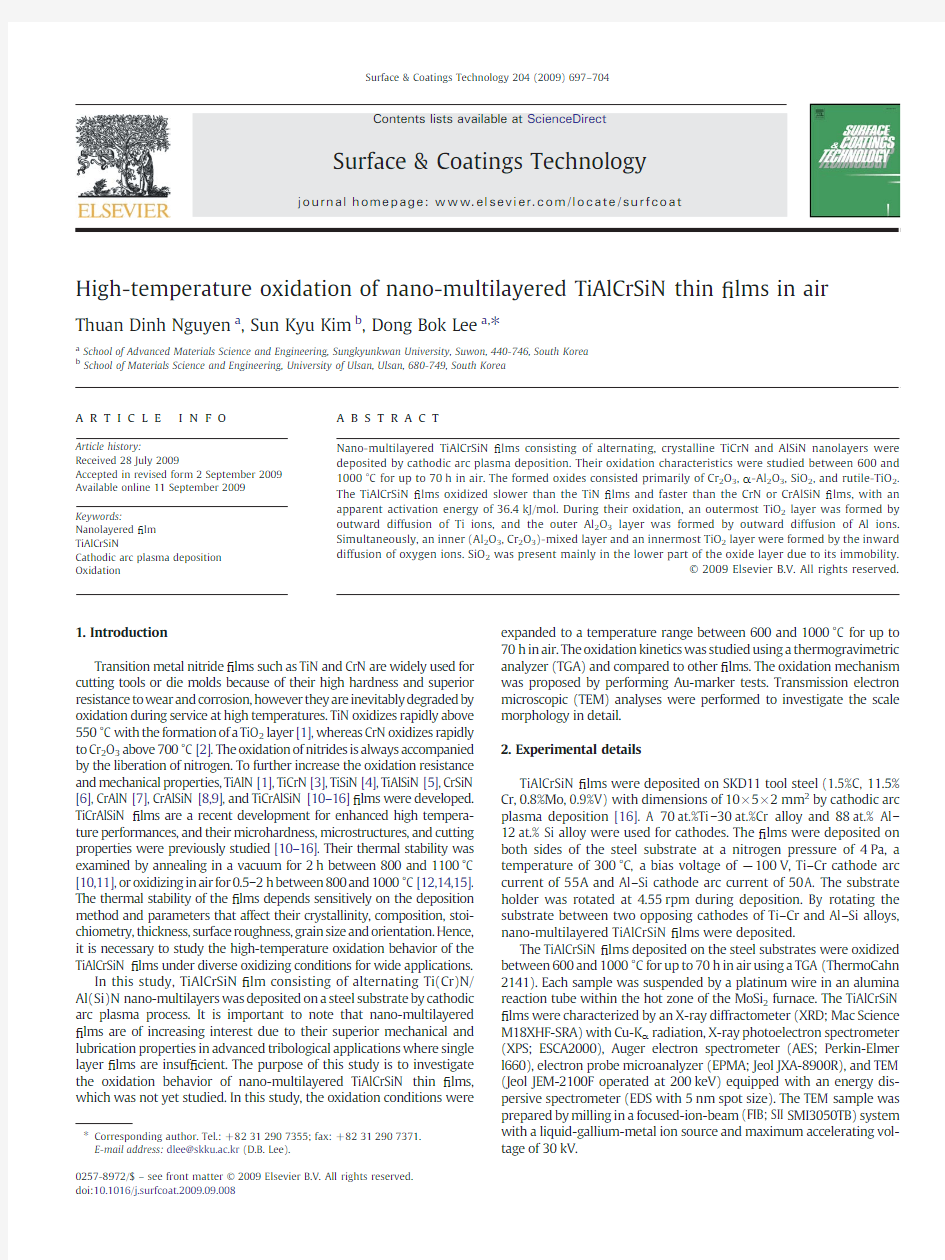
Fig.1shows the analytical results of the as-deposited TiAlCrSiN ?lm.The SEM top view displays a featureless,smooth ?lm surface,with a few microdroplets (Fig.1a).The EPMA cross-sectional image indicates that the ?lm was dense,adherent,and approximately 5μm thick (Fig.1b).The corresponding EPMA line pro ?les indicated that Ti,Al,Cr and Si were uniformly distributed in the ?lm (Fig.1c).However,the TEM cross-sectional image of the ?lm reveals a nano-multilayered structure (Fig.1d).It was previously observed by EDS analysis that the white layers were TiCrN (width=4.5nm)and the dark layers were AlSiN (width=11.5nm)[16].The selected area electron diffraction (SAED)pattern of the white and dark layers in Fig.4d consisted of Debye rings superimposed with spots,as is typical for polycrystalline materials (Fig.1e).The white and dark layers matched the crystalline fcc -TiN (JCPDS-number;87-0633)and hcp -AlN (JCPDS-number;79-2497),respectively.The incorporation of Cr in the TiN phase and that of Si in the AlN phase did not appreciably change the position of the TiN and AlN Debye rings as the amount of Cr and Si in the ?lm was small.According to the AES analysis,the average ?lm composition was 13.5Ti –9.3Al –5.9Cr –1.5Si –69.8N (at.%).The phase identi ?cation by XRD shows the presence of crystalline TiN in the ?lm (Fig.1f).Here,the substrate peaks were also observed due to the thinness of the ?lm.The TiN peaks in Fig.1f were weak and broad because the ?lm was nanocrystalline and multilayered.These effects are also the reason for the absence of other phases in Fig.1f,such as Al(Si)N.In the case of XRD analyses,the X-ray beam scatters more when the grains are ?ne.
Fig.2shows the weight gain versus oxidation time curves and corresponding parabolic plots of the TiAlCrSiN ?lm deposited on the steel substrate.The measured weight gains were small and increased with increasing oxidation temperature (Fig.2a).The oxidation kinetics did not strictly follow the familiar parabolic rate law,mainly due to the initial,fast oxygen up-take and continuous release of nitrogen dur-ing scaling.After excluding the initial 2.5h of the transient oxidation period,the parabolic rate constant,k p ,was calculated from Fig.2b using (ΔW /A )2=k p ·t ,where ΔW /A is the weight gain per surface area of the specimen,and t is the exposure time.
In Fig.3,the k p values of the TiAlCrSiN ?lm were compared with other published data [9,17–21].It is noted that the factors that can affect the k p values of the TiAlCrSiN ?lm were the oxidation of constituting elements,the release of nitrogen,and the subsidiary oxidation of sub-strate elements that could be diffused into the TiAlCrSiN ?lm
according
Fig.1.TiAlCrSiN ?lm deposited.(a)SEM top view of the ?lm,(b)EPMA cross-sectional image of the ?lm and the substrate,(c)EPMA line pro ?les along A –B shown in (b),(d)cross-sectional bright ?eld TEM image of the ?lm,(e)SAED pattern of the ?lm,and (f)XRD pattern of the ?lm deposited on the steel.
698T.D.Nguyen et al./Surface &Coatings Technology 204(2009)697–704
to the concentration gradient during oxidation at high temperatures.The TiAlCrSiN ?lm oxidized slower than the TiN ?lms [20,21]due to the presence of Al,Cr,and Si.However,TiAlCrSiN oxidized faster than the CrN ?lms [20,21],mainly due to the presence of Ti.It is noted that Al,Cr,and Si form extremely protective Cr 2O 3,Al 2O 3,and SiO 2,respectively,while Ti forms semi-protective TiO 2.Hence,the oxidation resistance of the CrAlSiN ?lm [9]decreases with the addition of Ti [14].The TiAlCrSiN
?lm oxidized slower than the TiO 2-forming kinetics [18],but faster than the α-Al 2O 3-forming kinetics [19].The overall oxidation rate of the TiAlCrSiN ?lm was comparable to the Cr 2O 3-and SiO 2-forming kinetics [17].The apparent activation energy,Q (kJ/mol),for the oxidation of the TiAlCrSiN ?lm from Fig.3was 36.4,which was smaller than those of 187–198,98–251and 270reported for the oxidation of TiN ?lms [22],CrN ?lms [23],and CrAlSiN ?lm [9],respectively.The Q value in this study was mainly related to the diffusion process of ions through TiO 2,Al 2O 3,Cr 2O 3,and SiO 2,and the release of nitrogen through the oxide scale.In Fig.3,the relatively low k p and Q value of the TiAlCrSiN ?lm imply that the oxidation rate is slow and less sensitive to the oxidation temperature.
Fig.4shows the Ellingham diagram of the oxides that can be formed on the TiAlCrSiN ?lm [24].The oxide stability increases in the order of Cr 2O 3,SiO 2,TiO 2,TiO,and Al 2O 3.The most active aluminum oxidized to α-Al 2O 3in this study.This oxide grows very slowly due to the high stoichiometry.Titanium is slightly less active than aluminum and the transient oxides are TiO,Ti 2O 3,and the Magneli phases,with the general formula,Ti x O 2x –1[25].In this study titanium oxidized rapidly to rutile-TiO 2.The third most active element is Si,which usually oxidizes to the extremely protective SiO 2and has a low diffusivity for both anions and cations due to its high degree of stoichiometry.The most noble element,Cr,oxidizes to Cr 2O 3with a high degree of stoichiometry.
Fig.5shows the XPS spectra of the TiAlCrSiN ?lm before and after oxidation.In Fig.5a,the intensity of the spectra decreased in the following order;N 1s >Ti 2p >Al 2p ≈Cr 2p >Si 2p ,which was plausible considering the average ?lm composition was 13.5Ti –9.3Al –5.9Cr –1.5Si –69.8N (at.%).The Ti 2p3/2peak was centered at 456.8eV,which was larger than the Ti 2p3/2binding energy of TiN (455.8eV).This deviation in the binding energy may be due to the presence of Cr in the TiN layers as Ti(Cr)N.The Al 2p spectrum showed a component at 73.6eV between the Al 2p binding energy of free aluminum (72.9eV)and AlN (74.3eV).This deviation may be due to the presence of Si in the AlN layers as Al(Si)N in the ?lm.The Cr 2p3/2peak was centered at 575.4eV,which might be associated with CrN.The peaks pertaining to free chromium (574.4eV)and Cr 2N (574.5eV)were not recognizable.The Si 2p spectrum showed a component with a binding energy at 101.4eV,indicating chemical bonding of SiN x .Silicon was previously found to exist in the form of hcp -AlSiN [11],fcc -TiAlSiN [12],fcc -TiCrAlSiN [10,13,15],or amorphous AlSiN [16],depending on the composition and structure of the (Ti,Cr,Al,Si)N ?lms.In this study,the N 1s spectrum showed a binding energy component at 396.6eV associated with the nitrides.
Fig.5b shows the XPS spectra of the TiAlCrSiN ?lm after oxidation at 900°C for 20h.The intensity of the spectra of the outermost oxides decreased in the following order;O 1s >Ti 2p >Cr 2p >Al 2p >Si 2p >N 1s .The binding energies of Ti 2p3/2,Al 2p ,and Cr 2p3/2peaks were centered at 458.4,74.3,and 577.1eV,which may be mostly associated with TiO 2
,
Fig.2.Oxidation kinetics of the TiAlCrSiN ?lm at 600,700and 800°C in air.(a)Weight gain vs.oxidation time curves and (b)parabolic
plot.
Fig.3.Arrehnius plot of k p vs.1/T for the TiAlCrSiN ?lm.The k p values of SiO 2-,Cr 2O 3-[17],TiO 2-[18],and α-Al 2O 3-forming [19]kinetics and those of oxidation of TiN and CrN [20,21]and CrAlSiN [9]?lms are
inserted.
Fig.4.Standard Gibbs free energy (ΔG o )versus temperature for the formation of oxides.
699
T.D.Nguyen et al./Surface &Coatings Technology 204(2009)697–704
α-Al 2O 3,and Cr 2O 3,respectively.The Si spectrum was weak because of a small amount of Si in the as-deposited ?lm.The Si 2p binding energy (102.2eV)matched more closely with nitrides,instead of silica (103.3eV).However,silica can also exist in the outermost,oxidized ?lm.The nitrogen spectrum was the weakest because the oxidation inevitably accompanied the release of nitrogen from the ?lm surface.
Fig.5c shows the XPS spectra of the TiAlCrSiN ?lm after oxidation at 900°C for 70h.The oxidation for a longer time at 900°C did not ap-preciably change the intensity and binding energy of constituting elements in the XPS spectra.The outermost surface consisted primarily of TiO 2.α-Al 2O 3,Cr 2O 3,SiN x ,and probably SiO 2were minor phases.
Fig.6shows the XRD patterns of the TiAlCrSiN ?lm after oxidation for 70h in air.The TiN and the substrate peaks were observed in Fig.6a,however,no oxides were detected due to the small extent of oxidation.In Fig.6b,rutile-TiO 2and α-Al 2O 3peaks were recognizable.As shown in Figs.1f and 6a and b,the TiN peaks became progressively stronger and more distinct as the oxidation occurred due to the grain growth of the ?lm by heating.In Fig.6c,the TiN peak became weaker due to oxidation and the resultant formation of TiO 2,Al 2O 3and Cr 2O 3at the surface.In Fig.6d,a TiN peak was still recognizable,indicating that the ?lm was retained.In Fig.6d,the main oxide was TiO 2at the outermost oxide surface.The amount of Ti was the largest in the original ?lm.In Fig.6,the intensity of the Cr 2O 3and Al 2O 3peaks was weaker than that of TiO 2because the former oxides formed below the latter.It is also noted that the amount of Al and Cr was smaller than that of Ti in the original ?lm.SiO 2was not detected in any of the XRD analyses of the oxidized TiAlCrSiN ?lms.This may indicate that SiO 2was amorphous,dissolved in other oxides,or the amount was too small to detect using the XRD technique.
Fig.7shows the AES depth pro ?les of the TiAlCrSiN ?lm after oxidation for seven min in air.In order to understand the oxidation mechanism,a thin Au ?lm was sputter-deposited on top of the ?lm,prior to oxidation.From the location of the maximum concentration of Au,it can be seen that the nitrogen diffused outwardly to escape from the surface,probably as N 2gas,while oxygen diffused inwardly to react with Ti,Al,Cr,and Si.Fig.7a shows a small amount of Si at the outermost oxide layer,indicating Si diffused out during the early oxidation stage.Fig.7b shows that Ti and Al also diffused outwardly.However,this tendency was weak for Si and Cr.As shown in Fig.7b,Al and Ti can be oxidized competitively at the surface because the stan-dard Gibbs free energy of formation,ΔG f 0,of α-Al 2O 3and TiO are highly negative,as depicted in Fig.4.The above results may be discussed as follows.First,it is known that TiO 2grows primarily by either the outward diffusion of interstitial Ti +4ions or the inward diffusion of O ?2ions via oxygen vacancies,depending on the defect concentrations [26].In the case of the TiAlCrSiN ?lm,the TiO 2
near
Fig.5.XPS spectra of Ti 2p ,Al 2p ,Cr 2p ,Si 2p ,O 1s ,N 1s and O 1s taken from the outermost surface of the TiAlCrSiN ?lm.(a)As-deposited,(b)oxidized at 900°C for 20h,and (c)oxidized at 900°C for 70h.
700T.D.Nguyen et al./Surface &Coatings Technology 204(2009)697–704
the outer surface grew by the outward diffusion of interstitial Ti +4ions,whereas that in the inner oxide layer grew by the inward diffusion of O ?2ions.Second,it is known that alumina grows very slowly and that this primarily occurs by the inward progression of O ?2ions along the oxide grain boundaries,although there is some component of outward growth as well [17].In the case of TiAlCrSiN ?lm,aluminum diffused outwardly with Ti to form the outer Al 2O 3layer and outer TiO 2layer.However,most of the aluminum and titanium were oxidized by the inwardly diffusing O ?2ions.Third,pure chromia formed on bulk Cr is known to grow via the outward diffusion of Cr ions along the grain boundaries [27].For TiAlCrSiN ?lm,the tendency of Cr to diffuse outward was weak,probably due to the small amount or concentration gradient of Cr between the oxide layer and ?lm.Cr 2O 3favors the formation of ?ne α-Al 2O 3[17].Fourth,it is known that the growth of SiO 2is dominated by the inward diffusion of oxygen,because the silicon in silicon oxides is relatively immobile due to the high bonding energy of Si +4–O ?2(465kJ mol ?1)[28].There-fore,in the case of the TiAlCrSiN ?lm,most of the Si was oxidized in situ by the inwardly diffusing O ?2ions in the lower part of the scale,as shown in Fig.7b.Only silicon at the outermost oxide surface was oxidized by the outward diffusion of Si ions.Like Cr,the amount of Si was small in the original ?lm.Hence,the concentration gradient would be small for Si,which would diminish the driving force of Si diffusion outward,as was observed for Cr.Fifth,nitrogen continuously diffused from the TiAlCrSiN ?lm through the oxide scale.
Fig.8a shows the TEM image of the TiAlCrSiN ?lm after oxidation at 1000°C for 70h.The corresponding EDS line pro ?les are shown in Fig.8b.Points 1to 5correspond to oxides (thickness=1μm),point 6is the multilayered ?lm that is being destroyed by oxidation (thickness=0.4μm),and points 7to 9is the unoxidized ?lm.Point 1is TiO 2containing 8.3%Si.In Figs.5b,c and 7,Si was present in the outermost scale.From this TEM analysis,Si was observed as dissolved
ions in TiO 2.Point 2is Al 2O 3containing 2.3%Cr.Point 3is Al 2O 3containing (9.5%Cr +2.4%Si).Point 4is a (TiO 2+Al 2O 3)-mixture containing 3.5%Si.Point 5is a (TiO 2+SiO 2)-mixture containing 6.8%Al.Point 6corresponds to a (TiO 2+SiO 2)-mixture containing 5.2%Al.Oxygen was absent below point 7.Instead,nitrogen existed,because the original ?lm was not yet oxidized.Fig.8c shows the enlarged TEM image of Fig.8a.Below the outermost TiO 2crystallites (point 10),numerous round submicron oxide crystallites were observed.To identify the composition of the individual grains,the oxides were analyzed using EDS.The EDS data of the oxides in Fig.8c are listed in Table 1.In Fig.7b,a (TiO 2+Al 2O 3)-mixture coexisted in the outermost oxide layer.However,in Fig.8a and c,the mixture was separated into the outermost TiO 2layer and the Al 2O 3-rich layer because of the increased extent of oxidation.
The TEM/EDS results in Fig.8may be summarized as follows.The oxidation of TiAlCrSiN ?lm resulted in the formation of (the out-ermost TiO 2layer containing Si ions)/(the outer Al 2O 3layer contain-ing Cr)/(the inner (Al 2O 3+Cr 2O 3)-mixed layer)/(the innermost TiO 2layer).Silicon was present in the outermost TiO 2layer and the lower part of the oxide scale.The layered scale structure is also shown in Fig.9a,which shows the TEM image of the TiAlCrSiN ?lm after oxidation at 900°C for 70h.Here,the oxide layers were approxi-mately 0.7μm thickness.Despite a long oxidation at 900°C and the escape of nitrogen from the ?lm,thin scales formed,implying that the oxidation resistance of TiAlCrSiN ?lm was good.Based on the
above
Fig.6.XRD pattern of the TiAlCrSiN ?lm after oxidation for 70h in air.(a)At 700°C,(b)at 800°C,(c)at 900°C,and (d)at 1000
°C.
Fig.7.AES depth pro ?les of the oxidized TiAlCrSiN ?lm.The penetration rate is 18nm/min for the reference SiO 2.(a)Oxidation at 800°C for 7min in air and (b)oxidation at 1000°C for 7min in air.
701
T.D.Nguyen et al./Surface &Coatings Technology 204(2009)697–704
results,the oxidation mechanism of the TiAlCrSiN ?lm was proposed using Fig.9.
Upon exposure of the ?lm to oxygen,oxide nuclei of Ti,Al,Cr,and Si formed competitively.The amount of Ti was the largest in the ?lm,and Ti was an active element.Additionally,the kinetics of nonstoichiometric TiO 2formation was fast.Hence,the ?lm surface was soon covered with fast-growing TiO 2(layer ①in Fig.9),which would progressively grow to the characteristic rod-like rutile grains.This outer oxide layer cannot effectively deter the inward oxygen transport due to its nonstoichio-metry.As the oxidation progressed,the outward diffusion of Ti caused Ti-depletion immediately below the TiO 2layer,promoting the forma-tion of Al 2O 3in the layer ②.A similar scale morphology,with
an
Fig.8.TiAlCrSiN ?lm after oxidation at 1000°C for 70h in air.(a)Cross-sectional bright ?eld TEM image,(b)EDS line pro ?les along points 1–9,and (c)enlarged image of the oxidized ?lm.
Table 1
EDS analysis of the oxide grains shown in Fig.8c.Point Composition (at.%)Possible oxide phase 1038.1Ti –61.9O
Pure TiO 2
1130.5Al –65.0O –4.5Cr Al 2O 3+4.5%Cr 1236.7Al –58.4O –4.9Cr Al 2O 3+4.9%Cr 1320.0Al –23.4Cr –56.6O
Al 2O 3+Cr 2O 3
1428.1Al –61.2O –7.1Ti –3.6Si Al 2O 3+(7.1%Ti +3.6%Si)1535.2Ti –64.8O Pure TiO 21637.0Ti –63.0O
Pure TiO 2
17
42.5Ti –54.9O –2.6Si
TiO 2+2.6
%Si
Fig.9.TEM/EDS analytical results of the TiAlCrSiN ?lm after oxidation at 900°C for 70h in air.(a)Cross-sectional bright ?eld image,and (b)elemental mappings of Ti,Al,Cr,Si,nitrogen and oxygen.①=TiO 2,②=Al 2O 3,③=(Al 2O 3+Cr 2O 3(+SiO 2))-mixture,and ④=TiO 2(+SiO 2)layer.
702T.D.Nguyen et al./Surface &Coatings Technology 204(2009)697–704
outermost thin TiO 2layer and an underneath thin Al-rich oxide layer,was also reported when a nano-multilayered TiAlSiN/CrAlN ?lm was oxidized at 1000°C for 1h in air [12].An outermost thin TiO 2layer followed by a mixed layer of Al 2O 3and Cr 2O 3phases was also reported when a nanocrystalline Cr 0.40Ti 0.22Al 0.36Si 0.02N ?lm was oxidized at 900°C for 2h in air [14].It is noted that the amount of Al was the second most in the TiAlCrSiN ?lm,and Al was another active element.These facts favor the formation of Al 2O 3in the layer ②.The consumption of Ti and Al to form the layers ①and ②,respectively,depleted Ti and Al,and correspondingly enriched Cr in the layer ③.This facilitated the for-mation of Cr 2O 3in the layer ③.Additionally,some Al remained in the layer ③.Hence,a (Al 2O 3+Cr 2O 3)-mixed layer formed in the layer ③.It is noted that the amount of Cr was the third most in the ?lm,and Cr was less active than Ti and Al.Therefore,Cr cannot be oxidized in the layers ①and ②.Since there is still enough Ti left below the layer ③,an innermost TiO 2layer formed as the layer ④.As explained in Fig.7,most of the Si was present in the lower part of the scale,and oxidized to SiO 2that grew primarily by the inward diffusion of oxygen.Based upon the AES data shown in Fig.7,it is proposed that the layer ①was formed by outward diffusion of Ti ions,the layer ②was formed by outward diffusion of Al ions,and the layers ③and ④were formed by the inward diffusion of oxygen ions.It is noted that Ti had a stronger tendency to diffuse outward than Al (Fig.7b).The grain growth of oxides in the layers ③and ④was restricted because of competitive nucleation and growth of oxide crystallites of concerning elements in the narrow,inner mixed oxide layers.Hence,the oxide grains in the layers ③and ④were quite ?ne.
Fig.10shows the SEM images of the surface scale formed on the TiAlCrSiN ?lm.Despite oxidation at 900°C for 70h in air,the outermost TiO 2oxide grains were exceedingly small (Fig.10a).This is attributed to the fact that the growth of TiO 2was restricted,because
the outward diffusion of Ti through the oxide layers was dif ?cult.The oxidation of ?lm at 1000°C for 70h in air similarly resulted in the formation of small TiO 2crystallites (Fig.10b).However,the scale spalled locally (Fig.10c).Hence,the ?lm was not applicable to the serious oxidation condition such as 1000°C for 70h due to the spall-ation of the protective scales.4.Conclusions
TiAlCrSiN ?lms were deposited on tool steel substrates by the cathodic arc plasma deposition method,and their high-temperature oxidation behavior was investigated in order to understand the oxi-dation kinetics,mechanism and oxide scales formed.The following observations were made:
(1)The ?lms consisted of alternating layers of nanometer-size,
polycrystalline TiCrN and AlSiN.These phases oxidized into extremely protective Cr 2O 3,α-Al 2O 3,SiO 2,and semi-protective TiO 2layers.The oxidation modi ?ed the original nano-multilayers into submicron oxide grains.The overall oxidation rate of the TiAlCrSiN ?lm was approximately comparable to the Cr 2O 3-and SiO 2-forming kinetics.
(2)The ?lms displayed good oxidation resistance due to the for-mation of Cr 2O 3,α-Al 2O 3,and SiO 2.For example,the thickness of the scales formed on the unoxidized ?lms was approximately 0.7and 1μm when the ?lms were oxidized for 70h in air at 900and 1000°C,respectively.The oxidation of the TiAlCrSiN ?lms oc-curred via complex routes such as the outward diffusion of Ti,Al,Cr,Si,nitrogen,and the inward transport of oxygen.
(3)The formed oxide scales were divided into four oxide layers.The
outermost layer was TiO 2containing dissolved Si ions that were mainly formed by outward diffusion of Ti and a small amount of Si ions.The outermost TiO 2layer consisted of rod-like or round shape crystallites.The outer layer was Al 2O 3containing a small amount of Cr ions that was formed primarily by outward dif-fusion of Al ions and a small amount of Cr ions.The inner layer was a (Al 2O 3+Cr 2O 3)-mixture containing a small amount of Si ions.The innermost layer was TiO 2,with and without a small amount of Cr,Al,and Si ions.The inner and innermost layers formed by the inward diffusion of oxygen ions.Acknowledgement
This work was supported by KICOS of Korea through the Korea –Ukraine Joint Research Program.References
[1]H.Ichimura,A.Kawana,J.Mater.Res.8(1993)1093.
[2]B.Navin ?ek,P.Panjan,A.Cvelbar,Surf.Coat.Technol.74/75(1995)155.[3]D.B.Lee,M.H.Kim,Y.C.Lee,S.K.Kwon,Surf.Coat.Technol.141(2001)232.
[4]C.H.Zhang,X.C.Lu,H.Wang,J.B.Luo,Y.G.Shen,K.Y.Li,Appl.Surf.Sci.252(2006)6141.
[5]S.K.Kim,P.V.Vinh,J.H.Kim,T.Ngoc,Surf.Coat.Technol.200(2005)1391.
[6]A.Thobor-Keck,https://www.360docs.net/doc/3614667355.html,postolle,A.S.Dehlinger,D.Pilloud,J.F.Pierson,C.Coddet,Surf.Coat.Technol.200(2005)264.
[7]O.Banakh,P.E.Schmid,R.Sanjines,F.Lévy,Surf.Coat.Technol.163–164(2003)57.[8]S.K.Kim,V.V.Le,P.V.Vinh,J.W.Lee,Surf.Coat.Technol.202(2008)5400.[9]D.B.Lee,T.D.Nguyen,S.K.Kim,Surf.Coat.Technol.203(2009)1199.
[10]H.Ezura,K.Ichijo,H.Hasegawa,K.Yamamoto,A.Hotta,T.Suzuki,Vacuum 82(2008)476.
[11]N.Fukumoto,H.Ezura,K.Yamamoto,A.Hotta,T.Suzuki,Surf.Coat.Technol.203(2009)1343.
[12]N.Fukumoto,H.Ezura,T.Suzuki,Surf.Coat.Technol.in press.doi:10.1016/j.surfcoat.2009.04.027.
[13]K.Ichijo,H.Hasegawa,T.Suzuki,Surf.Coat.Technol.201(2007)5477.[14]Y.Y.Chang,C.Y.Hsiao,Surf.Coat.Technol.(2009)in press.
[15]K.Yamamoto,S.Kujime,K.Takahara,Surf.Coat.Technol.200(2005)1383.[16]S.K.Kim,P.V.Vinh,J.W.Lee,Surf.Coat.Technol.202(2008)5395.
[17]
N.Birks,G.H.Meier,F.S.Pettit,Introduction to the High-Temperature of Metals,2nd edn,Cambridge University Press,England,
2006.
Fig.10.SEM top view of the TiAlCrSiN ?lm after oxidation for 70h in air.(a)At 900°C,(b)at 1000°C,and (c)1000°C.
703
T.D.Nguyen et al./Surface &Coatings Technology 204(2009)697–704
[18]P.Kofstad,High Temperature Oxidation of Metals,John Wiley&Sons,NY,
1966,p.175.
[19]M.W.Brumm,H.J.Grabke,Corros.Sci.33(1992)1677.
[20]P.Panjan,B.Navin?ek,A.Cvelbar,A.Zalar,https://www.360docs.net/doc/3614667355.html,osev,Thin Solid Films281/282
(1996)298.
[21]H.Ichimura,A.Kawana,J.Mater.Res.9(1994)151.
[22]M.Diserens,J.Patscheider,F.Lévy,Surf.Coat.Technol.120–121(1999)158.[23]D.B.Lee,Y.C.Lee,S.C.Kwon,Surf.Coat.Technol.141(2001)227.
[24]I.Barin,Thermochemical Data of Pure Substances,VCH,Weinhein,Germany,1989.
[25]A.Rahmel,P.J.Spencer,Oxid.Met.35(1991)53.
[26]Y.M.Chiang,D.P.Birnie III,W.D.Kingery,Physical Ceramics,John Wiley&Sons,
New York,1996,p.109.
[27]G.Simkovich,Oxid.Met.44(1995)501.
[28]P.Kofstad,Oxid.Met.44(1995)3.
704T.D.Nguyen et al./Surface&Coatings Technology204(2009)697–704