☆AIAA05全复合材料贮箱系统整体发展研究
46th AIAA/ASME/ASCE/AHS/ASC Structures, Structural Dynamics & Materials Conference 18 - 21 April 2005, Austin, Texas
AIAA 2005-2089
An Integrated Systematic Approach to Linerless Composite Tank Development
Kaushik Mallick*, John Cronin?, Kevin Ryan?, Steven Arzberger§ and Naseem Munshi**
Composite Technology Development, Inc., Lafayette, Colorado, 80026
Chris Paul?? and Jeffry S. Welsh?? Air Force Research Laboratory (AFRL/VSSV) 3550 Aberdeen Ave SE, Kirtland AFB, NM 87117-5776
Abstract
The paper describes a program currently underway at Composite Technology Development, Inc. to dramatically improve the design and capabilities of lightweight linerless composite tanks. The program integrates material development and characterization, micromechanics-based analyses of composite materials and structural design and fabrication of prototype tanks. This integrated systematic approach, addresses the multi-scale and multi-disciplinary issues that are critical to linerless composite tank design by looking concurrently at material requirements, capabilities and tailoring, refinement of fabrication process, and structural design optimization. Unlike traditional composite overwrapped pressure vessels, the linerless composite tanks depend on the composite shell itself to serve as a permeation barrier in addition to carrying all pressure and environmental loads. Designing these tanks requires accurate knowledge of the structural response of the tank on the macro-scale as well as the material behavior on the micro-scale. Limiting and managing the development of microcracks and microcrack-induced permeability in the composite shell dictates that new materials be tailored specially for this purpose. The paper describes how micromechanics-based analysis is used to: 1) define critical materialperformance parameters that drive the development of new toughened matrices, and 2) predict microcrack formation and permeability in composite laminates under biaxial load. Key concepts are presented that help optimize the structural design of linerless composite tanks. Finally, the paper presents the progress to date in designing and fabricating linerless composite tanks using a newly developed, microcrack-resistant resin system.
Nomenclature
p R t = = = = = = = = internal pressure internal radius of the tank thickness of the laminate hoop stress in a pressure vessel axial stress in a pressure vessel helical ply angle critical microcrack fracture toughness microcrack density in a hoop ply
Gmc D 90
* ?
σθ σa ±θ
Senior Project Manager, Kaushik@https://www.360docs.net/doc/4015560963.html,, email: kaushik@https://www.360docs.net/doc/4015560963.html,, AIAA member Design Engineer ? Test Engineer § Senior Chemist ** President ?? Lt., Space Vehicles Directorate ?? Program Manager, Space Vehicles Directorate 1 American Institute of Aeronautics and Astronautics
Copyright ? 2005 by the American Institute of Aeronautics and Astronautics, Inc. All rights reserved.
αθ αa
D ±θ Eθ Ea
ξ ρ
Q ?P
?T ω
= = = = = = = = = = =
microcrack density in a helical ply elastic modulus of the tank laminate in the hoop direction elastic modulus of the tank laminate in the axial direction coefficient of thermal expansion of the tank laminate in the hoop direction coefficient of thermal expansion of the tank laminate in the axial direction stress free temperature – test temperature damage variable fluid flow rate pressure differential through the tank laminate empirical constant in permeability testing normalized microcrack spacing
I.
Introduction
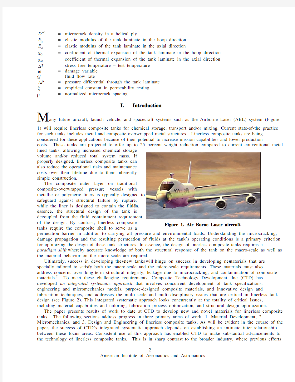
1) will require linerless composite tanks for chemical storage, transport and/or mixing. Current state-of-the practice for such tanks includes metal and composite-overwrapped metal structures. Linerless composite tanks are being considered for these applications because of their potential to increase mission capabilities and lower production costs. These tanks are projected to offer up to 25 percent weight reduction compared to current conventional metal lined tanks, allowing increased chemical storage volume and/or reduced total system mass. If properly designed, linerless composite tanks can also reduce the operational risks and maintenance costs over their lifetime due to their inherently simple construction. The composite outer layer on traditional composite-overwrapped pressure vessels with metallic or polymeric liners is typically designed to safeguard against structural failure by rupture, while the liner is designed to contain the fluids.1 In essence, the structural design of the tank is decoupled from the fluid containment requirement of the design. By contrast, linerless composite Figure 1. Air Borne Laser aircraft tanks require the composite shell to serve as a permeation barrier in addition to carrying all pressure and environmental loads. Understanding the microcracking, damage propagation and the resulting permeation of fluids at the tank’s operating conditions is a primary criterion for optimizing the design of these tank structures. In essence, the design of linerless composite tanks requires a paradigm shift whereby accurate knowledge of both the structural response of the tank on the macro-scale as well as the material behavior on the micro-scale are required. Ultimately, success in developing these new tanks will hinge on success in developing new materials that are specially tailored to satisfy both the macro-scale and the micro-scale requirements. These materials must also address concerns over long-term structural integrity, leakage due to microcracking, and contamination of composite materials.2 To meet these challenging requirements, Composite Technology Development, Inc (CTD) has developed an integrated systematic approach that involves concurrent development of tank specifications, engineering and micromechanics models, purpose-designed composite materials, and innovative design and fabrication techniques, and addresses the multi-scale and multi-disciplinary issues that are critical in linerless tank design (see Figure 2). This integrated systematic approach looks concurrently at the totality of critical issues, including material capabilities and tailoring, fabrication process optimization, and structural design optimization. The paper presents results of work to date at CTD to develop new and novel materials for linerless composite tanks. The following sections address progress in three primary areas of work: 1. Material Development, 2. Micromechanics, and 3. Design and Engineering of linerless composite tanks. As will be evident in the course of the paper, the success of CTD’s integrated systematic approach depends on establishing an intimate inter-relationship between these focus areas. Consistent use of this approach has enabled CTD to make substantial advancements to the technology of linerless composite tanks. This is in sharp contrast to the broader industry, where previous efforts 2 American Institute of Aeronautics and Astronautics
M
any future aircraft, launch vehicle, and spacecraft systems such as the Airborne Laser (ABL) system (Figure
Figure 2. The integrated systematic approach provides an inter-disciplinary and multi-scale methodology in developing lightweight linerless composite tanks. to develop linerless composite tanks have met with limited success due to a lack of focus across all relevant areas and size scales.
II. Material Development
A. Development of Novel Matrix Materials CTD’s material development effort towards linerless composite tanks has focused on toughened epoxy matrices with improved resistance to microcrack formation. Several new approaches have been investigated in novel material formulation, including the use of rubbers and commercially available block copolymer impact modifiers. During the material development effort, epoxy resin mixtures have been selected to achieve an optimized balance between resin cost, performance, and processing. In addition, various curing agents have been evaluated to provide improved potlife and shelf-life with a room temperature cure. Longer pot-life times are anticipated to enable fabrication of largerscale composite structures and provide for a higher level of end-user acceptability. CTD has also used vapor grown carbon fiber (VGCF) nano-reinforcements in the matrix for improved modulus and higher inter-laminar shear strength at the ply interfaces. Experimental results indicate that the microcrack resistance of cross-ply laminates made with VGCF reinforced epoxy matrix is significantly higher than that of commercial-off-the-shelf (COTS) materials like Cytec’s 977-2 and 977-3 used traditionally in composite tanks. B. Microcracking Performance Assessment through Uniaxial Tests ‘Microcracking fracture toughness’ (MFT) has been identified as an effective analytical tool to screen and down-select the materials for linerless composite tanks.3-6 The instant of formation of the microcrack is predicted when the total energy released by the formation of that microcrack reaches the critical energy release rate for microcracking, Gmc, or the MFT. Evaluating a material’s MFT involves uni-axial tensile tests of cross-ply laminates [0/90n]s where n is the number of plies in the 90o plies sandwiched between the 0o plies (see Figure 3). Laminates for MFT tests were manufactured by CTD using a wet lay-up procedure and a high-temperature hydraulic press for compaction and cure resulting in a fiber volume fraction of Vf = 60%. Test specimens (13 mm wide by 200 mm long) are cut from the laminate using diamond saw and edges polished by a 3 micron diamond slurry. Typical ply thickness of a specimen is 0.15 mm. During the MFT test, the specimen is subjected to tensile strain, which is increased in increments. The edge of the specimen is inspected at each strain increment using a 10x hand-held digital microscope connected to a personal.
0o plies
90o plies
Figure 3. The polished edge of a MFT test specimen of [0/90]s layup.
3 American Institute of Aeronautics and Astronautics
The number of microcracks in the central ply is counted on the computer monitor while the microscope traverses the length of the specimen edge. The microcrack count is performed for each edge of the specimen and the average microcrack density (number of microcracks divided by the specimen edge length) is reported for each strain level. The procedure is repeated until the tensile failure of the specimen is complete. Determining the microcrack density of the specimens in situ in the test frame avoids dismantling the specimens from the testing machine and remounting them under an optical microscope for counting of microcracks. More importantly, microcracks are easily identified and more accurately counted when the specimen is strained, since previous researchers have reported closure of microcracks in the absence of load. Figure 4 shows the 1.2 microcrack density as a IM7 977-3 T-700 977-2 function of the applied T-700 CTD-12XQ strain for several different 1 T-700 CTD-15XQ composite materials tested T-700 CTD-525 at room temperature. The T-700 CTD-7.1 0.8 laminate configuration for T-700 CTD-DP5.1 T-700 CTD-DP5.1+VGCF these specimens was [02,904]s with a ply 0.6 thickness of 0.15mm and a fiber volume fraction of 60%. The higher the 0.4 microcrack fracture toughness of a material, the lower the microcrack 0.2 density at a given strain level, which in turn is 0 likely to promote less 0 0.2 0.4 0.6 0.8 1 1.2 1.4 1.6 1.8 permeation of fluids Strain (%) through the tank wall. Figure 4. Growth of microcracks vs. strain in a cross-ply laminate From these test results, for several materials tested by CTD at room temperature. several of CTD’s new 1.6 matrix materials (e.g., Delamination CTD-7.1 and CTD-DP5.1) 1.4 show very high First Failure (Microcrack or Delamination) microcrack fracture 1.2 toughness as compared to the industry standard 1 Cytec 977-2 and 977-03 resins. 0.8 The strains to initiate microcracking and 0.6 delamination are important design 0.4 parameters for linerless composite tanks. Figure 5 0.2 shows these two types of failure strains in cross-ply 0 laminates for several T700 + Cytec IM7 + Cytec T700 + CTDT700 + CTDT700 + CTD T700 + CTDmaterials tested by CTD at 977-2 977-3 525 DP5.1 DP5.1 w/VGCF 7.1 Interface room temperature. Results Figure 5. Strain to initiate microcracking and delamination for several shown in this plot are materials tested at room temperature. averaged over five different specimens. It is interesting that no microcracks are detected in specimens made with CTD DP5.1 and CTD 7.1. The first mode of failure was delamination in these materials that occurred above 1% strain, a target strain level to achieve the design optimization goals for linerless composite tanks.6 Addition of nano-reinforcements in the form of vapor grown carbon fibers (VGCFs) in the ply interface increased the delamination strain to 1.5%. This matrix-driven failure
Strain(%)
Microcrack Density (1/mm)
4 American Institute of Aeronautics and Astronautics
mode of the material is encouragingly close to the ultimate fiber-failure strain of 1.7%. This is a significant performance improvement in comparison to Cytec’s 977-2 and 977-3 materials that show microcrack formation at strain levels close to 0.5%. C. Permeability Performance Assessment through Sub-Component Biaxial Pressure Tests The MFT tests described above are designed to screen the matrix materials based on their performance against microcrack formation under uniaxial load. In addition to these coupon-level tests, a sub-component-level test is required to characterize permeability performance of composite laminates subjected to biaxial stress under pressure loading. This test characterizes laminates fabricated by a method that represents the actual fabrication of the composite tanks. Hence, the results of the tests should directly relate to full-scale tank performance. A schematic of the test setup being developed by CTD is shown in Figure 6.7 The test article consists of a filamentwound, linerless composite pipe with adhesively bonded metallic end sleeves (Figure 7(a)) and flanged end caps enclosed in a vacuum chamber that suspends the cylinder by one end (Figure 7(b)). The unsupported end of the test cylinder is free to expand, thus achieving the desired 2-to-1 ratio in hoop-to-axial stress, which is typical of cylindrical Figure 6. Schematic design of the permeability test setup. pressure vessels. A vacuum pump and helium leak detector are attached to the vacuum chamber to measure the rate of helium leakage as a function of pressure and temperature. The objective of the test is to measure the helium permeation as well as the hoop and axial strains in the pipe as a function of the applied pressure and the progressive damage due to microcracking in the composite plies. The test results will be used to validate the analytical predictions of permeability and ultimate strength based on micromechanics as explained in the following section.
(a)
(b)
Figure 7. Test fixture for pressure testing of filament wound pipes.
III. Micromechanics
In composites, failure is usually a progressive process. Often, a wide margin can be found between the first incident of micro-scale failure and the ultimate failure. Indeed, the accumulation of damage through microcracking is such a progressive failure process, and understanding this failure progression and the effect of microcracking on permeability are keys to the design optimization of linerless tanks. As depicted in Figure 8, permeation pathways can
Figure 8. Idealization of leakage path through microcracks in adjacent plies of a composite laminate.
5 American Institute of Aeronautics and Astronautics
develop through microcracks in adjacent layers of a multi-layer, filament-wound tank. The goal of the micromechanics-based analysis is to establish analytical models predict the nucleation and growth of microcracks and relate the microcrack density to global stiffness reduction and ultimately to leakage. A. Microcracking and Permeation The successful design optimization of a linerless tank requires an understanding of the degree of microcracking in the individual plies and how that affects the permeation or flow of fluid through the laminate.8 The laminate in a filament-wound composite tank typically consists of interspersed layers of hoop and helical plies. Therefore, the cylindrical section of the tank shell can be modeled as a sequence of mixed ply laminates [90/( ±θ )]s stacked in series; angles being measured with respect to the cylinder axis. As the tank is pressurized, equilibrium dictates that the ratio σ θ /σ a = 2 remains constant in the cylinder section, where σ θ is the hoop stress and σ a is the axial stress. Since the helical plies are subjected to a higher transverse stress magnitude of σ θ = 2σ a , they will experience microcracking before the hoop plies. The expected evolution of microcrack density in the composite laminate is illustrated schematically in Figure 9(a). Because of the biaxial stress state, analytical estimation of the growth of microcracks needs to be performed ith the constraint of σθ = 2σa (Figure 9(b)).6 As long as microcracking does not occur in the hoop plies, they can prevent the flow of fluids through the laminate, thereby keeping the permeability of the laminate negligible. However, as (a) (b) the pressure is further increased, Figure 9: Growth of (a) microcracks and (b) permeability in a a critical value of internal composite laminate under biaxial load. (and the pressure pc corresponding axial stress, σ a ) is reached that causes microcracking in the hoop plies, thereby providing an interconnected pathway for the fluid to permeate through the entire laminate. The following section illustrates how the critical pressure pc can be estimated using the MFT of the matrix material. B. Prediction of Microcrack Initiation under Biaxial Load Containment and ‘management’ of microcrack-induced damage in the linerless composite tank requires the ability to predict microcrack initiation in a multi-ply laminate subjected to biaxial loading, taking full account of both anisotropy and thermally induced stresses. Figure 10 shows the cylindrical section of a filament-wound tank subjected to a biaxial stress. The tank is assumed to have closed ends, thereby producing an axial stress σ a = pR / 2t and a circumferential stress σ θ = pR / t , where p is the internal pressure, R is the tank radius and t = 2(t1 + t 2 ) is the total Figure 10. Biaxial stresses acting on (a) a tank cylindrical section thickness of the laminate. Tracking and (b) an idealized geometry. the damage evolution in the laminate 6 American Institute of Aeronautics and Astronautics
due to internal pressurization will require solving two simultaneous equations for the two directions – axial and circumferential. The damage evolution laws for the biaxial loading conditions are derived in Appendix A. These equations require an analytical understanding of the degradation of the effective stiffness and coefficient of thermal expansion of the laminate in the two directions due to the evolving damage in both the hoop and helical plies. If the tank is fabricated with a room-temperature-cure resin system, like CTD 7.1, and operated at roomtemperature, the differential between the stress free temperature during tank cure and the tank test temperature can be neglected, i.e. ?T ≈ 0 . Substituting σ a = pR / 2t and σ θ = pR / t in equation A2 (see Appendix A), the pressure p at which microcracks are initiated in the hoop plies is derived as:
p=
2t R(1 + 2ka )
(2G
mc D
90
)/
Ea D
( )
90
1
?
1 Ea
(1)
and ρ = a/t1 is the normalized microcrack spacing in the hoop (90o) plies. The parameter ka is a laminate constant that has been defined in Appendix A. Ea is the effective modulus of the laminate in the axial direction that depends on the microcrack density D90 in the hoop plies. Assuming θ ≈ 0 for low-angle helical plies typical of a filamentwound tank, the functional dependence of Ea on the microcrack density D90 can be derived as:9
where, Gmc is the microcrack fracture toughness of the composite material, D 90 = 1 /(2 ρt1) is the microcrack density
1 1 4t12C 3 E2 2 = + χ (D 90 )D 90 2 Ea (D) E a tEa
(2)
where the parameter C 3 is a material constant that has been defined elsewhere in reference to the theoretical framework of microcrack fracture toughness.6 Combining eqs. (1) and (2), the engineering estimate of the critical pressure pc at which microcracks are initiated in the hoop plies under biaxial load is derived as:
pc =
2t R(1 + 2k a )
2t12C 3 E2 2 χ (D)
G mc tEa 2
(3)
The material’s MFT (Gmc) measured from uniaxial experiments can therefore be used in eq. (3) to predict the critical pressure where the tank starts to leak. C. Dependence of Permeability on Damage Evolution Initiation of leakage is not catastrophic in composite tanks as long as it is contained within engineering design limits. Therefore, in some cases it may be necessary to predict the leakage or permeability of the tank laminate beyond the critical pressure where the permeability becomes non-zero. The concept of effective conductance can be used to estimate the leak rate of the fluid through the composite laminate.10 Effective conductance of the laminate is directly related to the volumetric flow rate of the fluid leaking through a composite laminate and is defined by:
C=
Q ?P
(4)
where Q is the flow rate and ?P is the pressure differential across the laminate. If C1, C2, …Cn define the individual conductance of each ply junction, the effective conductance of the composite laminate can be defined as:10
C=
n k=1
1 Ck
?1
(5)
Now, if the adjacent plies of the tank laminate are microcracked, the conductance of each ply junction can be hypothesized to be: 7 American Institute of Aeronautics and Astronautics
Ck = ξ
ω k ω k +1? k ? k +1 cos θ k
(6)
where ξ is a material constant to be determined from experiments, ωk is a parameter that defines the damage, ?k is the mean-opening displacement of the microcracks in the kth ply and θ k is the angle of the helical ply, measured with respect to the tank axis. Combining Equations (4)-(6), the effective mass flow rate through a microcracked laminate is given by:
Q =ξ
n k=1
cos θ k ?P ω k ω k +1? k ? k +1
(7)
The average microcrack opening displacement (MCOD), ? depends on the degradation in effective stiffness of the composite ply and can be calculated from the reduction in elastic modulus of the laminate. Computations show that MCOD increases with the crack spacing and decreases with microcrack density. 11Analytical expressions for the MCOD in the 90o plies of a [(±θ)/90]s laminate as a function of microcrack density is given in Appendix B. Analytical estimation of ? in each ply and its subsequent incorporation in eqn. (7) completes the theoretical formulation relating the flow rate Q of a multi-ply composite tank laminate as a function of applied internal pressure, P. The formulation can be implemented in the finite element analysis of a linerless composite tank to predict the permeability of the entire tank.
IV. Tank Design and Engineering
D. Isostrain Design to Minimize Microcracking in Domes Traditionally the domes in composite pressure vessels have been designed based on netting analysis.1 For filament-wound tanks such optimized dome designs are also referred to as geodesic isotensoid designs. The word geodesic refers to a curvature that provides stability against fiber slippage during winding and the word isotensoid refers to a structurally optimized dome contour that ensures uniform tension along the fiber direction on any point of the dome. Essentially, the structural design of an isotensoid dome neglects the failure mode of the composite transverse to the fiber direction. The philosophy of isotensoid domes is adequate for a lined pressure vessel where the liner is responsible for fluid containment and therefore, matrix microcracking is not an influencing factor. The structural design of a dome in a linerless composite tank, on the other hand, must account for the failure characteristics of the composite transverse to the fiber. An isostrain dome profile is an alternative design, which assures that the fibers are placed Dome contours along the directions of the principal stresses in 0.7 each layer and that the principal strains are 0.6 constant at any point of the dome. As matrix microcracking has been shown to be a strain0.5 dependent failure phenomenon, it follows that an isostrain dome design will provide more uniform 0.4 microcracking performance, and hence, a more efficient design to inhibit microcracking and 0.3 permeation than an isotensoid design. The fundamental assumptions and topology of an 0.2 isostrain dome profile are discussed in Appendix Isotensoid (k = 0) 0.1 D and a comparison of isostrain and isotensoid Isostrain (k = 0.1) dome profiles is shown in Figure 11. In this 0 derivation it is shown that the ratio of the stress in 0 0.2 0.4 0.6 0.8 1 the fiber direction to that in the transverse r/Rc direction at any point on the dome is a constant, k, defined in eqn. (9). Note that the isotensoid Figure 11: Comparison of an isotensoid and an design is essentially a degenerate case of the isostrain dome profile 8 American Institute of Aeronautics and Astronautics
z/Rc
isostrain design in which k is zero.
k = σ 2 /σ 1
(8)
u maximum strength. Assuming that the strength of a uni-directional ply is defined by σ 1u and σ 2 in the two directions, parallel and perpendicular to the fiber, a material constant, k1, which relates these orthotropic failure stresses can be defined: u u k1 = σ 2 / σ 1
If the material is assumed to be linearly elastic, as most carbon fiber reinforced thermosets are, the above relation will hold true when the shell is pressurized until one of the stresses σ 1 or σ 2 attains the maximum value or the
(9)
Figure 12 shows the different laminate response when the dome is pressurized for different values of the operating stress ratio, k, relative to the material strength ratio, k1. An assumed failure envelope of the unidirectional ply is defined u by the rectangle, σ 1 = σ 1u ,σ 2 = σ 2 . The three lines consider three hypothetical cases depending on the material characteristics. Line 1 characterizes the case when k > k1 and the matrix fails in the tank dome before the fiber ruptures. Line 3 represents the case when k < k1 , when the fiber fails in the dome before the matrix. The ideal case is shown in Line 2 where k = k1 and the matrix and the fiber fail simultaneously.
2 u 2 1
k>k1
2 3
k=k1
k
Figure 12: Failure envelope and types of loading for a composite shell.
E. Finite Element Analysis of Filament-Wound Tanks In order to accurately account for the multiple aspects of material performance (i.e., orthotropic strength, changing stiffness, permeability, etc.) the structural design of the linerless composite tank must refined using Finite Element Analysis (FEA). A proprietary in-house program has been developed by CTD to generate the finite element model of the composite tank given a user-defined envelope of the tank geometry, the design parameters, and the tank’s laminate sequence. The program creates an input file to be interpreted by a commercial finite element program, like ABAQUS. An axisymmetric model for half of a prototype 10” ID x 18” long tank created by this program is shown in Figure 13. The FEA model accounts for: 1. Spatially varying material properties in the tank structure ? The orthotropic properties of the composite layers in the filament wound cylindrical shell ? The orthotropic properties and thickness of each element in the dome ? The polar buildups during wind ? The hoop stagger at the transition region
2. Geodesic isostrain (or isotensoid) dome profile. 3. The non-linear variation of material properties (elastic moduli, CTEs) with strain level, degree of
microcracking, temperature etc.
4. Interface between the polar bosses and the composite shell overwrap 5. Load sequence that can combine pressure and thermal loads.
9 American Institute of Aeronautics and Astronautics
The boundary conditions applied to the model consist of symmetry conditions at the cut surface in the middle of the cylinder, a uniform pressure of p on Polar Boss the inside surface of the tank as shown in Figure 13, and a displacement boundary condition (uy = 0) is imposed on the center of the tank (y = 0) to restrain it Polar against rigid body motion in the axial buildups direction. The interface between the composite shell and the polar boss is modeled using ABAQUS’s “cohesive elements” (Figure 14). These elements are effective in modeling the behavior of adhesive joints, interfaces in composites, Staggered Hoop and other situations where the integrity terminations and strength of interfaces may be of interest.12 The constitutive response of these elements is assumed to be based on a traction-separation description of the interface. The behavior of the interface Internal Pressure prior to initiation of damage is described as linear elastic. Once the damage is initiated, the stiffness degrades under tensile and/or shear loading, but is unaffected by pure compression. A simple linear damage evolution law is used to describe the rate at which the material stiffness of the interface is degraded once the pre-defined damage initiation criterion is reached. Inside Radius The finite element analysis is performed using a non-linear geometry option with the internal pressure applied incrementally in time steps up to the design pressure. Figure 15 plots the longitudinal and transverse strain of each ply along the meridional distance (distance measured along the tank meridian / dome profile) starting from the center of the tank. Figure 15(a) also shows that there are no stress peaks in the dome regions that would cause a dome rupture if the pressure was increased beyond its design pressure. However Figure 15(b) shows that the transverse strain is abnormally high in the hoop plies around the cylinder-todome transition area. This is likely to cause microcracking in the hoop plies leading to leakage in the cylinder-todome transition area. This is precisely the level of insight that is necessary to refine the laminate and shell design in order to maximize efficiency.
1/2 x Cylinder Length
Symmetric boundary conditions at mid -cylinder
Figure 13: FEA model of a filament wound composite tank
Cohesive elements
Figure 14: ABAQUS's cohesive elements are used to model the interface between polar boss and composite overwrap.
10 American Institute of Aeronautics and Astronautics
(a)
(b)
Figure 15: (a) Longitudinal and (b) Transverse strain in composite plies of the prototype tank at its operating pressure derived from FEA analysis
F. Fabrication of Prototype Linerless Composite Tanks Prototype linerless composite tanks, 10-inch diameter x 18-inch, were fabricated using a 5-axis filament winding machine at the Air Force Research Laboratory, Kirtland. The mandrel was fabricated in two halves using a washable eutectic salt called AquaPour? made by Advanced Ceramics Research, Inc., Tucson, Arizona. Four tows of Toray T700-SC 12K carbon fiber tows and a toughened epoxy CTD 7.1 resin were used during the fabrication process (Figure 16). The tank laminate layup consisted of interspersed hoop and helical layers, with the hoop layers providing compaction and consolidation of the previous helical layer. The winding tension was varied to avoid fiber microbuckling. Finished tanks were oven cured, after which the mandrels were washed out using water leaving the finished linerless composite tanks. At the time of the present report, CTD was preparing to perform pressure testing on these prototype tanks.
Figure 16: Different stages in the fabrication of a prototype linerless composite tank
Summary
This paper describes a program currently underway at Composite Technology Development, Inc. to dramatically improve the design and capabilities of lightweight linerless composite tanks. The program integrates material development and characterization, micromechanics-based analyses, and structural design and fabrication of prototype tanks. This integrated systematic approach, addresses the multi-scale and multi-disciplinary issues that are critical to linerless composite tank design by looking concurrently at material requirements capabilities and tailoring, refinement of fabrication process, and structural design optimization. Unlike traditional composite over-wrapped pressure vessels, linerless composite tanks depend on the composite shell itself to serve as a permeation barrier in 11 American Institute of Aeronautics and Astronautics
addition to carrying all pressure and environmental loads. Designing these tanks requires accurate knowledge of the structural response of the tank on the macro-scale as well as the material behavior on the micro-scale. It is clear that limiting and managing the development of microcracks and microcrack-induced permeability in the composite shell dictates that new materials must be tailored specially for this purpose. To that end, this paper describes how micromechanics-based analysis is used to: 1) define critical material-performance parameters that drive the development of new toughened matrices, and 2) predict microcrack formation and permeability in composite laminates under biaxial load. Test data are presented that show new toughened resin systems exhibit dramatic improvements in microcrack fracture toughness, and strain-to-failure response as compared to industrystandard epoxy systems. The concept of isostrain design is introduced for use in optimization of dome structural design. Issues related to finite element analysis of these tanks are discussed, and a proprietary computer program to generate the finite element model of a composite tank given a user-defined envelope of the tank geometry, the design parameters, and the tank’s laminate sequence, is described. Finally, the paper presents progress to date in designing and fabricating linerless composite tanks using a newly developed, microcrack-resistant resin system.
Appendix A. Damage Evolution in a Tank Laminate Under Biaxial Load
The cylindrical section of a filament-wound composite tank consists of interspersed layers of hoop and helical plies subjected to a biaxial stress state. Consequently, the building block for damage (microcrack) analysis of the laminate consists of a [90/(±θ)]s laminate for circumferential load (σa) and a [(±θ)/90]s laminate for the axial load (see Figure 17). For the former, the damage evolution law in the helical ( ± θ ) ply of the [90/(±θ)]s laminate is given by:13
σ θ + kθσ a =
2Gmc D ±θ 1 1 ? ±θ Eθ (D ) Eθ
?
αθ (D ±θ ) ? αθ
1 1 ? ±θ Eθ (D ) Eθ
?T
(A1)
Similarly, the damage evolution law in the 90o plies of the building block defined by [(±θ)/90]s laminate is given by:
σ a + k aσ θ =
2Gmc D 90 1 1 ? 90 Ea E a (D )
?
α a (D 90 ) ? α a
1 1 ? 90 Ea E a (D )
?T
(A2)
where, Gmc is the microcrack fracture toughness of the composite material, D 90 and D ±θ are the damage variables for the hoop (90o) and helical (±θ) plies, Eθ and Ea are the moduli, αθ and αθ are the effective coefficients of thermal expansion (CTE) of the tank laminate along the circumferential and axial direction, ?T is the difference between the stress-free temperature of the laminate (cure temperature) and the test temperature and kθ an ka are laminate constants defined as:13
Eθ ±θ Ea 90 ν 21 ? νθa ν 21 ? ν aθ E E kθ = a ; ka = θ ±θ 90 1 ? ν θa ν 21 1 ? ν aθ ν 21
(A3)
The transcendental set of equations (A1) and (A2) together define a complete description of damage evolution in the tank laminate with the help of microcrack fracture toughness and an apriori knowledge of the change in effective modulus and effective CTE of the laminate in both the circumferential and axial directions.
12 American Institute of Aeronautics and Astronautics
Figure 17: Two complimentary building blocks for damage analysis of a filament wound tank.
Appendix B. Modulus Reduction Due to Microcracks in the Hoop (90o) Plies
The expression of the effective elastic modulus E of the [(±θ)/90]s laminate as a function of microcrack density in the 90o plies, normalized with respect to the modulus E0 of the virgin laminate is given by:14,15
E 1 = E0 1 + aD 90 χ (ρ )
(B1)
where:
a=
0 E 2 t1 1 ? ν 12ν xy E θ t 2 1 ? ν 12ν 21 x
1 +ν θ xy
θ S xy t1 + S12 t 2
S θ t1 + S11t 2 yy
(B2)
χ (ρ) = 2αβ α 2 + β 2
In (B1), (B2) and (B3) spacing,
(
cos 2 )βcosh 2αρ ? α sin βρ sinh 2αρ + 2βρ
(B3)
θ 0 Sij represents the compliance terms for the ±θ ply and ν xy and S ij represent the Poisson’s ratio and the
D 90 is the microcrack density in the hoop (90o) plies, ρ = 1 / (2 D 90t1 ) is the normalized crack
compliance terms respectively for the virgin [(±θ)/90]s laminate. Figure 18 plots the reduction in effective modulus of a [(±θ)/90]s laminate defined by eqn B1 for three different values of θ. The ply thickness used in computation is 0.15 mm and the values of θ selected are typical of a composite tank fabricated by CTD.
13 American Institute of Aeronautics and Astronautics
1
θ = 10 θ = 15 θ = 20
0.96
E/E0
0.92
0.88
0.84 0 0.5 1 1.5
90
2
2.5
3
Microcrack Density D
(1/mm)
Figure 18: Reduction of the effective modulus of a [(±θ)/90]s laminate with increase in microcrack density D90 in the 90o plies The average microcrack opening displacement (MCOD) in the 90o ply can be computed from:14
? = t1ε χ (ρ )
2 E θ t 2 1 ? ν 12ν 21 x
E2t1
0 1 ? ν 12ν xy
1+
S θ t2 xx
S 22 t1
?
(S θ t + S t ) S θ t (S θ t + S t )
2 xy 1 12 2 xx 1 yy 1 11 2
(B4)
Appendix C. Modulus Reduction Due to Microcracks in the Helical (±θ) Plies. θ
Assuming that during the initial stages of loading, microcrack formation in the angle-ply (±θ) laminate is dispersed and random, the reduction in ply elastic parameters due to dispersed microcracks can be modeled using mean field theories of elasticity. The formation of microcracks in the angle-ply (±θ) layer can be modeled as formation of multiple slits in an orthotropic 2-D medium, in which all slits are divided into two systems. Each of these two-slit systems consists of N/2 aligned microcracks of equal length 2a. Microcracks in these two systems subtend angles + θ and ? θ , respectively. The elastic parameters E11 and E22 of the ply can be computed by solving the following linear equations:16
(1 ? 2πωB11 )
? 2πωB11
1 1 1 ? 2πωB12 = 0 E11 E 22 E11
(C1)
1 1 1 + ( ? 2πωB22 ) 1 = 0 E11 E 22 E 22
where,
B11 = 1 ? 2 cos 2 θ + 2 cos 4 θ ? cos 6 θ B12 = cos 2 θ ? 2 cos 4 θ + cos 6 θ B21 = cos θ ? cos θ ? sin θ cos θ
2 8 6 2
(C2)
B22 = cos 8 θ + sin 6 θ cos 2 θ
and ω = Na 2 is the Budiansky and O’Connell microcrack density, defined in terms of the microcrack half-length (a) and the number of microcracks per unit area, N.17 14 American Institute of Aeronautics and Astronautics
Given the stiffness reduction for the angle-ply (±θ) layer as a function of the damage density, the effective stiffness of the [90/(±θ)]s laminate can be calculated from simple laminate analysis. Figure 19 plots the reduction in effective modulus of the [90/(±θ)]s laminate as a function of the damage parameter, ω . Results are computed for three cases, θ =10o, 15° and 20o, that are typical of helical plies in a filament wound tank.
1
0.98
θ = 10 θ = 15 θ = 20
E/E0
0.96
0.94
0.92 0 0.05 0.1 0.15 0.2 0.25
Damage Density in ±θ plies (ω )
Figure 19: Reduction of the effective modulus of a [90/(±θ)]s laminate with increase in microcrack density ω in the ±θ plies
Appendix D. Isostrain Dome Profile
Consider a filament-wound tank dome as shown in Figure 20. The dome profile is characterized by the radius, r and the dome height, z. The stress resultants in the composite shell when the tank dome is under internal pressure, p can be written as:18
Nφ = Nθ =
pR2 = A11εφ + A12εθ 2 pR R 2 ? 2 = A12εφ + A22εθ 2 R1
(D1)
where, N φ ,Nθ are the meridional and circumferential stress resultants, εφ ,εθ are the meridional and circumferential strains and R1, R2 are the principal radii of curvature of the dome as shown in Figure 20. The parameters Aij, i=1,2 are the in-plane laminate stiffness resultants, which can be determined from composite laminate theory at each point in the dome and depend on the laminate architecture at that point.
Figure 20: Geometry of filament wound dome profile. 15 American Institute of Aeronautics and Astronautics
The equations relating the shell strains εφ ,εθ to the strains ε1,ε 2 , along and across the fibers, and to the in plane shear strain ε12 are:
ε1 = εφ cos 2 β + εθ sin 2 β ε 2 = εφ sin 2 β + εθ cos 2 β ε12 = (ε1 ? ε 2 )sin 2β
where, β is the angle of the fiber orientation with respect to the meridional axis and changes continuously along the dome in a helical wind pattern (see Figure 20). If the dome is designed such that the fibers are placed along the directions of the principal stresses in each layer, the shear stress and the shear strain in each layer can be assumed to be zero. Therefore, (D2)
ε12 = 0,ε1 = ε 2 = εφ = εθ = ε
(D3)
A composite shell that can maintain the above relationship can be called an isostrain dome, such that the strain at each point on the dome, both along and across the fiber direction, is a constant, ε. The constitutive equations for an orthotropic material are given as:
σ 1 = E1(1 + ν 21)ε σ 2 = E2 (1 + ν 12 )ε
where,
(D4)
Ei =
1 ? ν12ν 21
Ei
, i = 1,2
Solving eq. (D1) with eq. (D3) and substituting the result in eq. (D4), the principal stresses in the shell are obtained as:
σ1 = σ2 =
h E1(1 + ν 21) + E2 (1 + ν 12 )
[
E1(1 + ν 21 ) N φ + Nθ E2 (1 + ν 12 ) N φ + Nθ
(
)
h E1(1 + ν 21 ) + E2 (1 + ν12 )
[
(
)
] ]
(D5)
It follows directly from eq. (D5) that the ratio of the stress in the fiber direction and that in the direction perpendicular to the fibers at any point on the isostrain dome is given by:
σ 2 E2 (1 + ν 12 ) = =k σ 1 E1(1 + ν 21)
(D6)
The optimized profile of an isostrain dome can be determined from eqs. (D1), (D3) and radius of curvature of the shell, resulting in the following differential equation:
z '1 + (z ' )
[
rz"
2
]
= 2?
1 ? (1 ? k ) cos 2 β
k + (1 ? k ) cos 2 β
(D7)
The shape of the dome profile is determined by integrating equation (D7):
z (r ) =
Rc r
1
k + (1 ? k ) cos β k + (1 ? k ) cos 2 β 0 r cos β
2
2 Rc cos β 0 2
2
dr ?1
(D8)
The variation of the fiber orientation angle, β is determined from: 16 American Institute of Aeronautics and Astronautics
cos k β 0 1 ? (1 ? k) cos 2 β 0 r = (1? k) / 2 Rc cos k β 1 ? (1 ? k ) cos 2 β
In eqs. (D7) and (D8) r=Rc and β = β 0 when z=0.
[ [
] ]
(1?k) / 2
(D9)
Acknowledgments
This material is based upon work supported by the United States Air Force under Contract No. HQ0006-04-C-7069, HQ0006-04-C-7070, FA9453-03-C-0211 and FA9453-03-C-0213. Any opinions, findings and conclusions or recommendations expressed in this material are those of the author(s) and do not necessarily reflect the views of the United States Air Force.
References
1. 2. 3.
4. 5. 6. 7. 8.
9. 10. 11.
12. 13. 14. 15. 16. 17. 18.
Peters, S.T., Humphrey, W.D. and Foral, R.F., Filament Winding Composite Structure Fabrication, 2nd ed., SAMPE publication,1987. Robinson, M. J., “Composite Cryogenic Tank Development”, 35th Structures, Structural Dynamics, and Materials Conference and Adaptive Structures Forum, 1994. Mallick, K., Tupper, M. L., Arritt, B. J. and Paul C., “Thermo-micromechanics of Microcracking in a Composite Cryogenic Pressure Vessel”, 44th AIAA/ASME/ASCE/AHS/ASC Structures, Structural Dynamics & Materials Conference, Norfolk, Virginia, 7-10 April, 2003. Nairn, John A., “Matrix Microcracking in Composites,” Polymer Matrix Composites, Elsevier Science, R. Talreja and J-A, Manson eds., Chapter 13, 2001. Nairn, John A., “The Strain Energy Release Rate of Composite Microcracking: A Variational Approach”, Journal of Composite Materials., Vol. 23, pp 1106-1129, 1989. Mallick, K. et al., “Ultralight Linerless Composite Tanks for In-Space Applications,” presented at the AIAA Space 2004 Conference, San Diego, Sept. 27-30, 2004. Roth, A. Vacuum Technology, North Holland Publishing, New York, 1976. Bechel, V. T. and Kim, R. Y., “Through Laminate Damage in Cryogenically Cycled Polymer Composites”, 45th AIAA/ASME/ASCE/AHS/ASC Structures, Structural Dynamics & Materials Conference, Palm Springs, California, 19-22 April 2004. Nairn, J. A. and Hu, S., “The Formation and Effect of Outer-Ply Microcracks in Cross-Ply Laminates: A Variational Approach”, Engineering Fracture Mechanics, Vol. 41, 203-221, 1992 Roy, S. and Benjamin, M., “Modeling of Permeation and Damage in Graphite/Epoxy Laminates for Cryogenic Fuel Storage”, Composites Science and Technology, Vol. 64, 2051-2065, 2004. Noh., J., et al., “Numerical Modeling of Cryogen Leakage through Composite Laminates,” AIAA paper 2004-1862, 45th AIAA/ASME/ASCE/AHS/ASC Structures, Structural Dynamics & Materials Conference, Palm Springs, California, 19 - 22 April 2004. ABAQUS Analysis User’s Manual, v. 6.5-1, 2004. McCartney, L. N., “Predicting transverse crack formation in cross- ply laminates resulting from micro-cracking”, Composite Science and Technology, Vol. 58, pp. 1069-81, 1998. R. Joffe and J. Varna, “Analytical Modeling of Stiffness Reduction in Symmetric and Balanced Laminates due to Cracks in 90o Layers”, Composites Science and Technology, 1999, Vol. 59, pp. 1641-1652. R. Joffe and J. Varna, “Damage Evolution Modeling in Multidirectional Laminates and the Resulting Nonlinear Response”, Proceedings of ICCM-12, 5-9 July, 1999, Paris, France. Sumarac, D., Krajcinovic, D. and Mallick, K.,“Elastic Parameters of Brittle, Elastic Solids Containing Slits – Mean Field Theory,” International Journal of Damage Mechanics, Vol. 1, pp. 320-346, 1992. Budiansky, B. and Connell, R. J., “Elastic Moduli of a Cracked Solid,” International Journal of Solids and Structures, Vol. 12, 81-97, 1976. Bukanov, V. A. and Protasov, V. D., “Composite Pressure Vessels,” Chapter 9, in Handbook of Composites, Vol. 2 Structure and Design, Elsevier Science Publishers, 1989.
17 American Institute of Aeronautics and Astronautics
航空航天复合材料技术发展现状
航空航天复合材料技术发展现状 2008-11-25 中国复合材料在线[收藏该文章] 材料的水平决定着一个领域乃至一个国家的科技发展的整体水平;航空、航天、空天三大领域都 对材料提出了极高的要求;材料科技制约着宇航事业的发展。 固体火箭发动机以其结构简单,机动、可靠、易于维护等一系列优点,广泛应用于武器系统及航 天领域。而先进复合材料的应用情况是衡量固体火箭发动机总体水平的重要指标之 一。在固体发动机研制及生产中尽量使用高性能复合材料已成为世界各国的重要发展目标, 目前已拓展到液体动力领域。科技发达国家在新材料研制中坚持需求牵引和技术创新相结合,做到了需求牵引带动材料技术发展,同时材料技术创新又推动了发动机水平提高的良性发展。 目前,航天动力领域先进复合材料技术总的发展方向是高性能、多功能、高可靠及低成本。 作为我国固体动力技术领域专业材料研究所,四十三所在固体火箭发动机各类结构、功能复合材料研究及成型技术方面具有雄厚的技术实力和研究水平,突破了我国固体火箭发动 机用复合材料壳体和喷管等部件研制生产中大量的应用基础技术和工艺技术难关,为我国的 固体火箭发动机事业作出了重要的贡献,同时牵引我国相关复合材料与工程专业总体水平的 提高。建所以来,先后承担并完成了通讯卫星东方红二号远地点发动机,气象卫星风云二号 远地点发动机,多种战略、战术导弹复合材料部件的研制及生产任务。目前,四十三所正在 研制多种航天动力先进复合材料部件,研制和生产了载人航天工程的逃逸系统发动机部件。 二、国内外技术发展现状分析 1、国外技术发展现状分析 1.1结构复合材料 国外发动机壳体材料采用先进的复合材料,主要方向是采用炭纤维缠绕壳体,使发动机质量比有较大提高。如美国“侏儒”小型地地洲际弹道导弹三级发动机(SICBM-1 、-2、- 3 )燃烧室壳体由IM-7炭纤维/HBRF-55A 环氧树脂缠绕制作,IM-7炭纤维拉伸强度为 5 300MPa , HBRF-55A 环氧树脂拉伸强度为84.6MPa,壳体容器特性系数(PV/Wc )>3 9KM ;美国的潜射导弹“三叉戟II (D5 )”第一级采用炭纤维壳体,质量比达0.944,壳 体特性系数43KM,其性能较凯芙拉/环氧提高30% 国外炭纤维的开发自八十年代以来,品种、性能有了较大幅度改观,主要体现在以下两个方 面:①性能不断提高,七、八十年代主要以3000MPa的炭纤维为主,九十年代初普遍使用 的IM7、IM8纤维强度达到5300MPa,九十年代末T1000纤维强度达到7000MPa,并已开始工程应用;②品种不断增多,以东丽公司为例,1983年产的炭纤维品种只有4种,至U 1995 年炭纤维品种达21种之多。不同种类、不同性能的炭纤维满足了不同的需要,为炭纤维复合材料的广泛应用提供了坚实的基础。 芳纶纤维是芳族有机纤维的总称,典型的有美国的Kevlar、俄罗斯的APMOC,均已在多 个型号上得到应用,如前苏联的SS24、SS25洲际导弹。俄罗斯的APMOC纤维生产及其应 用技术相当成熟,APMOC纤维强度比Kevlar高38%、模量高20%,纤维强度转化率已达到75%以上。PBO纤维是美国空军1970年开始作为飞机结构材料而着手研究的产品,具有刚
复合材料的发展和应用
复合材料的发展和应用 复合材料的发展和应用 具有重量轻、强度高、加工成型方便、弹性优良、耐化学腐蚀和耐候 论文格式论文范文毕业论文 全球复合发展概况复合材料是指由两种或两种以上不同物质以不同方式组合而成的材料,它可以发挥各种材料的优点,克服单一材料的缺陷,扩大材料的应用范围。由于复合材料具有重量轻、强度高、加工成型方便、弹性优良、耐化学腐蚀和耐候性好等特点,已逐步取代木材及金属合金,广泛应用于航空航天、汽车、电气、、健身器材等领域,在近几年更是得到了飞速发展。另外,纳米技术逐渐引起人们的关注,纳米复合材料的研究开发也成为新的热点。以纳米改性塑料,可使塑料的聚集态及结晶形态发生改变,从而使之具有新的性能,在克服传统材料刚性与韧性难以相容的矛盾的同时,大大提高了材料的综合性能。树脂基复合材料的增强材料树脂基复合材料采用的增强材料主要有玻璃纤维、碳纤维、芳纶纤维、超高分子量聚乙烯纤维等。 1、玻璃纤维目前用于高性能复合材料的玻璃纤维主要有高强度玻璃纤维、石英玻璃纤维和高硅氧玻璃纤维等。由于高强度玻璃纤维性价比较高,因此增长率也比较快,年增长率达到10%以上。高强度玻璃纤维复合材料不仅应用在军用方面,近年来民用产品也有广泛应用,如防弹头盔、防弹服、直升飞机机翼、预警机雷达罩、各种高压压力容器、民用飞机直板、体育用品、各类耐高温制品以及近期报道
的性能优异的轮胎帘子线等。石英玻璃纤维及高硅氧玻璃纤维属于耐高温的玻璃纤维,是比较理想的耐热防火材料,用其增强酚醛树脂可制成各种结构的耐高温、耐烧蚀的复合材料部件,大量应用于火箭、导弹的防热材料。迄今为止,我国已经实用化的高性能树脂基复合材料用的碳纤维、芳纶纤维、高强度玻璃纤维三大增强纤维中,只有高强度玻璃纤维已达到国际先进水平,且拥有自主知识产权,形成了小规模的产业,现阶段年产可达500吨。 2、碳纤维 3、芳纶纤维 20世纪80年代以来,荷兰、日本、前苏联也先后开展了芳纶纤维的研制开发工作。日本及俄罗斯的芳纶纤维已投入市场,年增长速度也达到20%左右。芳纶纤维比强度、比模量较高,因此被广泛应用于航空航天领域的高性能复合材料零部件(如火箭发动机壳体、飞机发动机舱、整流罩、方向舵等)、舰船(如航空母舰、核潜艇、游艇、救生艇等)、汽车(如轮胎帘子线、高压软管、摩擦材料、高压气瓶等)以及耐热运输带、体育运动器材等。 4、超高分子量聚乙烯纤维超高分子量聚乙烯纤维的比强度在各种纤维中位居第一,尤其是它的抗化学试剂侵蚀性能和抗老化性能优良。它还具有优良的高频声纳透过性和耐海水腐蚀性,许多国家已用它来制造舰艇的高频声纳导流罩,大大提高了舰艇的探雷、扫雷能力。除在军事领域,在汽车制造、船舶制造、医疗器械、体育运动器材等领域超高分子量聚乙烯纤维也有广阔的应用前景。该纤维一经问世就引起了世界发达国家的极大兴趣和重视。 5、热固性树脂基复合材料热塑性树脂基复合材料热塑性树脂基复合材料是20世纪80年代发展起来的,主要有长纤维增强粒料、连
纳米复合材料最新研究进展与发展趋势
智能复合材料最新研究进展与发展趋势 1.绪论 智能复合材料是一类能感知环境变化,通过自我判断得出结论,并自主执行相应指令的材料,仅能感知和判断但不能自主执行的材料也归入此范畴,通常称为机敏复合材料。智能复合材料由于具备了生命智能的三要素:感知功能(监测应力、应变、压力、温度、损伤) 、判断决策功能(自我处理信息、判别原因、得出结论) 和执行功能(损伤的自愈合和自我改变应力应变分布、结构阻尼、固有频率等结构特性) ,集合了传感、控制和驱动功能,能适时感知和响应外界环境变化,作出判断,发出指令,并执行和完成动作,使材料具有类似生命的自检测、自诊断、自监控、自愈合及自适应能力,是复合材料技术的重要发展。它兼具结构材料和功能材料的双重特性。 在一般工程结构领域,智能复合材料主要通过改变自身的力学特性和形状来实现结构性态的控制。具体说就是通过改变结构的刚度、频率、外形等方面的特性,来抑制振动、避免共振、改善局部性能、提高强度和韧性、优化外形、减少阻力等。在生物医学领域,智能复合材料可以用于制造生物替代材料和生物传感器。在航空航天领域,智能复合材料已实际应用于飞机制造业并取得了很好的效果,航天飞行器上也已经使用了具有自适应性能的智能复合材料。智能复合材料在土木工程领域中发展也十分迅速。如将纤维增强聚合物(FRP)与光纤光栅(OFBG)复合形成的FRP—OFBG 复合筋大大提高了光纤光栅的耐久性。将这种复合筋埋入混凝土中,可以有效地检测混凝土的裂纹和强度,而且它可以根据需要加工成任意尺寸,十分适于工业化生产。本文阐述了近年来发展起来的形状记忆、压电等几种智能复合材料与结构的研究和应用现状,同时展望了其应用前景。 2.形状记忆聚合物(Shape-Memory Polymer)智能复合材料的研究 形状记忆聚合物(SMP)是通过对聚合物进行分子组合和改性,使它们在一定条件下,被赋予一定的形状(起始态),当外部条件发生变化时,它可相应地改变形状并将其固定变形态。如果外部环境以特定的方式和规律再次发生变化,它们能可逆地恢复至起始态。至此,完成“记忆起始态→固定变形态→恢复起始态”的循环,聚合物的这种特性称为材料的记忆效应。形状记忆聚合物的形变量最大可为200%,是可变形飞行器
复合材料的最新研究进展
复合材料的最新研究进展 季益萍1, 杨云辉2 1天津工业大学先进纺织复合材料天津市重点实验室 2天津工业大学计算机技术与自动化学院, (300160) thymeping@https://www.360docs.net/doc/4015560963.html, 摘要:本文主要介绍了当前复合材料的最新发展情况,主要集中在复合材料的增强纤维、加工技术、智能材料和非破坏性检测技术等方面。希望能抛砖引玉,激发研究人员更有价值的创意。 关键词:复合材料,最新进展 1. 引言 人类社会正面临着诸多的问题和需求,如矿物能源、资源的枯竭、环境问题、信息技术以及生活质量等,这推动了复合材料的发展,也促进了各种高新技术的发展。但目前人们已不仅仅局限于新材料的创造、发现和应用上,科学研究已进入一个各种材料综合使用的新阶段,即向着按预定的性能或功能设计新材料的方向发展。并且,在复合材料性能取得飞速发展的同时,其应用领域不断拓宽,性能持续优化,加工工艺不断改善,成本不断降低。 复合材料的独特之处在于其可提供单一材料难以拥有的性能,其最大的优势是赋予材料可剪切性,从而优化设计每个特定技术要求的产品,最大限度地保证产品的可靠性、减轻重量和降低成本。近年以来,复合材料在加工领域中取得了一系列重要的进展,由于计算机辅助设计工具的介入和先进加工技术的开发,使复合材料的市场竞争力有了很大的提高,应用领域不断扩大,除用于结构复合材料外,还大量的进入了功能材料市场。我们观察到,复合材料的发展趋势是[1]: (1)进一步提高结构型先进复合材料的性能; (2)深入了解和控制复合材料的界面问题; (3)建立健全复合材料的复合材料力学; (4)复合材料结构设计的智能化; (5)加强功能复合材料的研究。 近年来,复合材料在增强纤维、加工技术、智能材料和非破坏性检测技术等方面研究较多,并且不断有新的市场应用,能够代表复合材料的最新发展方向。 2. 增强纤维环保化[2] 目前,增强纤维的发展趋势主要是强度、模量和断裂伸长的提高。但随着全球环保意识的风行,复合材料产品也逐渐受到环保方面要求的压力,尤其欧洲地区已有相关规定,热固性复材产品由于无法回收再利用而不易销往欧洲。在树脂之外,复材产品中的增强纤维迄今绝大部分都是无法回收再利用的,包括玻璃纤维、碳纤维、芳纶等,全都是如此。 最近有一种新型增强纤维-玄武岩纤维(Basalt Filament),是由火山岩石所提炼而成的,堪称100% 天然且环保,预期在不久的未来,将会取代相当比例的各种纤维,而加入复合 - 1 -
碳纤维及其复合材料的发展及应用_上官倩芡
第37卷第3期上海师范大学学报(自然科学版)Vol.37,N o.3 2008年6月J ou rnal of ShanghaiNor m alUn i versity(Natural S ci en ces)2008,J un 碳纤维及其复合材料的发展及应用 上官倩芡,蔡泖华 (上海师范大学机械与电子工程学院,上海201418) 摘要:叙述了碳纤维的结构形态、分类以及在力学、物理、化学方面的性能,介绍了碳纤维增强复合材料的特性,着重阐述了碳纤维增强树脂基复合材料中基体的分类、选择和应用,指出了碳纤维及其复合材料进一步发展的趋势. 关键词:碳纤维;复合材料 中图分类号:O636文献标识码:A文章编号:1000-5137(2008)03-0275-05 碳纤维作为一种高性能纤维,具有高比强度、高比模量、耐高温、抗化学腐蚀、耐辐射、耐疲劳、抗蠕变、导电、传热和热膨胀系数小等一系列优异性能.此外,还具有纤维的柔曲性和可编性[1~3].碳纤维既可用作结构材料承载负荷,又可作为功能材料发挥作用.因此碳纤维及其复合材料近几年发展十分迅速.本文作者就碳纤维的特性、分类及其在复合材料领域的应用等内容进行介绍. 1碳纤维特性、结构及分类 碳纤维是纤维状的碳材料,由有机纤维原丝在1000e以上的高温下碳化形成,且含碳量在90%以上的高性能纤维材料.碳纤维主要具备以下特性:1密度小、质量轻,碳纤维的密度为1.5~2g/c m3,相当于钢密度的1/4、铝合金密度的1/2;o强度、弹性模量高,其强度比钢大4~5倍,弹性回复为100%;?热膨胀系数小,导热率随温度升高而下降,耐骤冷、急热,即使从几千摄氏度的高温突然降到常温也不会炸裂;?摩擦系数小,并具有润滑性;?导电性好,25e时高模量碳纤维的比电阻为775L8/c m,高强度碳纤维则为1500L8/c m;?耐高温和低温性好,在3000e非氧化气氛下不熔化、不软化,在液氮温度下依旧很柔软,也不脆化;?耐酸性好,对酸呈惰性,能耐浓盐酸、磷酸、硫酸等侵蚀[4~7].除此之外,碳纤维还具有耐油、抗辐射、抗放射、吸收有毒气体和使中子减速等特性. 碳纤维的结构取决于原丝结构和碳化工艺,但无论用哪种材料,碳纤维中碳原子平面总是沿纤维轴平行取向.用X-射线、电子衍射和电子显微镜研究发现,真实的碳纤维结构并不是理想的石墨点阵结构,而是属于乱层石墨结构[8],如图1所示.构成此结构的基元是六角形碳原子的层晶格,由层晶格组成层平面.在层平面内的碳原子以强的共价键相连,其键长为0.1421n m;在层平面之间则由弱的范德华力相连,层间距在0.3360~0.3440n m之间;层与层之间碳原子没有规则的固定位置,因而层片边缘参差不齐.处于石墨层片边缘的碳原子和层面内部结构完整的基础碳原子不同.层面内部的基础碳原子所受的引力是对称的,键能高,反应活性低;处于表面边缘处的碳原子受力不对称,具有不成对电子,活性 收稿日期:2008-01-04 基金项目:上海市教委科研基金项目(06D Z034). 作者简介:上官倩芡(1974-),女,上海师范大学机械与电子工程学院副教授.
复合材料的发展概述
复合材料的发展 摘要:材料是科学技术发展的基础,复合材料作为最新发展起来的一大类新型材料,对科学技术的发展产生了极大的推动作用。对航空航天事业的影响尤为显著。复合材料的发展近几十年来极为迅速。从最早出现的宏观复合材料,如水泥与砂石、钢筋复合而成的混凝土,到随后发展起来的微观复合材料:聚合物基、金属基和无机非金属材料基复合材料。各种新型复合材料及其制备技术犹如雨后春笋般出现,同时,随着科学技术的发展,特别是尖端科学技术的突飞猛进,对材料的性能要求越来越高,因而对复合材料也提出了更高的要求。 前言 复合材料与金属、高聚物、陶瓷并称为四大材料。今天,一个国家或地区的复合材料公业水平,已经成为衡量其科技以经济实力的标志之一,先进复合材料是国家安全和国民经济具有竞争力优势的源泉。在未来的发展中,只有复合材料有可能大概率的提高。 环氧树脂是优良的反应固化型性树脂,在纤维增强复合材料领域中,环氧树脂大型身手,它与高性能纤维PAN基碳纤维、芳纶纤维、聚乙烯纤维、玄武岩纤维、S与E玻璃纤维复合,便成为不可代替的重要的基体纤维和结构纤维,广泛运用在电子电力、航空航天、运动器材、建筑补强、压力管维、化工防腐等
六大领域。普遍认为今后先进复合材料将按四个方向发展,即低成本、高性能、多功能和智能化。本文简要介绍这四个方面的发展前景。 关键词:低成本;多功能;高性能;智能化 经过20世界60年代末期使用,树脂基高性能复合材料被用于飞机的承力结构,后又逐渐进入工业其他领域。70年代末期发展出了用高强度、高模量的耐热碳纤维和陶瓷纤维与金属复合,特别是鱼轻金属复合,形成了金属基复合材料,克服了树脂基复合材料耐热性差、导热性低等缺点,已广泛应用于航空航天等高科技领域。80年代开始,逐渐出现了陶瓷复合材料。复合材料因其具有可设计的特点受到广泛的重视,因而发展极快。目前全世界复合材料的年产量已达550多万吨,年产值达1300亿美元以上,若将欧、美的军事航空航天的高价值产品计入,其产值将更为惊人。从应用上看,复合材料在美国和欧洲主要用于航空航天、汽车等行业。2000年美国汽车零件的复合材料用量达14.8万吨,欧洲汽车复合材料用量到2003年估计可达10.5万吨。而在日本,复合材料主要用于住宅建设,如卫浴设备等,此类产品在2000年的用量达7.5万吨,汽车等领域的用量仅为2.4万吨。不过从全球范围看,汽车是复合材料最大的用户,今后发展潜力仍十分巨大,目前还有许多新技术正在开发中。例如,为降低发动机噪声,增加轿车的舒适性,正着力开发两层冷轧板间粘附热塑性树脂的减振
纤维复合材料行业“十三五”发展规划
纤维复合材料行业“十三五”发展规划 进入“十二五”以来,玻璃纤维复合材料工业,在发展规划的引导下,克服世界经济持续低迷和国内经济转型的种种实际困难,发展取得长足进步。玻璃纤维行业,在池窑技术不断完善提升和实现新突破的同时,制品深加工发展成为所有企业的关注焦点,全行业发展战略结构大调整的“十二五”规划目标初步实现。复合材料行业,复合材料产品制造工艺技术与装备水平稳步提升,产品应用领域不断拓展和扩大。随着玻璃纤维复合材料工业不断发展壮大和延伸,“十三五”期间,作为纤维复合材料产业链的主体,将全面实现整合和提升,并由此带动整个纤维复合材料产业的发展和壮大。 一、玻璃纤维行业发展现状分析 根据国内外市场形势的变化,《玻璃纤维行业“十二五”发展规划》提出了“全行业进行发展战略结构大调整,从以发展池窑为中心,转移到完善提升池窑技术、重点发展玻纤制品加工业为主的方向上来”的行业发展战略大调整。在此战略规划的引导下,一方面大型池窑企业积极实施精细化管理,进行工艺技术改造和产能结构调整;另一方面球窑、坩埚等中小企业积极实施转产制品深加工业,全行业积极培育和打造大型制品深加工生产基地。 1、玻纤纱: 经过努力,全行业成功扭转了玻纤纱产能过快增长的势头,产量增速已连续多年保持在个位数。同时,玻纤纱产能结构明显优化,池窑拉丝比例进一步提升至90%以上,玻纤纱品种由普通中碱和无碱纱为主,转变为以无氟无硼高性能玻纤纱为主,并能根据市场和客户需求实现差异化生产,满足风电、化工、电绝缘、建筑、热塑等不同领域。 代铂坩埚纱产能持续减少。球窑及坩埚生产企业环保、能耗及招工压力不断加大,同时在产品结构方面又逐步受到池窑生产企业的挤压,因此近年来球窑产能规模持续萎缩。截止到2014年底,球窑产能规模约为35万吨,其中无碱球窑产年产量仅为10万吨左右,大批坩埚拉丝生产企业已经或正在实施转产转型。 池窑企业数量和规模相对稳定。截止到2014年底,国内池窑企业21家,池窑产能总规模达到331万吨,其中三大玻纤——巨石、泰山、重庆的合计产能
复合材料的发展前景,发展与应用
复合材料的发展及应用 随着科学技术迅速发展,特别是尖端科学技术的突飞猛进,对材料性能提出越来越高,越来越严和越来越多的要求。在许多方面,传统的单一材料已不能满足实际需要。这时候复合材料就出现在了这百家争鸣的舞台上。 基本概论 复合材料是由两种或两种以上物理和化学性质不同的物质组合而成的一种多相固体材料。此定义来自ISO。在复合材料中,通常有一相为连续相,称为基体;另一相为分散相,称为增强材料。从上述定义中可以看出,复合材料是两个或多个连续相与一个或多个分散相在连续相中的复合,复合后的产物为固体时才称为复合材料。所以我们可根据增强材料与基体材料的名称来给复合材料命名,增强基体复合材料。如:玻璃钎维环氧树脂复合材料,可写作玻璃/环氧复合材 料。 分类与性能 按增强材料形态分类可分为(1)连续纤维复合材料;(2)短纤维复合材料;(3)粒状填料复合材料;(4)编织复合材料。按增强纤维种类分类可分为(1)玻璃纤维复合材料;(2)碳纤维复合材料;(3)有机,金属,陶瓷纤维复合材料。在此篇文章中主要讨论以基体材料分类的几种复合材料。1.聚合物基复合材料——比强度,比模量大;耐疲劳性好;减震性好;过载时安全性好;具有多种功能性;
有很好的加工工艺性。2金属基复合材料——高比强度,高比模量;导热,导电性能;热膨胀系数小,尺寸稳定性好;良好的高温性能;耐磨性好;良好的疲劳性能和断裂韧性;不吸潮,不老化,气密性好。此外还有陶瓷,水泥基复合材料,都有与上类似的特点。 基体材料 一:金属材料 选择基体的原则:使用要求,组成特点,基体金属与增强物的相 容性。 结构复合材料的基体:450℃以下的轻金属基体(“铝基和镁基”用于航天飞机,人造卫星,空间站,汽车发动机零件,刹车盘等);450-700℃的复合材料的金属基体(“钛合金”用于航天发动机);1000℃以上的高温复合材料的金属基体(“镍基,铁基耐热合金和金属间化合物”用于燃气轮机)。 二:陶瓷材料 陶瓷是金属和非金属元素的固体化合物,其键合为共价键或离子键,与金属不同,它们不含有大量的电子。一般而言,陶瓷具有比金属更高的熔点和硬度,化学性质非常稳定,耐热性,抗老化性皆佳。常用的陶瓷基体主要包括玻璃(无机材料高温烧结),玻璃陶瓷,氧化物陶瓷(MgO,Al2O3,SiO2,莫来石等),非氧化物陶瓷(氮化物,碳化物,硼化物和硅化物等)。 三:聚合物材料
复合材料的发展和应用的论文
复合材料的发展和应用的论文 全球复合材料发展概况 复合材料是指由两种或两种以上不同物质以不同方式组合而成的材料,它可以发挥各种材料的优点,克服单一材料的缺陷,扩大材料的应用范围。由于复合材料具有重量轻、强度高、加工成型方便、弹性优良、耐化学腐蚀和耐候性好等特点,已逐步取代木材及金属合金,广泛应用于航空航天、汽车、电子电气、建筑、健身器材等领域,在近几年更是得到了飞速发展。 随着科技的发展,树脂与玻璃纤维在技术上不断进步,生产厂家的制造能力普遍提高,使得玻纤增强复合材料的价格成本已被许多行业接受,但玻纤增强复合材料的强度尚不足以和金属匹敌。因此,碳纤维、硼纤维等增强复合材料相继问世,使高分子复合材料家族更加完备,已经成为众多产业的必备材料。目前全世界复合材料的年产量已达550多万吨,年产值达1300亿美元以上,若将欧、美的军事航空航天的高价值产品计入,其产值将更为惊人。从全球范围看,世界复合材料的生产主要集中在欧美和东亚地区。近几年欧美复合材料产需均持续增长,而亚洲的日本则因经济不景气,发展较为缓慢,但中国尤其是中国内地的市场发展迅速。据世界主要复合材料生产商ppg公司统计,2000年欧洲的复合材料全球占有率约为32%,年产量约200万吨。与此同时,美国复合材料在20世纪90年代年均增长率约为美国gdp增长率的2倍,达到4%~6%。2000年,美国复合材料的年产量达170万吨左右。特别是汽车用复合材料的迅速增加使得美国汽车在全球市场上重新崛起。亚洲近几年复合材料的发展情况与政治经济的整体变化密切相关,各国的占有率变化很大。总体而言,亚洲的复合材料仍将继续增长,2000年的总产量约为145万吨,预计2005年总产量将达180万吨。 从应用上看,复合材料在美国和欧洲主要用于航空航天、汽车等行业。2000年美国汽车零件的复合材料用量达万吨,欧洲汽车复合材料用量到2003年估计可达万吨。而在日本,复合材料主要用于住宅建设,如卫浴设备等,此类产品在2000年的用量达万吨,汽车等领域的用量仅为万吨。不过从全球范围看,汽车工业是复合材料最大的用户,今后发展潜力仍十分巨大,目前还有许多新技术正在开发中。例如,为降低发动机噪声,增加轿车的舒适性,正着力开发两层冷轧板间粘附热塑性树脂的减振钢板;为满足发动机向高速、增压、高负荷方向发展的要求,发动机活塞、连杆、轴瓦已开始应用金属基复合材料。为满足汽车轻量化要求,必将会有越来越多的新型复合材料将被应用到汽车制造业中。与此同时,随着近年来人们对环保问题的日益重视,高分子复合材料取代木材方面的应用也得到了进一步推广。例如,用植物纤维与废塑料加工而成的复合材料,在北美已被大量用作托盘和包装箱,用以替代木制产品;而可降解复合材料也成为国内外开发研究的重点。 另外,纳米技术逐渐引起人们的关注,纳米复合材料的研究开发也成为新的热点。以纳米改性塑料,可使塑料的聚集态及结晶形态发生改变,从而使之具有新的性能,在克服传统材料刚性与韧性难以相容的矛盾的同时,大大提高了材料的综合性能。 树脂基复合材料的增强材料 树脂基复合材料采用的增强材料主要有玻璃纤维、碳纤维、芳纶纤维、超高分子量聚乙烯纤维等。 1、玻璃纤维 目前用于高性能复合材料的玻璃纤维主要有高强度玻璃纤维、石英玻璃纤维和高硅氧玻璃纤维等。由于高强度玻璃纤维性价比较高,因此增长率也比较快,年增长率达到10%以上。高强度玻璃纤维复合材料不仅应用在军用方面,近年来民用产品也有广泛应用,如防弹头盔、防弹服、直升飞机机翼、预警机雷达罩、各种高压压力容器、民用飞机直板、体育用品、各类耐高温制品以及近期报道的性能优异的轮胎帘子线等。石英玻璃纤维及高硅氧玻璃
纳米复合材料发展与现状
纳米复合材料发展与现状 201041505118 李少军10材料一班 1 纳米复合材料 超细粒子(或纳米粒子)是指尺度介于原子、分子、离子与块状材料之间,粒径在1~100nm范围以内的微小固体颗粒。随着物质的超细化,产生了块状材料不具有的表面效应、小尺寸效应、量子效应,从而使超细粒子与常规颗粒材料相比具有一系列优异的物理、化学性质。纳米粒子经压制、烧结或溅射组合而成的具有某些特定功能的结构即纳米材料。它断裂强度高、韧性好、耐高温,纳米复合同时也提高材料的硬度、弹性模量、Weibull模数,并对热膨胀系数、热导率、抗热震性产生影响。[1] 纳米复合主要指在微米级结构的基体中引入纳米级分散相。纳米复合材料(复合超微细颗粒)表现出许多与模板核本质不同的性质,如不同的表面组成、磁性、光学性能、稳定性及表面积等。纳米复合材料涉及的范围广泛,它包括纳米陶瓷材料、纳米金属材料、纳米磁性材料、纳米催化材料、纳米半导体材料、纳米聚合材料等。纳米粒子具有很高的活性,例如木屑、面粉、纤维等粒子若小到纳米级的范围时,一遇火种极易引起爆炸。纳米粒子是热力学不稳定系统,易于自发地凝聚以降低其表面能,因此对已制备好的纳米粒子,如果久置则需设法保护,例如保存在惰性空气中或其他稳定的介质中以防止凝聚。纳米材料是物质以纳米结构按一定方式组装成的体系。它是纳米科技发展的重要基础,也是纳米科技最为重要的研究对象。纳米材料也被人们誉为21 世纪最有前途的材料。由于纳米材料本身所具有的特殊性能。作为一种全新性能的先进复合材料,在微电子、信息、汽车、宇航、国防、冶金、机械、生物、医药、光学等诸多领域有极广泛的应用前景。 2 纳米复合材料的分类 研究纳米复合材料的一个重要目的是改进并提高块体材料的性能,或通过结构复合来发现块材料中并不存在的性能或效应。和块体材料相比,纳米复合材料的物理和化学性质将更多地依赖于材料的表面缺陷和量子尺寸效应。目前.纳米复合材料的种类繁多,可分为:固态纳米复合材料和液态纳米复合材料。基质材料对于纳米粒子的结构具有稳定作用;而基质材料的不同,又可将纳米复合材料区分为:无机基纳米复合材料和聚合物基纳米复合材料。聚合物基包括单聚合物、共聚合物和聚合物的混合;无机基则包括玻璃,如多孔玻璃、分子筛、溶胶一凝胶玻璃和陶瓷等。[2]还可根据纳米粒子的物理性质可将纳米复合材料区分为:半导体纳米复合材料、铁电体微晶复合材料、染料分子纳米复合材料、稀土纳米复合材料、金属(合金)纳米复合材料、光学纳米复合材料(非线性、发光、光折变等)、磁性纳米复合材料等。 3 纳米复合材料的制备 3.1 溶胶- 悬浮液混合法
纳米复合材料
纳米复合材料的制备及其应用 分析化学饶海英20114209033 摘要:聚合物基复合材料目前已经成为复合材料发展的一个重要方向,它涉及了材料物理、材料化学、有机材料、高分子化学与物理等众多学科的知识。本文主要针对纳米复合材料的制备方法、性能及应用等方面的研究进展情况进行了综述。 复合材料由于其优良的综合性能,特别是其性能的可设计性被广泛应用于航空航天、国航、交通、体育等领域,纳米复合材料则是其中最具吸引力的部分。80年代初Roy等提出的纳米复合材料[1-3],为复合材料研究应用开辟了崭新的领域。纳米复合材料是以树脂、橡胶、陶瓷和金属等基体为连续相,以纳米尺寸的金属、半导体、刚性粒子和其他无机粒子、纤维、纳米碳管等改性为分散相,通过适当的制备方法将改性剂均匀性地分散于基体材料中,形成一相含有纳米尺寸材料的复合体系,这一体系材料称之为纳米复合材料。由于纳米微粒独特的效应,使其物理和化学性能方面呈现出不同的性能。将纳米材料与复合材料结合起来,所构成的纳米复合材料兼有纳米材料和复合材料的优点,因而引起科学家的广泛关注和深入的研究[4-5,44,45]。纳米复合材料的基体不同,所构成的复合材料类型也不同,如:金属基纳米材料[9-11,43]。陶瓷基纳米材料[12]、聚合物基纳米材料。 近年来发展很快,世界发达国家新材料发展的战略都把纳米复合材料的发展放到重要的位置。该研究方向主要包括纳米聚合物基复合材料、纳米碳管功能复合材料、纳米钨铜复合材料。 1纳米聚合物基复合材料 1.1 纳米聚合物基复合材料的合成进展 在纳米聚合物基复合材料方面,主要采用同向双螺杆挤出方法分散纳米粉体,分散水平达到纳米级,得到了性能符合设计要求的纳米复合材料。较早发展起来的几种聚合物纳米复合材料的制备方法[13-14]有共混法、溶胶-凝胶法(sol-ge1)、插层复合技术(interaction),可分为插层和剥离(exfoliate)两种技术、原位(in-situ)法、母料法、模定向合成法(template directed)包括化学方法和电化学方法。 声化学合成(sonochemical synthesis)是制备具有独特性能的新材料的有效方法。
复合材料的发展和应用(1)
复合材料的发展和应用(1) 全球复合材料发展概况 复合材料是指由两种或两种以上不同物质以不同方式组合而成的材料,它可以发挥各种材料的优点,克服单一材料的缺陷,扩大材料的应用范围。由于复合材料具有重量轻、强度高、加工成型方便、弹性优良、耐化学腐蚀和耐候性好等特点,已逐步取代木材及金属合金,广泛应用于航空航天、汽车、电子电气、建筑、健身器材等领域,在近几年更是得到了飞速发展。 随着科技的发展,树脂与玻璃纤维在技术上不断进步,生产厂家的制造能力普遍提高,使得玻纤增强复合材料的价格成本已被许多行业接受,但玻纤增强复合材料的强度尚不足以和金属匹敌。因此,碳纤维、硼纤维等增强复合材料相继问世,使高分子复合材料家族更加完备,已经成为众多产业的必备材料。目前全世界复合材料的年产量已达550多万吨,年产值达1300亿美元以上,若将欧、美的军事航空航天的高价值产品计入,其产值将更为惊人。从全球范围看,世界复合材料的生产主要集中在欧美和东亚地区。近几年欧美复合材料产需均持续增长,而亚洲的日本则因经济不景气,发展较为缓慢,但中国尤其是中国内地的市场发展迅速。据世界主要复合材料生产商PPG公司统计,20XX年欧洲的复
合材料全球占有率约为32%,年产量约200万吨。与此同时,美国复合材料在20世纪90年代年均增长率约为美国GDP增长率的2倍,达到4%~6%。20XX年,美国复合材料的年产量达170万吨左右。特别是汽车用复合材料的迅速增加使得美国汽车在全球市场上重新崛起。亚洲近几年复合材料的发展情况与政治经济的整体变化密切相关,各国的占有率变化很大。总体而言,亚洲的复合材料仍将继续增长,20XX年的总产量约为145万吨,预计20XX年总产量将达180万吨。 从应用上看,复合材料在美国和欧洲主要用于航空航天、汽车等行业。20XX年美国汽车零件的复合材料用量达万吨,欧洲汽车复合材料用量到20XX年估计可达万吨。而在日本,复合材料主要用于住宅建设,如卫浴设备等,此类产品在20XX年的用量达万吨,汽车等领域的用量仅为万吨。不过从全球范围看,汽车工业是复合材料最大的用户,今后发展潜力仍十分巨大,目前还有许多新技术正在开发中。例如,为降低发动机噪声,增加轿车的舒适性,正着力开发两层冷轧板间粘附热塑性树脂的减振钢板;为满足发动机向高速、增压、高负荷方向发展的要求,发动机活塞、连杆、轴瓦已开始应用金属基复合材料。为满足汽车轻量化要求,必将会有越来越多的新型复合材料将被应用到汽车制造业中。与此同时,随着近年来人们对环保问题的日益重视,高分子复合材料取代木材方面的应用也得到了进一步推广。例如,
碳基复合材料研究现状及发展趋势全解
碳基复合材料研究现状及发展趋势 摘要:碳基复合材料由于其优异的各项性能在航空航天工业、能源技术、信息技术等方面有着很好的应用前景,国内外对高性能复合材料的研究也日趋加深,本文主要从材料的性能来分析其应用及其在未来主要领域的发展趋势。 1 碳基复合材料的特点 碳纤维增强碳复合材料(碳基复合材料,C/C)是具有特殊性能的新型工程材料,是以碳或石墨纤维为增强体,碳或石墨为基体复合而成的材料。碳基复合材料几乎完全是由碳元素组成,故能承受极高的温度和极大的加热速度。该材料具有极高的烧蚀热、低的烧蚀率、抗热冲击,并在超热环境下有高强度,被认为是再入环境中高性能的抗烧蚀材料。它抗热冲击和抗烧诱导能力极强,且具有良好的化学惰性。碳基复合材料做导弹的鼻锥时,烧蚀率低且烧蚀均匀,从而可提高导弹的突防能力和命中率。碳基复合材料还具有优异的耐磨差性能和高的导热,使其在飞机、汽车刹车片和轴承等方面得到应用。 碳基复合材料不仅具有其它复合材料的优点,同时又有很多独到之处。碳基复合材料的特点如下: (1)整个系统均由碳元素构成,由于碳原子彼此间具有极强的亲和力,使碳基复合材料无论在低温下还是在高温下,都有很好的稳定性。同时,碳素材料高熔点的本性,赋予了该材料优异的耐热性,可以经受住2000℃左右的高温,是目前在惰性气氛中高温力学性能最好的材料。更重要的是碳基复合材料随着温度的升高,其强度不降低,甚至比室温还高,这是其他材料无法比拟的。 (2)密度低(小于2.0g/cm3),仅为镍基高温合金的1/4,陶瓷材料的1/2。 (3)抗烧蚀性能良好,烧蚀均匀可以用于3000 ℃以上高温短时间烧蚀的环境中,可作为火箭发动机喷管、喉衬等材料。 (4)耐摩擦,耐磨损性能优异,其摩擦系数很小,性能稳定,是各种耐磨和摩擦部件的最佳候选材料。 (5)良好的生物相容性,具有与人体骨骼相当的密度和模量,在人体骨骼修复与替代材料方面具有较好的应用前景。 2 碳基复合材料的制备工艺 碳基复合材料制备过程包括:增强体碳纤维及其织物的选择、基体碳先驱体
中国复合材料行业市场分析与发展趋势研究报告-灵核网
中国行业研究门户[灵动核心产业研究院] 2015-2020年中国复合材料产业发展现状与 投资分析报告 报告编号:A00030515
行业研究是进行资源整合的前提和基础,属于企业战略研究范畴,作为当前应用最为广泛的咨询服务,其研究成果以报告形式呈现,以下通常行业市场研究思路及方法。 》行业市场研究 》》目标市场研究 国际市场上,客户需求截然不同,当面临着不同需求和欲望的客户群体,目标市场细分能有效的选择并进入目标市场。从中选择自己的目标客户群,并明确定位。因此,企业必须重视市场细分和目标市场的选择。
》》》市场监测研究 市场运行监测是市场管理、宏观调控、资源配置的基础性工作。而市场监测工作的最重要环节之一是市场监测数据的转化和分析。如何统计和分析好市场监测数据对于企业的发展和指导流通业至关重要。 一份专业的行业研究报告,注重指导企业或投资者了解该行业整体发展态势及经济运行状况,旨在为企业或投资者提供方向性的思路和参考。 一份有价值的行业研究报告,可以完成对行业系统、完整的调研分析工作,使决策者在阅读完行业研究报告后,能够清楚地了解该行业市场现状和发展前景趋势,确保了决策方向的正确性和科学性。 灵核网(https://www.360docs.net/doc/4015560963.html,)基于多年来对客户需求的深入了解,对产品的长期监测及定位,了解行业本身所处的发展阶段,判断行业投资价值,揭示行业投资风险,全面系统地研究该行业市场现状及发展前景,注重信息的时效性,从而更好地预测并引导行业的未来发展趋势,为投资者提供依据。
复合材料,是由两种或两种以上不同性质的材料,通过物理或化学的方法,在宏观(微观)上组成具有新性能的材料。各种材料在性能上互相取长补短,产生协同效应,使复合材料的综合性能优于原组成材料而满足各种不同的要求。复合材料的基体材料分为金属和非金属两大类。金属基体常用的有铝、镁、铜、钛及其合金。非金属基体主要有合成树脂、橡胶、陶瓷、石墨、碳等。增强材料主要有玻璃纤维、碳纤维、硼纤维、芳纶纤维、碳化硅纤维、石棉纤维、晶须、金属丝和硬质细粒等。 灵动核心对复合材料整个行业有着多年的市场监测及调研,灵动核心实时掌握复合材料行业市场发展规律及最新动态,大量收集复合材料行业市场及企业发展的最新信息,准确及时的整合出复合材料行业目前发展的现状。结合多年复合材料行业的发展规律,中心专家及研究团队综合大量的信息依据,整合出《2015-2020年中国复合材料产业发展现状与投资分析报告》,对复合材料行业未来发展的趋势及投资的前景作出明确的分析及预测。 正文目录 第一章复合材料产业基本概述 第一节复合材料的概念及分类 一、复合材料的概念 二、复合材料的分类 三、树脂基复合材料的分类 四、纳米复合材料及其分类 第二节复合材料的性能及应用 一、复合材料的性能 二、复合材料的主要应用领域 三、复合材料的发展和应用 四、复合材料发展的意义 第二章 2014-2015年世界复合材料行业运行状况分析 第一节 2014-2015年世界复合材料行业整体概况 一、世界复合材料市场发展现状 二、世界复合材料市场发展预测 三、国际复合材料发展呈两大趋势 第二节 2014-2015年亚洲复合材料产业分析 一、亚洲复合材料市场快速增长 二、亚洲复合材料产业格局分析 三、亚洲复合材料市场潜力分析 第三节 2015-2020年世界复合材料市场预测分析 第三章 2014-2015年世界复合材料产业主要国家及地区运行动态分析
纳米复合材料研究进展
第20卷第1期2014年2月 (自然科学版) JOURNAL OF SHANGHAI UNIVERSITY(NATURAL SCIENCE) Vol.20No.1 Feb.2014 DOI:10.3969/j.issn.1007-2861.2013.07.054 纳米复合材料研究进展 杜善义 (哈尔滨工业大学复合材料与结构研究所,哈尔滨150080) 摘要:针对聚合物基纳米复合材料的某些热点和重点问题进行了总结和评述,并讨论了碳纳米管、石墨烯及纳米增强界面等以增强为主的纳米复合材料的研究状况和存在的问题;系统地评述了纳米纸复合材料、光电纳米功能复合材料以及纳米智能复合材料等以改善功能为主的纳米功能复合材料的研究动态. 关键词:复合材料;纳米材料;聚合物;功能材料 中图分类号:N19文献标志码:A文章编号:1007-2861(2014)01-0001-14 Advances and Prospects of Nanocomposites DU Shan-yi (Center for Composite Materials and Structures,Harbin Institute of Technology, Harbin150080,China) Abstract:This work provides an overview of recent advances in the polymer nanocompos-ites research.The key research opportunities and challenges in the development of carbon nanotube graphene,interfacial bonding strength in structural and functional nanocom-posites are addressed in the context of?ber reinforced polymer composites.The state of knowledge in mechanical and physical properties of polymer nanocomposite is presented with a particular emphasis on buckypaper enabled polymer nanocomposites,electrically and optically functional nanocomposites,smart and intelligent nanocomposites,and func-tional and multifunctional nanocomposites.Critical issues in the nanocomposites research and applications are discussed. Key words:composite;nano-material;polymer;functional material 复合材料作为材料大家族中的重要一员,已经深入到人类社会的各个领域,为社会经济与现代科技的发展作出了重要贡献.复合材料科学与技术的发展经历了从天然复合材料到人工复合材料的历程,而人工复合材料的诞生更是材料科学与技术发展中具有里程碑意义的成就. 20世纪50年代以玻璃纤维增强树脂的复合材料(玻璃钢)和20世纪70年代以碳纤维增强树脂的复合材料(先进复合材料)是两代具有代表性的复合材料.这两代材料首先在航空航天和国防领域得到青睐和应用,后来逐渐扩大到体育休闲、土木建筑、基础设施、现代交通、海洋工程和能源等诸多领域,使得复合材料的需求越来越强烈,作用越来越显著,应用领域越来越广泛,用量也越来越多,而相应的复合材料科学与技术也在不断地丰富和发展.随着纳米技术的出现和不断发展,纳米复合材料已经凸显了很多优异的性能,从一定意义上有力地推进了新一 收稿日期:2014-01-01 通信作者:杜善义(1938—),男,教授,博士生导师,中国工程院院士,研究方向为飞行器结构力学和复合材料. E-mail:sydu@https://www.360docs.net/doc/4015560963.html,
复合材料发展状况
复合材料发展状况
复合材料状况 0.前言 《国家“十二五”科学和技术发展规划》发展目标:到2020年,我国科学技术发展的总体目标是:自主创新能力显著增强,科技促进经济社会发展和保障国家安全能力增强,取得一批在世界具有重大影响的科学技术成果,进入创新型国家行列。尤其在信息、生物、材料和航天等前言领域达到世界先进水平。其中复合材料作为新材料中不可分割的重要部分,明确指出对新材料的结构与复合华作为复合材料研究的一重点领域。 1.复合材料概述 复合材料是由两种或两种以上物理和化学性质不同的的物质组成的一种多相固体材料。在复合材料中,连续相成为基体,分散相成为增强体。材料主要分为金属材料、无机非金属材料和高分子材料,金属材料本身密度大、化学性差;无机非金属材料脆性大;高分子材料易老化不耐高温。随着现代技术的发展,尤其是我国航空航天事业的快速发展,对材料提出了“三高一低”(即高强度、高模量、高耐温和低密度)的要求。单一材料所表现出的性能满足不了苛刻条件下材料性能的要求,因此,将三种材料复合并合理设计后通过“扬长避短”使得高性能复合材料得以快速发展。 2.复合材料得分类 复合材料按照基体材料种类分为树脂基、金属基和陶瓷基;按照增强形态分为纤维增强、颗粒增强和叠层(层状)增强。按照增强形态所致的复合材料具有比强度高、比模量高、抗疲劳性好、耐高温、和断裂安全系数高等特性。
2.1树脂基复合材料发展 树脂基复合材料具有比强度、比模量高、可设计性强的特点,60年代问世至今,在全球范围内已经成为一重要的技术产业,并且广泛应用于武器装备,对武器装备的轻量化、微型化和高性能化起到了至关重要的作用;由于树脂基复合材料较低的密度,应用于航空飞机,可降低飞机自重的25%-30%。 2.1.1国外现状 据有关部门统计,全世界树脂基复合材料制品共有40000多种,截止2007年,全球纤维增强复合材料产量达750多万吨,从业人员约45万人,年产值约415亿欧元[1]。发达国家如美国、德国和日本早在20世纪90年代初就开始从热固性树脂向高性能热塑性树脂研究。热塑性树脂基复合材料可以明显节约加工时间和工序。树脂基复合材料作为优异的性能主要应用于汽车、建筑、航空和体育用品中。 2.1.2国内现状 我国树脂基复合材料发展约50年左右,近年来,受世界复合材料大环境的影响,我国树脂基复合材料发展迅速,“十二五”国家发展纲要明确指出了新材料的发展应用,玻璃钢即玻璃纤维增强树脂在我国发展迅速,全球玻璃纤维2014年总产值为7898.5百万美元,预期在2019年达11046.5百万美元,年增长率6.9%,目前,亚洲市场容量最大。2014年全球玻璃纤维复合材料行业总产值为4898百万美元,预期2019年达7044.3百万美元,年增长率7.1%。2013年中国产量达410万吨,中国玻纤复合材料增长迅速,自1978(3.5万吨)年到2013(410万吨)年,中国总产量增长了683倍。 2.1.3树脂基复合材料制造技术 依据不同类型及结构设计的复合材料,对模具及制造工艺要求较