HFBR-4531中文资料

H
Crimpless Connectors for Plastic
Optical Fiber and Versatile Link
Technical Data
HFBR-4531
HFBR-4532
Features
? Requires No Crimp Ring or Crimping Tool
? Durable ULTEM? Plastic Material (UL File #E121562)? Same Low Cost as
HFBR-4501/4503 Series Connectors
? Excellent Retention Force ? Symmetry in Nonlatching Connector Gives
Simplex/Duplex Functionality with the Same Part
Applications
These connectors can be used for any application in which plastic optical fiber is used including:? Industrial Control and Voltage Isolation
? Automotive Networks
? Proprietary System Interconnects
? Gaming Equipment
? Medical Equipment
? Telecommunications
? Datacommunications Description
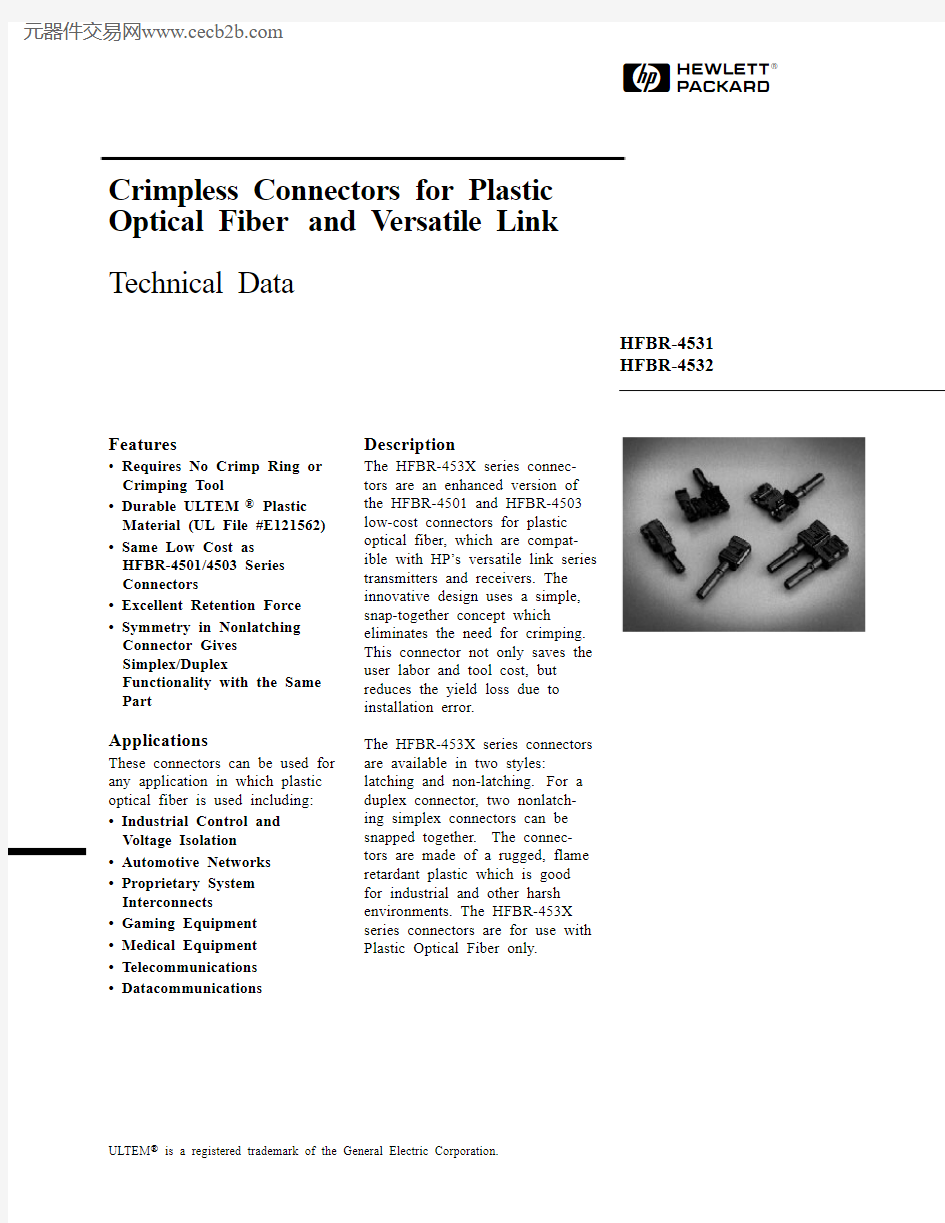
The HFBR-453X series connec-tors are an enhanced version of the HFBR-4501 and HFBR-4503 low-cost connectors for plastic optical fiber, which are compat-ible with HP’s versatile link series transmitters and receivers. The innovative design uses a simple, snap-together concept which eliminates the need for crimping. This connector not only saves the user labor and tool cost, but reduces the yield loss due to installation error.
The HFBR-453X series connectors are available in two styles: latching and non-latching.For a duplex connector, two nonlatch-ing simplex connectors can be snapped together.The connec-tors are made of a rugged, flame retardant plastic which is good for industrial and other harsh environments. The HFBR-453X series connectors are for use with Plastic Optical Fiber only.
ULTEM?
is a registered trademark of the General Electric Corporation.
Termination Guide
Step-by-Step Plastic Cable Connectoring Instructions
The following step-by-step guide describes how to terminate plastic fiber optic cable. It is ideal for both field and factory installa-tions. Connectors can be easily installed on cable ends with
standard tools such as wire strippers and cutters.
Finishing the cable is accom-plished with the Hewlett-Packard HFBR-4593 Polishing Kit, consisting of a polishing fixture, 600 grid abrasive paper and 3 μm pink lapping film (3M Company, OC3-14). The connector can be used immediately after polishing. The following materials are needed for plastic fiber termination:
1. Plastic optical fiber cable
(Example: HFBR-RUD500)
2. Wire cutters or scissors
3. 16 gauge wire stripper
(Example: Ideal Stripmaster
type 45-092)
4. HFBR-4593 polishing kit
(optional)
5. Crimpless connectors
Step 1: Stripping the Fiber The zip cord structure of the duplex cable permits easy separation of the channels. The channels should be separated a minimum of 100 mm (4 in) to a maximum of 150 mm (6 in) back from the ends to permit connec-toring, polishing and cable end flexibility.
After cutting the cable to the desired length, strip off approximately 7 mm (0.3 in) of the outer jacket with the 16 gauge wire strippers.When using the duplex connector
arrangement, the separated
duplex cable should be stripped
to roughly equal lengths on each
cable end.
For the non-latching version
(HFBR-4531), the same
connector is used for simplex and
duplex arrangement. No crimping
is necessary. The top half of the
connector will snap into the
ferrule half to secure the fiber.
Step 2: Putting on the
Connector
Place the connector on each end
of the fiber, and slide the
connector down until the fiber
jacket stops it.The fiber should
protrude no less than 1.5 mm
(0.06 in) from the end of the
connector.
To install simplex connectors flip
the top half of the connector over
and snap it into the ferrule half
(with your fingers).When the top
half latches inside the body of the
ferrule half, proper connector-to-
cable attachment is achieved.
For duplex connector installation
place one connector on top of the
other, so that the top half of each
connector is over the ferrule half
of the opposite connector.
Manually press connectors
together in the center of the
arrangement. Then latch by
pressing on the sides of each
connector.As with the simplex
version, connectors are secured
when top halves latch into the
ferrule halves.
Step 3: Trimming and
Polishing
Any fiber in excess of 1.5 mm
(0.06 in) protruding from the
connector end should be cut off
with wire cutters or scissors.
Insert the connector fully into the
polishing fixture with the
trimmed fiber protruding from
the bottom of the fixture. This
plastic polishing fixture can be
used to polish two simplex
connectors simultaneously or one
duplex connector.
Note: The four dots on the bottom of the polishing fixture
are wear indicators. Replace the polishing fixture when any dot is no longer visible.
Press the polishing tool down on the 600 grit abrasive paper. Polish the fiber using a figure eight pattern until the connector is flush with the bottom of the polishing fixture. Wipe the connector and fixture with a clean cloth or tissue.
HFBR-4593 Polishing Kit
Note: Use of the pink lapping
film fine polishing step results
in approximately 2 dB
improvement in coupling
performance of either a
transmitter-receiver link or a
bulkhead/splice over a 600 grit
polish alone. This fine polish is
comparable to the Hewlett-
Packard factory polish. The
fine polishing step may be
omitted for short link lengths. Step 4: Finishing
Place the flush connector and
polishing fixture on the dull side
of the 3 μm pink lapping film and
continue to polish the fiber in the
same figure eight pattern for
approximately 25 strokes. The
fiber end should be flat, smooth
and clean.
Connector Mechanical Characteristics
Notes:
1. Storage and operating temperatures refer to the ranges over which the connectors can be used when not subjected to mechanical stress. Installation temperature refers to the ranges over which connectors may be installed onto the fiber and over which connectors can be connected and disconnected from the transmitter and receiver modules.
HFBR-4531/4532
Absolute Maximum Ratings
Parameter Symbol Min.Max.Unit Note Storage Temperature T S -4085°C 1Operating Temperature T O -4085°C 1Installation Temperature
T I
70
°C
1
Mechanical Dimensions
All dimensions are in inches and (millimeters)HFBR-4531 (Nonlatching):
HFBR-4531 in Duplex Configuration
HFBR-4532 (Latching):
H
For technical assistance or the location of your nearest Hewlett-Packard sales office, distributor or representative call: Americas/Canada: 1-800-235-0312 or 408-654-8675
Far East/Australasia: (65) 290-6305 Japan: (81 3) 3331-6111
Europe: Call your local HP sales office listed in your telephone directory. Ask for a Components representative.
Data subject to change.
Copyright ? 1996 Hewlett-Packard Co. Printed in U.S.A.5965-1659E (9/96)