The_6-Dof_2-Delta_parallel_robot1
R obotica (1997) volume 15,pp 407 –416.Printed in the United Kingdom ÷1997 Cambridge University Press
T he 6-Dof 2-Delta parallel robot
https://www.360docs.net/doc/557520180.html,llemand,A.Goudali and S.Zeghloul
L aboratoire de Me′c anique des Solides ,U .M .R .C .N .R .S 6610,SP 2M I -B.P .17986960F UTUROSCOPE Ce′d ex (F rance )
S UMMARY
I n this paper,we will present a new 6-DOF parallel robot u sing a set of two Delta structures.An ef f ective method i s proposed to establish explicit relationships between the e nd ef f ector co-ordinates and the active and passive joint v ariables.A simulation of the 2-Delta robot on a C.A.D. R obotics system will also be presented.This simulation w ill allow us to validate the cohesion of our calculations, a nd to show the workspace depending on the mechanical l imits on passive joints variables.Finally,an approach is p roposed to study the in?uence of small clearances of the p assive joint on the precision of the position and rotation o f the ef f ector.This approach is based on a concept s imilar to that of Yoshikawa’s manipulability.
K EYWORDS :P arallel robot ;Uncoupled ;Modelization ; W orkspace ;Ellipsoid of clearance.
1.I NTRODUCTION
P arallel robots have been the subject of several studies d ue to the considerable interest they have demonstrated t hrough their lightness,rigidity and rapidity.These p articular properties open the door to all spatial a pplications where mass problems are particularly c rucial.They are also used as robot end ef f ector.The ?rst parallel robot structure dates from 1939 when P ollard1proposed a parallel structure to paint cars.In 1949,Gough proposed an articulated machine to test t ires.Next Stewart2suggested the utilisation of this s tructure as a movement generator for ?ight simulators.
I t was also used by Reboulet,3and by Merlet4as a c ompliant wrist of a robot.Amongst spatial operators of 3d.o.f.,the Delta structure designed by Clavel5 c onstitutes technological innovation.Other 3 d.o.f. p arallel structures have been developed.Three of these a re the parallel robot H-Star developed by Herve′,6the r obot Speed R-Man developed by Reboulet7and the s tructure proposed by Jacquet.8
W e will put forward the 2-Delta robot which in p rinciple,constitutes a new and original structure.This r obot is entirely parallel and possesses 6 d.o.f.Its f eatures lie in mechanical uncoupling of translation and o rientation motions.This property is what dif f erentiates i t from other traditional 6 d.o.f parallel robots or from t he one issued from the Delta structure.This paper p artially treats the dif f erent studies that have been c arried out on the 2-Delta robot and which have been p resented in reference 9.2.P RINCIPLE OF THE 2-DELTA STRUCTURE
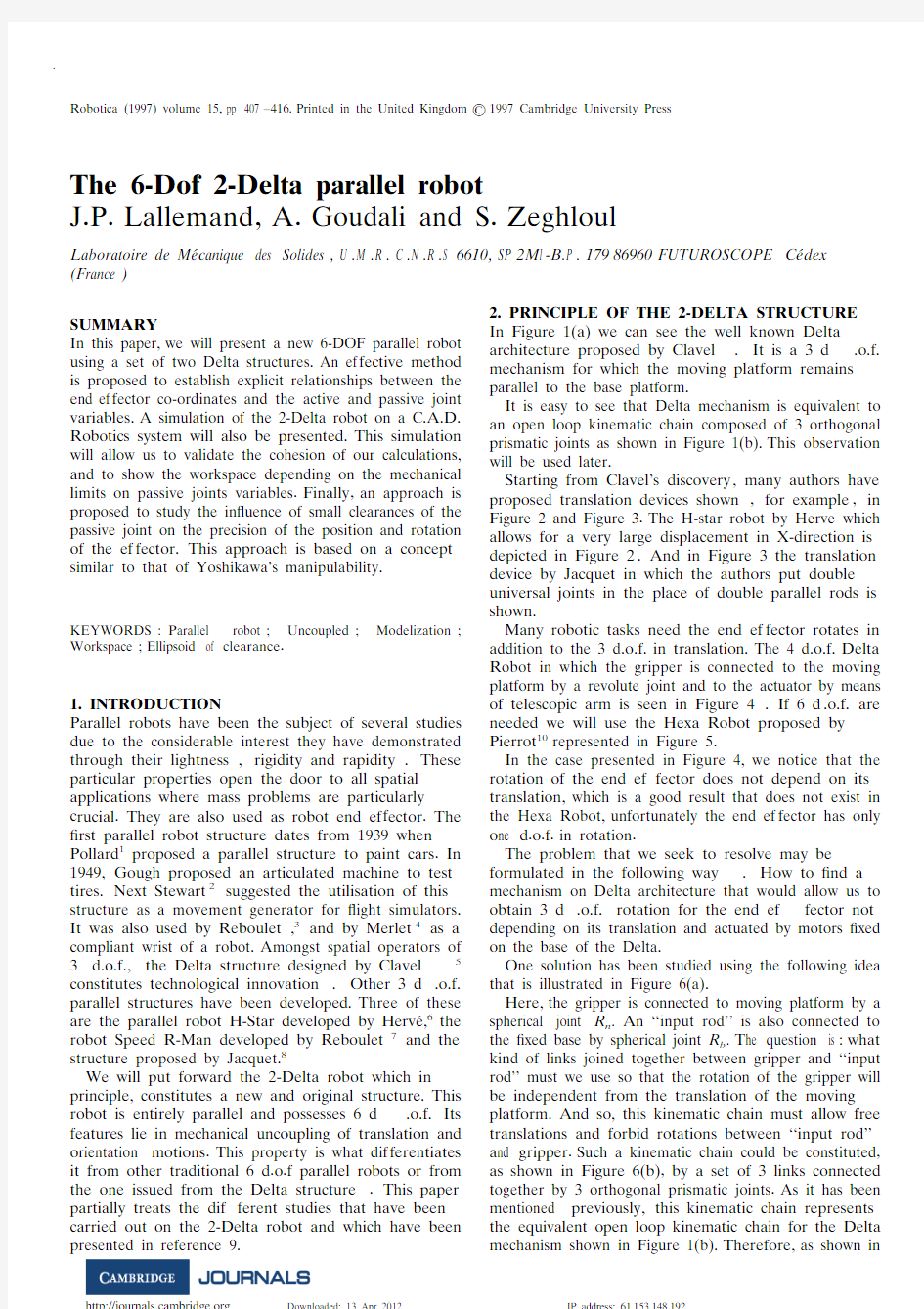
I n Figure 1(a) we can see the well known Delta
a rchitecture proposed by Clavel.It is a 3 d.o.f. m echanism for which the moving platform remains p arallel to the base platform.
I t is easy to see that Delta mechanism is equivalent to
a n open loop kinematic chain composed of 3 orthogonal p rismatic joints as shown in Figure 1(b).This observation w ill be used later.
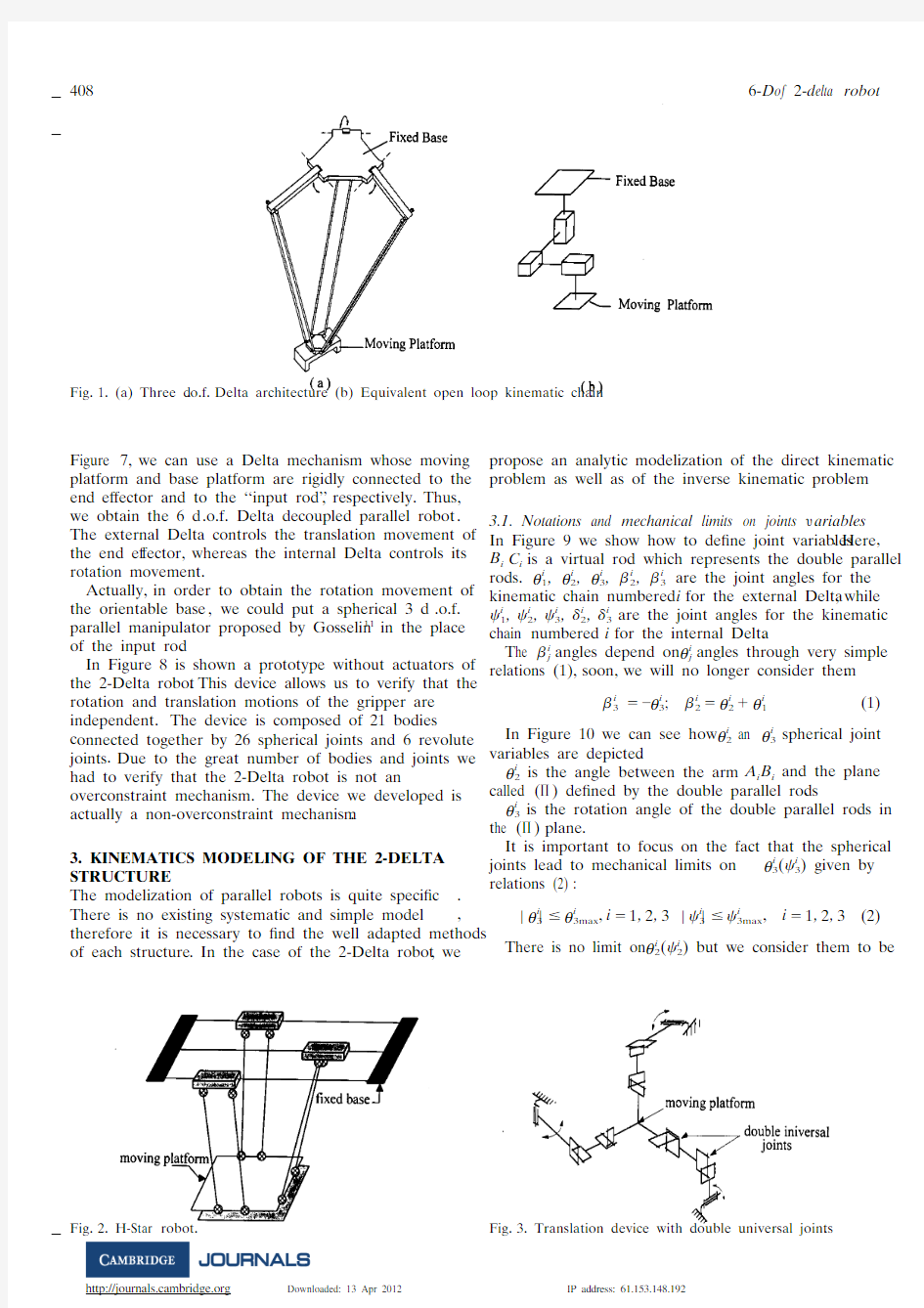
S tarting from Clavel’s discovery,many authors have p roposed translation devices shown,for example,in F igure 2 and Figure 3.The H-star robot by Herve which a llows for a very large displacement in X-direction is d epicted in Figure 2.And in Figure 3 the translation d evice by Jacquet in which the authors put double u niversal joints in the place of double parallel rods is s hown.
M any robotic tasks need the end ef f ector rotates in a ddition to the 3 d.o.f.in translation.The 4 d.o.f.Delta R obot in which the gripper is connected to the moving p latform by a revolute joint and to the actuator by means o f telescopic arm is seen in Figure 4.If 6 d.o.f.are n eeded we will use the Hexa Robot proposed by P ierrot10represented in Figure 5.
I n the case presented in Figure 4,we notice that the r otation of the end ef f ector does not depend on its t ranslation,which is a good result that does not exist in t he Hexa Robot,unfortunately the end ef f ector has only o ne d.o.f.in rotation.
T he problem that we seek to resolve may be f ormulated in the following way.How to ?nd a m echanism on Delta architecture that would allow us to o btain 3 d.o.f.rotation for the end ef f ector not d epending on its translation and actuated by motors ?xed o n the base of the Delta.
O ne solution has been studied using the following idea t hat is illustrated in Figure 6(a).
H ere,the gripper is connected to moving platform by a s pherical joint R n.A n ‘‘input rod’’ is also connected to t he ?xed base by spherical joint R b.T he question is :what k ind of links joined together between gripper and ‘‘input r od’’ must we use so that the rotation of the gripper will b e independent from the translation of the moving p latform.And so,this kinematic chain must allow free t ranslations and forbid rotations between ‘‘input rod’’a nd gripper.Such a kinematic chain could be constituted, a s shown in Figure 6(b),by a set of 3 links connected t ogether by 3 orthogonal prismatic joints.As it has been m entioned previously,this kinematic chain represents t he equivalent open loop kinematic chain for the Delta m echanism shown in Figure 1(b).Therefore,as shown in
F ig.1.(a) Three d.o.f.Delta architecture (b) Equivalent open loop kinematic chain.
F igure 7,we can use a Delta mechanism whose moving p latform and base platform are rigidly connected to the e nd ef f ector and to the ‘‘input rod’’,respectively.Thus, w e obtain the 6 d.o.f.Delta decoupled parallel robot. T he external Delta controls the translation movement of t he end ef f ector,whereas the internal Delta controls its r otation movement.
A ctually,in order to obtain the rotation movement of t he orientable base,we could put a spherical 3 d.o.f. p arallel manipulator proposed by Gosselin11in the place o f the input rod.
I n Figure 8 is shown a prototype without actuators of t he 2-Delta robot.This device allows us to verify that the r otation and translation motions of the gripper are i ndependent.The device is composed of 21 bodies c onnected together by 26 spherical joints and 6 revolute j oints.Due to the great number of bodies and joints we h ad to verify that the 2-Delta robot is not an o verconstraint mechanism.The device we developed is a ctually a non-overconstraint mechanism.
3.K INEMATICS MODELING OF THE 2-DELTA S TRUCTURE
T he modelization of parallel robots is quite speci?c. T here is no existing systematic and simple model, t herefore it is necessary to ?nd the well adapted methods o f each structure.In the case of the 2-Delta robot,we
F ig.2.H-Star robot.p ropose an analytic modelization of the direct kinematic p roblem as well as of the inverse kinematic problem.
3.1.N otations and mechanical limits on joints ?a riables
I n Figure 9 we show how to de?ne joint variables.Here, B i C i i s a virtual rod which represents the double parallel r ods.θi1,θi2,θi3,?i2,?i3are the joint angles for the k inematic chain numbered i f or the external Delta,while ?i1,?i2,?i3,?i2,?i3are the joint angles for the kinematic c hain numbered i f or the internal Delta.
T he ?i j a ngles depend on θi j a ngles through very simple r elations (1),soon,we will no longer consider them.
?i3 ? ?θi3;?i2?θi2?θi1(1) I n Figure 10 we can see how θi2an θi3spherical joint v ariables are depicted.
θi2is the angle between the arm A i B i a nd the plane c alled (?) de?ned by the double parallel rods.
θi3is the rotation angle of the double parallel rods in t he (?)plane.
I t is important to focus on the fact that the spherical j oints lead to mechanical limits on θi3(?i3) given by r elations (2) :
?θi3??θi3max,i?1,2,3??i3???i3max,i?1,2,3(2) T here is no limit on θi2(?i2) but we consider them to be
F ig.3.T ranslation device with double universal joints.
F ig . 4 .F our d . o . f . Delta robot .
d if f erent from zero in order to avoid singular c on?gurations .
θ i 2 ? 0 , i ? 1 , 2 , 3 ? i 2 ? 0 , i ? 1 , 2 ,3(3)
F inally , there are also mechanical limits on θ i 1 ( ? i 1)so t hat :
θ i 1 m in ? θ i 1 ? θ i 1 m ax , i ? 1 , 2 , 3
? i 1 m in ? ? i 1 ? ? i 1 m ax , i ? 1 , 2 , 3(4)
T he end ef f ector coordinates or task coordinates are :
—the position vector of the point V r eferred to the ?xed
f rame R 0. I t is written as O V 0
? ( X ? , Y ? , Z ? ) T ,t he index 0 recalls the reference frame . —the Bryant angles ? ? ( ? 1 , ? 2 , ? 3 ) T o f the frame R ? a ttached to the end ef f ector with respect to ?xed frame .
T he control variables are θ
i 1for i e quals 1 to 3 noted as
θ 1vector θ 1 ? ( θ 1 1 , θ 2 1 , θ 3 1 ) T
. T he three other active joint v ariables are the Bryant angles of the frame attached to t he orientable base with respect to the ?xed frame .These
a ngles are written as ? ? ( ? 1 , ? 2 , ? 3 )
T .S imilar notations a re used for passive joint variables as follows :
θ 2 ? ( θ 1 2 , θ 2 2 , θ 3 2 ) T , θ 3 ? ( θ 1 3 , θ 2 3 , θ 3 3 ) T , ? 1 ? ( ? 1 1 , ? 2 1 , ? 3
1 ) T , ?
2 ? ( ? 1 2 , ? 2 2 , ?
3 2 ) T , ? 3 ? ( ? 1 3 , ? 2 3 , ? 3 3 ) T
. D ue to the property of the Delta mechanism it is
o bvious that ? e quals ?. B ecause of the mechanical limit o f the spherical joint located at D , t he angle between Z 0a nd Z ? a xis is lower than ? m ax .Thus , the active joint v ariables ? 1and ? 2
are subject to the following
F ig . 5 . T he six d . o . f . Hexa robot .F ig . 6 . P rinciple of uncoupling movement between orientation
a nd translation of the gripper
.
F ig . 7 . T he 6 d . o . f . 2-Delta robot .
F ig.8.P rototype of the 2-Delta architecture.
c onstraint :
c os?1иc os?2?c os?m ax(5) I n order to obtain relationships between geometrical
t erms previously described we must use some results
f ound by Clavel for the Delta architecture.Clavel gave c losed-form relationships connectin
g cartesian coordin-
a tes of the point D t o the control variables θ1and v ice-versa.These relationships we will use are presented i n the following way :
D irect k inematicséO D0?f(θ1)(6)
I nverse kinematicséθ1?f?1(O D0)(7)
3.2S olution to the direct kinematic problem for the
2-D elta robot
T he solution to the direct kinematic problem gives the
p osition and the orientation of the gripper as well as
p assive joint variables of the external and the internal
s tructure when control joint variables are known.Given t erms are θ1and ?,u nknowns are O V0,?,θ2,θ3,?1,?2,?3.
S teps of the calculation are as follows :
—S tep 1 .T he location of point D i s calculated by means
o f Clavel’s relation (6)—S tep 2 .C alculation of the location of point V g iven by t he following relation :
O V0?O D0?R(?)D V0?(8) w here R(?) is the matrix transformation in Bryant a ngles from frame R0?with respect to frame R0and D V0??(0,0 , DV)T.
—S tep 3 .D etermination of the gripper orientation ?.I t i s obvious that :
???(9)—S tep 4 .C alculation of passive joint variables θ2and θ3 (external Delta).
C onsidering the kinematic chain numbered i,w e write t he vector A i C i i n two dif f erent ways :
A i C0i?A i O0?O D0?D C0i(10)
A i C0i?R(Z0,?i)R(Y A i,θi1)
?[A i B i i?R(Y i,θi2)R(Zπ,θi3)B i C r i i](11) R elation (10) involves points A i,O ,D a nd C i,i n which e ach term is known.Relation (11) involves points A i,B i a nd C i a nd rotation matrices between body frames d epending on unknowns θi2and θi3.T hese relations lead t o both of the following equations
s inθi3?k1
c osθi3(k2c osθi3?k3s inθi2)?k4
w hose solution results in θi2and θi3.W e complete this c omputation three times since i e quals 1 to 3.
—S tep 5 .C alculation of ?1(internal Delta).
F irstly,we determine the position vector of point E r eferred to the orientable base frame R0?by the following r elation :
O?E0??O?O0??R T(?)O D0?D E0?(13) w here O?O0??(0,0,?O O?)T,DE0??(0,0 , DE)T.T hen,?1is a given according to Clavel’s relation (7) :
?1?f?1(O?E0?)(14)—S tep 6 .C alculation of ?2and ?3(internal Delta).
W e use the same procedure as in step 4 after having e xpressed vector H i F i r eferred to orientable base frame R0?i nstead of vector A i C i r eferred to ?xed base frame R0.
3.3.S olution to the in?e rse kinematic problem for the
2-D elta robot
I n order to obtain the closed-form solution to the inverse k inematic we will use the following procedure.
K nown terms are O V0,t he position vector point V, a nd the gripper orientation ?.U nknowns are the control j oint variables θ1and ?,a nd the passive joint variables θ2,θ3,?1,?2,?3.
—S tep 1g ives ?b y
???(15)
F ig.9.D e?nition of joints parameters.
—S tep 2 .C alculation of position vector of point D r eferred to frame R0:
O D0?O V0?R(?)D V0?(16)w here R(?)and D V0?are previously de?ned.
—S tep 3 .C alculation of θ1from the Clavel’s relation (7).
F ig.10.D e?nition of angles θi2,θi3.
F inally , the passive joint variables θ 2, θ 3, ? 1, ? 2, ? 3 a re obtained from the procedure (s teps 4 ,5 ,6)described i n the direct kinematic problem .3.4.‘‘C hecking ’’ o f the modeling D ue to the complexity of kinematic modeling ,many m iscalculations were likely to appear . Thus it was n ecessary to check all the relationships . To this end ,we b uilt the 2-Delta architecture on a C . A . D .Robotic
S imulator developed in our Laboratory 1 2
as it is shown in F igure 11 . If the kinematic relationships are correct we w ill see that bodies remain connected together at joints w hen the mechanical structure is actuated . These ?gures a llow us to check that the kinematic modeling is right .4.G ENERATION OF POSITION WORKSPACE A ND ORIENTATION WORKSPACE S tarting from the knowledge of kinematic modeling we m ay obtain the workspace of the 2-Delta robot which d epends on the mechanical limits of both active and p assive joint variables . T o determine the position or the orientation w orkspace of the 2-Delta robot , we will use the
t echnique of discretization 1 3
which consists , in this case , o f the de?nition of the position workspace , of ?xing the o rientation of the end ef f ector and ?nally seeking all p ositions that can be reached by the end ef f ector , r egardless of the cross section chosen . In the case of the g eneration of workspace orientation , we will consider the e nd ef f ector position will be ?xed .Then , we will seek all p ossible orientations . We have separated this space into t wo distinct subspaces :
W orkspace without joint limits or theoretic space
. w orkspace with joint limits or space with constraints .
4.1.R elationship between space of theoretical position a nd space with constraints T he introduction of limits (relation (2) to (5)) on the p assive and active joint variables reduces the workspace o f the 2-Delta structure in comparison to the theoretical s pace . We have attempted to investigate the proportion t hat represents space with constraints in comparison to t heoretical space . These two spaces in a cross section d e?ned by plane X ? ? 0 and plane Z ? ?450m m are i llustrated in Figure 12 .
F or a given cross section of the workspace (for
e xample Z ? ?c onstant) , we can evaluate the reachable s urface by de?ning a workspace position factor ? z a s :
? z ?
S p ,c
S p ,t
(17)
w here , S p ,t i s the surface of theoretical space in the plane
Z ? ?c onstant and S p ,c i s the surface of space with c onstraints in the same plane . It is obvious that ? z d epends on Z ?a nd orientation ?.F or example , in Figure 13 , ? z v ersus Z ? f or dif f erent orientations of the end e f f ector are shown .4.2.C ross section of theoretical orientation space I n order to obtain a representation in the plane , we will ?x one of the three orientation angles of the gripper ( ? 3 ?0), t hen will seek all possible orientations for a g iven position of point V f or both cases , without and with m echanical limits on joints . In Figure 14 , (a) and (b) s how two examples of two dif f erent cartesian coordinates o f point V . A s we de?ned in (17) the position factor we could d e?ne the orientation factor ? 0as :
? 0 ?
S o ,c
S o ,t
(18)
w here , S o ,t i s the surface of the theoretical orientation
s pace and S o ,c i s the surface of the orientation space with c onstraints . It is obvious that ? 0 depends on the position c hosen for the point V . I n Figure 15 , ? 0versus Z ?w hen t he point V b elongs to Z 0 axis is shown . 5 . M ODELIZATION OF THE CLEARANCES IN P OSITION AND IN ORIENTATION I n this section , we will consider the in?uence of the small v ariations of the rod lengths of the 2-Delta around their f ace values on translation and rotation vectors of the end e f f ector . We will assume that these variations express the e xistence of localized clearance in the passive joints of t he rods . Afterwards we will de?ne the ellipso? ¨d es of c learance based on the concept of the manipulability e llipso?¨d s . 1
3
F ig .11 . S imulation of the 2-Delta robot .
F ig.12.S uperposition of the theoretical space and the space with constraints (a) cross section for plane X V?0 (b) cross section for
p lane Z
V?450m m
.
5.1.P roblem statement and simplifying hypotheses
I n order to reduce the problem complexity,it seems u seful to propose some simplifying hypotheses concern-i ng the geometry of the robot,as well as its physical p arameters.We suppose that :
–e ach parallelogram is made of one rod.
–a ll simulations are carried out taking into considera-t ion that active joints are without clearances in each c hosen con?guration,and that the variation of the p osition and the orientation of the ef f ector are due solely t o variations of rod lengths which act as linear actuators. W e will separate the modelization of clearance into t wo parts :
–p osition clearance model which gives position v ariation of the ef f ector solely for clearance at the p assive joint of each rod of the external structure.
–o rientation clearance model which gives orientation v ariation of the ef f ector solely for clearance at the p assive joint of the internal structure.
5.2.P osition clearance model
W e de?ne the position clearance model as,
?X V?J p?L1(19) w here :
?X??(?x V,?y V,?z V)T r epresents the variations of the p osition of the end ef f ector.
?L1?(?L11,?L21,?L31)T r epresents the elementary length v ariations of the rods found in the external structure.
J p i s the Jacobian matrix of partial derivatives of X V w ith r espect to L1,o f dimension 3?3.
T erms of J p h ave complex expressions,thus we must
F ig.13.P osition factor on the axis Z0.
F ig .14 . S uperposition of the orientation and with stops theoretical space for two sets of coordinates of point V .
u se the symbolic calculation software (Maplle V )to o btain these expressions . I n Figure 16 there is a representation of the ellipsoid
o f clearance de?ned by ? X
T ? (J J T ) ? 1 ? X ? ? 1.W hen the e f f ector moves along the Z 0axis , we see that this axis c onstitutes an axis of revolution for these ellipso?
¨d s the ?rst two eigenvalues of each matrix (J J T ) ? 1
always r emain equal ( ? 1 ? ? 2 ) whatever the position may be . T his leads to an equitable distribution of the clearance in t he plane [ x 0 , y 0 ].S imilarly , we observe that the volume o f the ellipso? ¨ d s of clearance increases considerably as t he position of the ef f ector moves along the axis z 0.T his i s due to the vicinity of the singular con?gurations .On t he other hand , for postures of the wrist following the a xis x 0 or the axis y 0 (that is not shown here) ,the e llipsoids change in dimension and in form depending on t heir relation to the robot con?guration . In fact ,the c learance in these postures does not have the same ef f ect i n all directions . T
he exploitation and the application of these results
F ig .15 . O rientation factor on the axis Z 0 .
a re very extensive . They allow , for example , a designer
t o know in advance the value of error in a position of the e nd ef f ector according to the structure con?guration . T hey also allow us to select the best con?gurations to e xecute a task inside the workspace .5.3.O rientation clearance model I n this section , we will deal with the clearance at the p assive joint of the internal structure on the gripper o rientation . To obtain this model , we deduce it from the d irect kinematic model which gives orientation coordin- a tes of the gripper in relation to the rod lengths of the i nternal structure . Therefore we obtain :
?? ? J 0 ? L 2
(20)
w here :?? ? (??1 ,??2 ) T r epresents the variation of the orienta- t ion of the ef f ector with ? 3 ? 0 .
? L 2 ? ( ? L 1 2, ? L 2 2 , ? L 3 2 ) T
r epresents elementary length v ariations of the rod for internal Delta . J 0 is the Jacobian matrix of partial derivatives of ? w ith r espect to L 2, o f dimension 2 ? 3 . W e have studied ellipses of clearance in dif f erent p ositions .Presently , in Figure 17 , we show the results of t wo ellipses obtained for two extreme positions on the a xis Z 0 . W e notice in general that eigenvalues which represent d imensions of clearance ellipse are roughly equal w hatever the con?guration . This shows that the u ncertainty in orientation is almost the same in all p ostures (except postures close to single con?guration) . I f we consider the obtained ellipses along the axis z 0for o rientation to be zero , we will observe that the surface of o rientation uncertainty is represented by a circle since t he two eigenvalues are equal , which shows that no d irection is penalized . On the other hand ,for c on?gurations away from the axis z 0, w e notice a d issymmetry represented by a change of ellipse
F ig .16 . D imensions and morphology of the ellipsoids of position clearance on the axis Z 0
.
F ig .17 . D imensions and morphology of clearance ellipses in orientation on the axis Z 0 .
m orphology , which explains the uncertainty dif f erence d ue to the clearance that is not the same in all directions . T his study shows that the existence of passive joints , w hich in general characterize parallel robots , can be a s ource of error and perturbation and susceptible to p roducing position and orientation imprecisions of the e f f ector . In the case of the 2-Delta robot , we have shown f or distanced postures of singular con?gurations that the c learance has more in?uence on the position of the e f f ector than on its orientation . In this section we have p resented a methodology that allows one to identify and s elect con?gurations so that the ef f ect of the clearance is m inimized . Similarly the introduction of the ellipso? ¨d es o f clearance (or ellipses of clearance) allows for a c omplete understanding of the general volume of the u ncertainty in function of the con?guration .6.C ONCLUSION T he main objective of this study consisted of examining a n ew parallel robot family , characterized by the u ncoupled mechanics between the translation and r otation of the wrist , and proposing approaches to solve p roblems in design ,modelization , joint limits and i n?uence of the clearance . The study that we expect to d o in the future will deal with the possible collisions
b etween the internal and external Delta . With this aim in
m ind , we will use our CAD Robotic Simulator which c ontains a software especially designed for collision a voidance .R eferences 1 . W . Pollard and Evanston , ‘‘Position-Controlling Appara-t us’’ A pplication A pril 22 ,1938 . Serial No .203 ,634 (Renewed June 14 ,1940) . 2 . D .Stewart , ‘‘A Platform with six degrees of freedom’’ I ME P roc .80 , P art I (15) 371 – 386 (1965) . 3 . C .Reboulet ,‘‘Mode ′ l isation des robots paralle `l es’’ T echniques de la Robotique (Herme ` s ,Paris ,1988) V ol .1 ,p p .257 –284) . 4 . J . P .Merlet , ‘‘Commande par retour d’ef f ort’’ T he `s e (Universite ′ de Paris VI ,1986) . 5 . R .Clavel , ‘‘Une nouvelle structure de manipulateur p aralle ` l e pour la robotique le ′g e `r e’’ R AIRO APII 23 ,N o . 6 ,501 –519 (1989) . 6 . J . M . Herve and F .Sparacino , ‘‘Structural synthesis of
p arallel robot generating spatial translation’’ I CAR 91,P isa , Italy pp .808 –813 (1991) . 7 . C .Reboulet , C .Lambert , N . Nombrail and N .Delpech , ‘‘Etude et mise en oeuvre du robot SPEED-R-MAN’’R apport interme ′d iaire MRT /D ERA (December ,1991) . 8 . P .Jacquet , M .Dahan , G . Danescu and C .Garcin ,‘‘Robot p aralle `l e a ` actionneurs line ′a ires L e Congre `s Franc ?a is de M e ′c anique ,L ille , France (1991) pp .377 –380 .
9.A.Goudali,‘‘Contribution a`l’Etude d’un Nouveau
R obot Paralle`l e 2-Delta a`Six Degre′s de Liberte′
a vec de′c ouplage’’ T he`s e (l’Universite′de Poitiers,
1995).
10.F.Pierrot,A.Fournier and P.Dauchez,‘‘Towards a fully
p arallel 6 d.o.f.robot for high speed,application’’ P roc .of t he 1991I EEE ICRA ,S aremento,California (April,1991) p p.1288 –1293.
11.C.Gosselin and https://www.360docs.net/doc/557520180.html,voie,‘‘On the kinematic design of
s pherical 3-dof parallel manipulator’’ I nt .J .Robotics R esearch 12 ,N o.4,394 –402 (1993).12.S.Zeghloul,‘‘De′v eloppement d’un syste`m e de C.A.O.-
R obotique inte′g rant la plani?cation de ta?c hes et la synte`s e
d e sites robotise′s’’ T he`s e d e Doctorat d’Etat (Poitiers,
1991).
13.Y.C.Tsai and A.H.Soni,‘‘An algorithm for the
W orkspace of a General n-R Robot’’ A SME J .of M echanisms , Transmissions an Automation in Design 105 , N o.1,52 –57 (1983).
14.T.Yoshikawa,‘‘Manipulability of Robotic Mecanisms’’
P roceeding of the 2n d Int . Symposium on Robotic Research (1984) pp.439 –446.