tunnel stability and arching effects during tunnelling in soft clayey soil
Tunnel stability and arching e?ects during tunneling in soft clayey soil
C.J.Lee
a,*
,B.R.Wu b ,H.T.Chen a ,K.H.Chiang
a
a Department of Civil Engineering,National Central University,No.300,Jung-da Rd.,Chungli,Taoyuan 32054,Taiwan b
National Science and Technology Center for Disaster Reduction,3F.,No.106,Sec.2,HoPing E.Rd.,Taipei 106,Taiwan
Received 5October 2004;received in revised form 2April 2005;accepted 5June 2005
Available online 8August 2005
Abstract
A series of centrifuge model tests and numerical simulations of these tests were carried out to investigate the surface settlement troughs,excess pore water pressure generation,tunnel stability and arching e?ects that develop during tunneling in soft clayey soil.The two methods were found to provide consistent results of the surface settlement troughs,excess pore water generation,and the overload factors at collapse for both single and parallel tunneling.The arching ratio describes the evolution of the arching e?ects on the soil mass surrounding tunnels and can be derived from the numerical analysis.The boundaries of the arching zones for both single tunneling and parallel tunneling were determined.In addition,the boundaries of the positive and negative arching zones were also proposed.
ó2005Elsevier Ltd.All rights reserved.
Keywords:Arching e?ect;Tunnel stability;Centrifuge modeling;Numerical modeling
1.Introduction
Tunneling in soft clayey soils has become very pop-ular in recent years because it is one of the best con-struction methods for building mass rapid transit systems and sewage collection systems in densely pop-ulated cities.As the face of a tunnel is advanced,a means of supporting the ground close to the face may be needed;without such support,collapse might occur due to gross plastic deformation of the soil.Moreover,tunneling inevitably induces varying de-grees of ground movement towards the tunnel opening and results in detrimental e?ects on nearby facilities,such as shallow foundations,piles,existing tunnels and other pipeline systems.Taking appropriate mea-sures to protect nearby facilities before excavation is an important part of engineering practice.The predic-tion of tunneling-induced ground movements during excavation of soft ground tunnel has been carried out using various methods,including empirical meth-ods derived from ?eld observations (Peck,1969;Clough and Schmidt,1981)and centrifuge modeling (Mair et al.,1981;Wu and Lee,2003;Lee et al.,2004),or numerical and analytical methods (Lee and Rowe,1991).
Terzaghi (1943)explained how stress transfer from yielding parts of a soil mass to adjacent non-yielding parts leads to the formation of an arching zone.This problem has two modes of displacement,depending on whether the trap door is translated into the soil (passive mode)or away from it (active mode).The passive mode can be used for the evaluation of the uplift force of anchors,or of any buried structure that can be idealized as an anchor.The active mode can be used to study the gravitational ?ow of granular mate-rial between vertical walls (the silo problem)or the ground pressure on tunnel https://www.360docs.net/doc/7013361648.html,danyi and Hoy-aux (1969)performed a series of model trap-door tests
0886-7798/$-see front matter ó2005Elsevier Ltd.All rights reserved.doi:10.1016/j.tust.2005.06.003
*
Corresponding author.Tel.:+88634227151x34135;fax:+88634252960.
E-mail address:cjleeciv@https://www.360docs.net/doc/7013361648.html,.tw (C.J.Lee).
https://www.360docs.net/doc/7013361648.html,/locate/tust
Tunnelling and Underground Space Technology 21(2006)
119–132
Tunnelling and
Underground Space Technology
incorporating Trenchless Technology Research
under1g conditions in order to check the validity of the classic bin theory.Handy(1983)analyzed soil arching action behind retaining walls,and Wang and Yen(1973)carried out this analysis for slopes.Nakai et al.(1997)performed a series of physical model tests under1g conditions and carried out numerical analy-sis of these tests to investigate the arching e?ect.They found that the results obtained from the model tests were in good agreement with those obtained from the numerical analysis.Park and Adachi(2002)per-formed model tests under1g conditions to simulate tunneling events in unconsolidated ground with vari-ous levels of inclined layers.They found that remark-able non-symmetrical distributions of the earth pressure arose when a tunneling event took place in inclined layers with60°of inclination.Stone and New-son(2002)presented the results of a series of centri-fuge tests designed to investigate the e?ects of arching on soil–structure interaction.Koutsabeloulis and Gri?ths(1989)implemented a?nite element method to investigate the trap-door problem.The con-cept of soil arching was recently adopted in the anal-ysis of the mobilization of resistance from passive pile groups subjected to lateral soil movement(Chen and Martin,2002).
When tunneling is conducted in the vicinity of exist-ing pile foundations,the axial load transfer mechanism and failure mode on existing piles vary depending on the distance between the existing piles and the new driv-ing tunnel and relative elevation of the piles with respect to the centerline of the tunnel(Lee and Chiang,2004). These behaviors result from the complicated redistribu-tions of stress around tunnels during tunneling.Hence, the stress distribution in the vicinity of a tunnel or of several tunnels stacked closely in an underground sta-tion needs to be established before appropriate protec-tion measures for nearby existing piles can be implemented.By deepening our understanding of the arching e?ect in various geotechnical problems,we can improve the design of the protection measures required for existing underground structures nearby new tunneling.
Both centrifuge and numerical modeling were used in the study.The stability of a tunnel,the movements of soil mass,the evolution of stress on the soil mass around a tunnel,and the boundaries of the arching zone during tunneling in clayey soils are investigated and discussed. Firstly,a series of centrifuge model tunnel tests was con-ducted.A?nite di?erence program(FLAC)was then chosen for numerical analysis of the system described by the centrifuge model to provide insight into the arch-ing mechanism and the boundaries of the arching zone during tunneling.Finally,the results from the numerical modeling and the measurements from the centrifuge modeling were compared in order to assess their predictions.2.Centrifuge and numerical modeling
2.1.Centrifuge modeling
The basic principle of centrifuge modeling is to recre-ate the stress conditions that are present in full-scale constructions in models of greatly reduced scale.The full-scale system modeled with a centrifuge model(with dimensions N times larger than those of the model if it is tested in an acceleration that is N times earth gravity)is referred to as the prototype.It is intended that the pro-totype should include all the important characteristics of the?eld situation of interest.Centrifuge modeling pro-vides an opportunity to study for example the ground responses due to tunneling before and after collapse;col-lapse is of course not permitted to occur in the?eld.
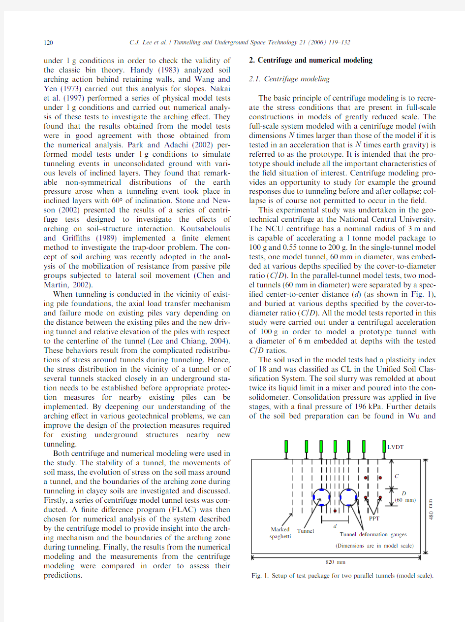
This experimental study was undertaken in the geo-technical centrifuge at the National Central University. The NCU centrifuge has a nominal radius of3m and is capable of accelerating a1tonne model package to 100g and0.55tonne to200g.In the single-tunnel model tests,one model tunnel,60mm in diameter,was embed-ded at various depths speci?ed by the cover-to-diameter ratio(C/D).In the parallel-tunnel model tests,two mod-el tunnels(60mm in diameter)were separated by a spec-i?ed center-to-center distance(d)(as shown in Fig.1), and buried at various depths speci?ed by the cover-to-diameter ratio(C/D).All the model tests reported in this study were carried out under a centrifugal acceleration of100g in order to model a prototype tunnel with a diameter of6m embedded at depths with the tested C/D ratios.
The soil used in the model tests had a plasticity index of18and was classi?ed as CL in the Uni?ed Soil Clas-si?cation System.The soil slurry was remolded at about twice its liquid limit in a mixer and poured into the con-solidometer.Consolidation pressure was applied in?ve stages,with a?nal pressure of196kPa.Further details of the soil bed preparation can be found in Wu and
120 C.J.Lee et al./Tunnelling and Underground Space Technology21(2006)119–132
Lee(2003).The basic properties of the prepared soil bed are listed in Table1.On completion of the consolida-tion,the soil bed,which had an undrained shear strength pro?le of30–40kPa,was lifted and placed in a strong box.The set-up of the test package for the par-allel-tunnel model is shown in Fig.1.Five PPTs were in-serted at selected positions to monitor changes in the pore water pressure.The pore pressure transducer (PPT)was inserted into a pre-drilled hole and then the hole was fully back-?lled with thick slurry.Eight LVDTs were?xed on top of the strong box to record the transverse surface settlements.
The test package was?rst spun at an acceleration of 100g for5min so that any voids generated during the installation of the PPTs and the assembly of the test package might be?lled.After the centrifuge was stopped,one or two60mm diameter model tunnels were cut manually,depending on the test conditions,and then rubber bags were inserted into the tunnels.Tunnel deformation gauges consisting of four thin cantilevers made from stainless steel were installed inside the rubber bags to measure the deformations at the crowns,inverts, and side-walls of the tunnels.The test package shown in Fig.1was prepared for further tunnel collapse tests by connecting air pressure lines to the rubber bags.
The air pressure in the rubber bags was carefully reg-ulated to balance the overburden pressure at the tunnel center during the reacceleration of the model up to a centrifuge acceleration of100g.The tunneling event was simulated by simultaneously reducing the air pres-sure inside the tunnels and eventually down to zero.This air-pressure method of simulating tunnel excavation was adapted from Mair(1979).The air-pressure method was chosen to support the tunnel during the accelerating stages because measuring the tunnel deformation was needed and the waterproo?ng of this measuring device was di?cult if an incompressible heavy?uid-pressure method was used.The method used in the study may cause smaller surface settlements and larger settlement trough widths at the corresponding supporting pressures but no di?erence in the supporting pressure at collapse compared to the incompressible heavy?uid-pressure method.
No more than15min were spent under100g prior to collapse(including the accelerating stage).The dissipa-tion of pore water pressure(or changes of e?ective stress)during these two stages may be less than1%in average.A torvane apparatus was used for determining the undrained shear strength at various depths on the side of the soil bed before and after the test.The test re-sults show that no obvious changes in the undrained shear strengths(less than2kPa)at the same depths were found.Therefore,we assumed that there was minimal migration of pore water pressure and hence that the soil was subjected to undrained shearing.The changes in the pore water pressures,the tunnel deformations,and the surface settlements induced by tunneling were measured continuously.After each model test,the soil bed was cautiously excavated to expose the implanted spaghetti. Further,six undisturbed samples were taken from the soil bed at selected depths for use in uncon?ned com-pression tests.The undrained shear strength(s u)and the secant Young?s modulus(E50),for each soil bed was determined from the average of the results for the six samples,as listed in Table2.
The surrounding soil squeezes into the tunnel as the supporting air pressure is gradually reduced,which?-nally causes tunnel collapse.The overload factor(OF), as de?ned below,is a useful index for describing tunnel stability throughout the entire test process.
OF?
r voàp i
s u
;e1Twhere r vo is the overburden pressure at the tunnel cen-ter,and p i is the supporting pressure.Fig.2shows plots of the surface settlements at the tunnel axis versus OF for the single-tunnel test,Test7(C/D=3),and of those at the symmetrical axis of the settlement trough for the parallel-tunnel test,Twin3(C/D=3,d/D=1.5).This
Table1
Basic properties of the prepared soil bed
Speci?c gravity,G s 2.67 Liquid limit,LL40
Plastic limit,PL22 Plasticity index,PI18
Unit weight,c(kN/m3)18.1 Compression index,C c0.28 Swell index,C r0.0275 Coe?cient of consolidation,C v(cm2/s)0.010524 Permeability,k(m/s) 4.5·10à9Table2
Test con?gurations
Test no.a C/D d/D s u(kPa) Test110.5–31.00 Test120.5–35.12 Test51–36.90 Test81–37.90 Twin41 1.533.00 Twin51 1.539.10 Test32–30.25 Test92–35.79 Twin12348.70 Twin22 1.541.00 Twin92 1.539.52 Twin122235.10 Test63–33.30 Test73–34.00 Twin33 1.536.10 Twin63 1.532.90 Test104–32.17 Twin104 1.534.25 Twin114 1.532.83
a Test3–Test12:single tunnel;Twin1–Twin11:two parallel tunnels.
C.J.Lee et al./Tunnelling and Underground Space Technology21(2006)119–132121
?gure shows that the surface settlements,S,increase dramatically once OF exceeds a critical value.Extending the straight-line portions of the?rst and second parts of the S vs OF curves to intersect at the points shown in Fig.2,the horizontal ordinate of each of these critical points is de?ned as the overload factor at collapse, (OF)c.In engineering practice,the tunnel must be sup-ported against collapse during tunneling.Thus,the load factor(LF)is regarded as the reciprocal of the safety factor
LF?
r voàp i
r voàep iT
c
?
OF
eOFT
c
;e2T
where(p i)c is the measured supporting pressure at col-lapse in the centrifuge model tests.The value of LF var-ies from0to1,which corresponds to variation of the tunnel stability from stable to critical.
A total of19model tests were performed in the study: nine single-tunnel tests and ten parallel-tunnel tests,as listed in Table2.The C/D ratio varied from0.5to4 for the single-tunnel tests,and from1to4for the paral-lel-tunnel tests.The d/D ratios of the parallel-tunnel tests were1.5,2,and3for C/D=2,and the d/D ratio was1.5for the other C/D ratios.
2.2.Numerical modeling
The numerical‘‘experiments’’were carried out with a two-dimensional explicit?nite di?erence program,FLAC2D(Cundall et al.,1993).A plane-strain model with large-strain formulation was used to simulate the deformation behavior of the ground surrounding un-lined tunneling.In order to compare the results of the numerical and centrifuge modeling,the boundary condi-tions and soil properties used in the numerical model were chosen to be the same as those studied in the cen-trifuge model tests.The numerical analysis considered a mesh with a width of82m and a height of48m as shown in Fig.3,which are the exact dimensions of the soil bed used in the centrifuge model tests.The left and right boundaries were?xed in the x-direction,and the bottom boundary was?xed in the x-and y-directions.The grid size around the tunnels was 0.5m·0.5m in the prototype and was enlarged by a factor of1.08as the distance to tunnel center increases. The soil bed was treated as an isotropic and elastic per-fectly plastic continuum following the Mohr–Coulomb failure criterion(/=0).A total of six numerical models were analyzed.The model conditions and the mechani-cal properties of soil bed measured from the uncon?ned compression tests used in the numerical analysis are shown in Table3.
The numerical modeling was commenced at a state of geostatic equilibrium,and allowed to come to numerical equilibrium under the force of gravity.This step pro-vides an estimate of the in situ stress in the soil prior
Fig.3.Geometry used in the numerical analysis(C/D=3,d/D=1.5). Table3
Geometric conditions and mechanical properties of the numerical models
Test no.C/D d/D s u(kPa)E50(kPa)c(kN/m3)m Ntest81–37.90350018.10.49 Ntwin41 1.533.00350018.10.49 Ntest92–35.79350018.10.49 Ntwin22 1.541.00400018.10.49 Ntest73–34.00350018.10.49 Ntwin33 1.536.10350018.10.49 122 C.J.Lee et al./Tunnelling and Underground Space Technology21(2006)119–132
to tunneling.Secondly,the elements representing the excavated soil in the tunnel were nulled and a uniform supporting pressure equal to the overburden pressure at the center of tunnel was applied to the interior bound-ary of the circular opening to keep the tunnel stable.The supporting pressure was then reduced by a decrement of 10kPa per step in order to simulate the decrease in the supporting pressure that was applied in the centrifuge model tests.
For FLAC,the value of maximum nodal unbalance force is used to determine if a simulation having reached equilibrium.In the current study,an equilibrium state was regarded as having converged when the maximum unbalance force of every node in the mesh was less than 10N(the ratio of the maximum unbalance force to the overburden pressure on the element was about0.005%) in the simulation of per step.The simulation was then moved to the next step(reducing the supporting pres-sure by a decrement of10kPa in the study).The sup-porting pressure was reduced further until an error message indicating bad geometry of mesh appeared. The message of the bad geometry of mesh implies a dra-matic increase in the displacement within the mesh, therefore,the supporting pressure at this step is de?ned as the collapse supporting pressure,(p num)c,which is determined from the numerical modeling.By substitut-ing(p num)c into Eqs.(1)and(2),the overload factor, (OF num)c,at collapse and the load factor(LF)num, respectively,can be determined.The relationship be-tween the overload factor and the maximum surface set-tlement obtained from the centrifuge modeling and that computed with the numerical modeling for the single-tunnel and parallel-tunnel models are in good agreement before tunnel collapse,as shown in Fig.4.
Numerical modeling can be used to examine defor-mation more precisely at small strain levels and at more locations than can be achieved with centrifuge modeling, but is not as precise as the measurements of the failure and post-failure behavior that the centrifuge modeling can provide.Therefore,integrating and comparing the results derived from the numerical and centrifuge mod-els provides improved understanding of the deformation behavior and the arching mechanism during tunneling.
https://www.360docs.net/doc/7013361648.html,parison of the results from centrifuge and numerical modeling
3.1.Tunnel stability
The tunneling event was simulated by reducing the supporting pressure inside the tunnels in both the centri-fuge modeling and the numerical experiments.Fig.5 shows the relations between the C/D ratio and(OF)c measured in the single-tunnel and the parallel-tunnel model tests(solid symbols),and the values of(OF num)c calculated from the numerical modeling(hollow sym-bols).The relationships between the C/D ratio and the lower bound of the overload factor,(OF)L,for single-tunnel(Lee et al.,1999),and the upper bound of over-load factor,(OF)L for single-tunnel and parallel tunnels (Wu and Lee,2003),are also displayed in Fig.5.The test results from Mair(1979)are also included in this?g-ure.The increase in(OF)c with the C/D ratio illustrates that the stability of the tunnel improves if the tunnel is embedded more deeply.In addition,Fig.5also shows that the stability of parallel-tunnel is worse than that of single tunnel;lower overload factors at collapse were found in the parallel-tunnel model.
The overload factors at collapse(solid symbols)ob-tained from the centrifuge model for both the single-tun-nel and parallel-tunnel models have nearly the same values as those derived from the corresponding numeri-cal model(hollow symbols),as shown in Fig.5.The val-ues of(OF)c and(OF num)c for the single-tunnel model are all con?ned by upper and lower bounds.The values of(OF)c and(OF num)c for the parallel-tunnel model are
C.J.Lee et al./Tunnelling and Underground Space Technology21(2006)119–132123
also con?ned by the upper bound,but no lower bound solution has yet been derived.The centrifuge and numerical modeling provide consistent evaluations of the tunnel stability.
3.2.Surface settlement troughs
Figs.6and7compare the computed(represented by lines)and measured surface settlement troughs (represented by symbols)at selected load factors for the single-tunnel model(C/D=2)and for the paral-lel-tunnel model(C/D=1,d/D=1.5),respectively. The distances,X,o?set from the tunnel center-line (or from the center-line of the two tunnels in the par-allel-tunnel tests)and the surface settlements,S,are both normalized with respect to the tunnel diameter, D.The computed settlement troughs compare reason-ably well both in shape and magnitude with those measured in the centrifuge models at the correspond-ing load factors.The shape of the settlement trough for the single tunnel approximates closely to that of the error function.An empirical approach derived from centrifuge modeling has been proposed for calcu-lating the surface and subsurface settlement troughs for various ground losses due to tunneling in soft clay and in sandy soils(Wu and Lee,2003;Lee et al., 2004).In addition,these researchers proposed a super-imposition method for estimating the surface settle-ment troughs caused by parallel tunneling from the parameters obtained for single tunneling.Their meth-odology for predicting the settlement troughs based on the ground loss was veri?ed by comparison with12 sets of monitored?eld data(Wu and Lee,2003).
https://www.360docs.net/doc/7013361648.html,parison of the excess pore water pressures obtained from centrifuge and numerical modeling In an undrained system,the stress changes (D r1,D r2,D r3)due to tunneling would generate excess pore water pressure within the soil mass.With the ap-proach suggested by Henkel,the changes in the pore water pressure,D u,can be determined with the equation
D u?
1
3
eD r1tD r2tD r3Tta?eD r1àD r2T2
teD r2àD r3T2teD r3àD r1T2 1=2;e3Twhere a is Henkel?s pore water pressure parameter,and D r1,D r2,D r3are the changes in the major,intermediate, and minor principle stresses,respectively.A comparison of a and Skempton?s parameter,A,derived from triaxial compression tests gives
a?
1
???
2
p Aà
1
3
.e4T
This de?nition is useful because it enables the predic-tion of the D u associated with loading conditions un-der plane strain conditions if we assume that the soil bed is an isotropic and elastic-plastic material.By using a value of a of0.3(determined from the triaxial compression tests)and D r2=1/2(D r1+D r3)for the plane strain and undrained conditions,the developed excess pore water pressure can be estimated after the changes in total stress are calculated in the numerical simulations.
In the centrifuge modeling,the stress changes on a soil element during tunneling cannot be measured, whereas the changes of pore water pressure can be di-rectly measured.The numerical analysis in terms of total stress approach can give the changes of total stress but it cannot give the changes of pore water pressure.How-ever,the changes of pore water pressure can be esti-mated using Eq.(3)after the total stress changes were obtained from the numerical analysis.In this study, the excess pore water pressure ratio,(D u/r vo),de?ned
124 C.J.Lee et al./Tunnelling and Underground Space Technology21(2006)119–132
as the excess pore water pressure normalized with the to-tal overburden pressure of the measured point,is used to follow the variations of the excess pore water pressure during the tunneling simulations.The method for com-parison of the measured and calculated(D u/r vo)is de-scribed as follows.
The e?ects of tunneling on the total stress within the soil mass around a tunnel can be estimated from the computed responses at the grids of points shown in Fig.8(a)(Test7,C/D=3),Fig.8(b)(Test9,C/D=2), and Fig.8(c)(Test8,C/D=1)for the single-tunnel tests and from those shown in Figs.9(a)(Twin3;C/D=3, d/D=1.5)and9(b)(Twin2;C/D=2,d/D=1.5)for the parallel-tunnel tests.In the centrifuge model,the pore water pressures were measured at the points repre-sented by solid circle symbols in Figs.8and9(i.e.,A0, A3,B1,C1,and C3in Fig.8(a);A0,B2,C1,D1,and D2 in Fig.8(a)).
Figs.10and11compare the variations in the mea-sured(represented by lines)and computed(repre-sented by hollow circle symbols)D u/r vo with the overload factor at the corresponding locations for Test7(C/D=3)and for Twin3(C/D=3.d/D=1.5), respectively.There is very reasonable agreement be-tween the measured and computed excess pore water pressures before tunnel collapse.The small discrep-ancy between them may result from pore water pres-sure dissipation caused by partial drainage due to the appearance of micro-cracks around the small holes into which the pore water pressure transducers were inserted.Results of similar consistency were also found in the tests with di?erent C/D and d/D ratios. Thus the stress states computed from the numerical experiments can be and are used to investigate the arching behavior of the soil mass around the tunnel in the next section,although the stress measurements in the centrifuge model tests were impossible.
C.J.Lee et al./Tunnelling and Underground Space Technology21(2006)119–132125
4.Mechanism of arching around tunnels
4.1.Evolution of arching e?ect
The e?ects of tunneling on the total stress within the soil mass around a tunnel can be estimated from the computed responses at the grids of points shown in Fig.8(a)(Test7,C/D=3),Fig.8(b)(Test9,C/D=2), and Fig.8(c)(Test8,C/D=1)for the single-tunnel tests and from those shown in Figs.9(a)(Twin3;C/D=3, d/D=1.5)and9(b)(Twin2;C/D=2,d/D=1.5)for the parallel-tunnel tests.A more detailed understanding of the stress transfer in a tunneling problem from moving parts of the soil(settle more)to adjacent parts (settle less)can be achieved by considering the vertical stress redistributions in the soil mass above the spring line.The arching ratio is de?ned as ARe%T?
D r v
r vo
?100;e5T
where D r v is the change in the vertical stress during tun-neling and r vo is the total overburden pressure.In this study,we used the arching ratio to describe the arching behavior quantitatively at various locations.
An element that receives higher load transfers from adjoining yielding or?exible elements will generate a larger positive arching ratio.Conversely,a negative arching ratio will arise if an element shifts load to non-yielding parts or to more rigid elements.Fig.12 shows a plot of the arching ratio versus overload factor for NTest7(C/D=3)at the grid of points shown in Fig.8(a).As the overload factor increases,all of the ele-ments on the vertical center-line(Line A)experience a decrease in vertical stress(negative AR)but the elements
126 C.J.Lee et al./Tunnelling and Underground Space Technology21(2006)119–132
on the spring line(B1–E1)experience an increase in ver-tical stress(positive AR),as shown in Fig.12(a).Simi-larly,as can be seen in Fig.12(b)and(c),the magnitude of the arching ratio is also related to the dis-tance o?set from the tunnel center and to the overload factor(comparing the arching ratios on Lines A,B,C, D,and E).Fig.13summarizes the changes in the arching ratio for three overload factors(OF=1,3,and (OF num)c)for the elements on Lines A to E for NTest7 (C/D=3).The magnitude of the positive arching ratio increases with increases in the overload factor for the elements along Line B but declines rapidly once the ele-ment is yielding(Fig.13(b)).The element at C1experi-ences the largest positive arching ratio(about a9% rise).The elements located at a greater distance from the tunnel center experience smaller positive arching ratios.In contrast,the arching ratio becomes more neg-ative as the overload factor increases for the elements on Line A(Fig.13(a)).
Similarly,Fig.14summarizes the arching ratio as a function of the overload factor for the elements on the spring line(B1–E1)and on the vertical center-line (A2–A3)shown in Fig.8(b)for NTest9(C/D=2). Fig.15summarizes the arching ratio as a function of the overload factor for the elements on the spring line(B1–D1)and on the vertical center-line(A2) shown in Fig.8(c)for NTest8(C/D=1).The evolu-tion of the arching ratio in the shallower tunneling shown in these two?gures is similar to those pre-sented in Figs.12and13but smaller positive and neg-ative arching ratios are obtained at the corresponding points for deeper tunneling(NTest7,C/D=3).Shal-lower tunneling imposes a larger arching e?ect on the surrounding soil mass.
C.J.Lee et al./Tunnelling and Underground Space Technology21(2006)119–132127
Fig.16summarizes the changes in the arching ratio for the elements on Lines A–F(Fig.9(a))for three over-load factors(OF=1.5,2.5,and(OF num)c)for NTwin3(C/D=3,d/D=1.5).Fig.17shows the changes in the arching ratio for the elements on Lines A–F(Fig.9(b)) for NTwin2(C/D=2,d/D=1.5).A comparison of the changes in the arching ratios shown in Figs.13 and16indicates that the arching ratios in parallel tun-neling evolve in nearly the same way as in single tunnel-ing,except at Element A1,which is located on Line A and on the spring line.At this point,a larger positive arching ratio develops initially,but its value rapidly de-clines to near zero once the stress state becomes yielding, in the same manner as the other elements(Fig.16(a)). This part of the soil mass takes the load that is trans-ferred from the two compressive arches above the tun-nels due to parallel tunneling,and behaves like a pillar.After examining in detail the changes in the arch-ing ratio shown in Figs.13–15for the single-tunnel tests and in Figs.16and17for the parallel-tunnel tests,we reached the same conclusion for parallel tunneling as obtained for single tunneling,namely that shallower tunneling imposes a larger arching e?ect on the sur-rounding soil mass because of the higher arching ratio.
In the centrifuge modeling,the excess pore water pressure ratio will increase on an element in the soil bed that receives load transfers from adjoining yielding or?exible elements.Conversely,the excess pore water pressure ratio will decrease if an element shifts load to non-yielding parts or to more rigid elements.Therefore, the changes in the measured excess pore water pressure ratio can also be used to track the load transfers among the elements during tunneling simulation in the centri-fuge modeling.For example,the excess pore water pres-sure ratios shown in Figs.14and15initially rise with increases in the overload factor,but later fall as the ele-ments in non-yielding states progress to yielding states during increases in the overload factor.
4.2.Boundaries of the arching and plastic zones in the tunnel collapse stage
As discussed in the previous section,the outer bound-aries of the arching and plastic zones expand outward from the excavated area as the overload factor increases. Knowledge of the boundaries of the arching and plastic zones in the tunnel collapse stage is thus crucial for engi-neering practice,and is now discussed.
Fig.18presents the variations in the shear stress ra-tio,q/s u,at(OF num)c for the soil elements on the selected lines at the elevations of3.5,7.29,11,and16m above the spring line(NTest7,C/D=3).Here q= 1/2(r1àr3).The arrows shown in Fig.18indicate the positions of the outermost boundary of the plastic zone at the elevations where the elements have stress states of s u/q=1and are regarded as yielding.As can be seen in the?gure,the plastic boundaries extend from the tunnel center-line as far as12m along the spring line(about twice the tunnel diameter)and but only to10m at an
128 C.J.Lee et al./Tunnelling and Underground Space Technology21(2006)119–132
elevation3.5m above the spring line.Therefore,the out-er boundary of the plastic zone in the tunnel collapse stage can be inferred by examining all the elements re-garded as yielding(not just those considered in Fig.18),and is depicted in Fig.8(a)as a thick line of dashes.Fig.8(b)and(c)also display the outer bound-aries of the plastic zone for the single-tunnel models (C/D=1,2).
Similarly,Fig.19presents the variations of the shear stress ratio,q/s u,at(OF num)c for the soil elements on the
C.J.Lee et al./Tunnelling and Underground Space Technology21(2006)119–132129
selected lines at elevations of3.5,7.29,11and16m above the spring line(NTwin3,C/D=3,d/D=1.5). As can be seen in the?gure,the boundaries of the plastic zone extend from the center-line of the two tunnels as far as15m along the spring line and8m at an elevation of3.5m above the spring line.The outer boundary can also be determined with the procedure described in the previous paragraph,as shown in Figs.9(a)(Twin3) and9(b)(Twin2)(thick lines of dashes).
The non-yielding elements in the arching zone receive a load transfer from the elements in the plastic zone.The area lying between the outer boundary of the plastic zone and the boundary at which the elements have an arching ratio larger than1%is regarded as the arching zone.Thus the outer boundaries of the single-tunneling arching zones can easily be determined,and are shown as thick lines in Fig.8(a)–(c)for various C/D ratios.
The arching mechanism in the case of two parallel-tunnels is similar to that for a single-tunnel,so the same procedure can be used to infer the boundaries of the arching zone.They are depicted in Fig.9(a)and(b) for Twin3and Twin2.
Tunneling at di?erent burial depths can result in arching and plastic zones of di?erent extents.Deep sin-gle tunneling will result in a wider arching zone,but two parallel tunnels only generate a slightly wider arching zone for the same burial depth.The extents of the arch-ing zones for a single-tunnel and parallel-tunnels embed-ded at various depths(C/D=1,2,3)are shown in Fig.20(a)and(b),respectively.The curves representing the outer bounds of the arching zones were obtained as follows:
z?0.1exp0.305xà0.045
C
D
x
for singleàtunnel;e6aTz?0.105exp0.27xà0.0375
C
D
x
for two parallelàtunnelsed=D?1.5T;e6bTin which x is the distance o?set from the tunnel center for the single-tunnel and the distance o?set from the center-line of the two parallel-tunnels,and z is the depth.
4.3.Positive and negative arching zones
After examining the variations in the arching ratios of the elements surrounding the tunnel(or tunnels),as shown in Figs.13,16,and17,it was found that each arching zone can be divided into two zones,the positive
130 C.J.Lee et al./Tunnelling and Underground Space Technology21(2006)119–132
arching zone(with positive AR)and the negative arch-
ing zone(with negative AR).The boundaries(dash–dot lines)of the two zones derived from the numerical analysis are shown in Fig.8(a)–(c)for the single-tunnel with various C/D ratios and in Fig.9(a)and(b)for two parallel-tunnels with C/D=2,3and d/D=1.5. The shaded rectangular regions in these?gures corre-spond to the half-width of the sliding wedge,which can be determined from the upper bound solution using the collapse mechanism proposed by Wu and Lee (2003).The sliding wedges are reasonably consistent with the boundaries of the negative arching zones.A pile embedded in the negative arching zone would partially lose both end bearing capacity and skin friction on the pile body due to the reduction of the vertical stresses
C.J.Lee et al./Tunnelling and Underground Space Technology21(2006)119–132131
and would experience a large amount of settlement dur-ing new nearby tunneling.
5.Summaries and conclusions
A series of centrifuge model tests were carried out to investigate the surface settlement trough,excess pore water pressure generation,and tunnel stability of the tunnels with various C/D ratios(single-tunnel)and d/ D ratios(two parallel-tunnels).Numerical analysis was also conducted to evaluate the tunnel stability and arch-ing e?ects that develop during tunneling in soft clayey soil.The centrifuge and numerical modeling produced consistent results in their predictions of the surface set-tlement trough,excess pore water generation,and the overload factors at collapse for both single tunneling and parallel tunneling.An arching ratio derived from the numerical analysis was de?ned to describe the evolu-tion of the arching e?ect in the soil mass surrounding the tunnels.The boundaries of the arching zones for both single tunneling and parallel tunneling were determined. In addition,the boundaries of the positive and negative arching zones were also proposed.Construction engi-neers can easily locate the boundaries of the positive and negative arching zones and then take appropriate measures to mitigate possible damages to underground structures due to new nearby tunneling. Acknowledgments
The?nancial support provided by the National Science Council,Taiwan,under Grants NSC87-2211-E-008-024 and NSC91-2211-E-008-026is gratefully acknowledged. References
Clough,G.W.,Schmidt, B.,1981.Design and performance of excavation and tunnels in soft clay.In:Soft Clay Engineering.
Elsevier,Amsterdam,pp.600–634(Chapter8).Chen,C.Y.,Martin,G.R.,2002.Soil–structure interaction for landslide stabilizing https://www.360docs.net/doc/7013361648.html,puter and Geotechnics29(5),363–386. Cundall,P.A.,Coetzee,M.J.,Hart,R.D.,Varona,P.M.,1993.FLAC User?s Manual.Itasca Consulting Group,USA.
Handy,R.L.,1983.The arch in soil arching.Journal of Geotechnical Engineering,ASCE111(3),302–318.
Koutsabeloulis,N.C.,Gri?ths,D.V.,1989.Numerical modeling of the trap door problem.Geotechnique39(1),77–89.
Ladanyi,B.,Hoyaux,B.,1969.A study of the trap-door problem in a granular mass.Canadian Geotechnical Journal6(1),1–11. Lee,C.J.,Wu,B.R.,Chiou,S.Y.,1999.Soil movements around a tunnel in soft soils.Proceedings of the National Science Council, Part A:Physical Science and Engineering23(2),235–247.
Lee,C.J.,Chiang,K.H.,2004.Load transfer on single pile near new tunneling in sandy ground.In:Matsui,Tanaka,Mimura(Eds), Proceedings of the International Symposium on Engineering Practice and Performance of Soft Deposits(IS-OSAKA2004), pp.495–506.
Lee,C.J.,Chiang,K.H.,Kou,C.M.,2004.Ground movement and tunnel stability when tunneling in sandy ground.Journal of the Chinese Institute of Engineers27(7),1021–1032.
Lee,K.M.,Rowe,R.K.,1991.An analysis of three-dimensional ground movements:the thunder bay tunnel.Canadian Geotechni-cal Journal28(1),25–41.
Mair,R.J.,1979.Centrifugal modeling of tunnel construction in soft clay.Ph.D Thesis,University of Cambridge,UK.
Mair,R.J.,Gunn,M.J.,O?Reilly,M.P.,1981.Ground movements around shallow tunnels in soft clay.In:Proceedings of the10th International Conference on Soil Mechanics and Foundation Engineering,pp.323–328.
Nakai,T.,Xu,L.,Yamazaki,H.,1997.3D and2D model tests and numerical analyses of settlements and earth pressures due to tunnel excavation.Soils and Foundations37(3),31–41.
Park,S.H.,Adachi,T.,https://www.360docs.net/doc/7013361648.html,boratory model tests and FE analyses on tunneling in the unconsolidated ground with inclined layers.
Tunneling and Underground Space Technology17,181–193. Peck,R.B.,1969.Deep excavation and tunneling in soft ground.In: Proceedings of7th International Conference on Soil Mechanics and Foundation Engineering,Mexico,State of the Art Volume,pp.
225–290.
Stone,K.J.L.,Newson,T.A.,2002.Arching e?ects in soil–structure interaction.In:Phillips,Guo,Popescu(Eds.),Physical Modeling in Geotechnics:ICPMG?02,pp.935–939.
Terzaghi,K.,1943.Theoretical Soil Mechanics.Wiley,New York. Wang,W.L.,Yen,B.C.,1973.Soil arching in slopes.Journal of the Geotechnical Engineering,ASCE100(1),61–78.
Wu,B.R.,Lee,C.J.,2003.Ground movements and collapse mecha-nisms induced by tunneling in clayey soil.International Journal of Physical Modelling in Geotechnics3(4),13–27.
132 C.J.Lee et al./Tunnelling and Underground Space Technology21(2006)119–132
2017山香教育理论基础整理笔记(教育学、心理学、教育心理学)
第一章教育与教育学 1、《学记》——“教也者,长善而救其失者也” 2、战国时荀子——“以善人者谓之教” 3、许慎在《说文解字》中认为“教,上所施,下所效也。”“育,养子使作善也。” 4、最早将“教育”一词连用的则是战国时期的孟子:“得天下英才而教育之,三乐也。” 5、分析教育哲学的代表人物谢弗勒在《教育的语言》中把教育定义区分为三种: 规定性定义:作者自己认为的定义,即不管他人使用的“教育”的定义是什么,我认为“教育”就是这个意思。运用规定性定义虽然有一定的自由度,但是,要求作业在后面的论述和讨论中,前后一贯地遵守自己的规定。 描述性定义:回答“教育实际上是什么”的定义。尽量不夹杂自己的主观看法,适当地对术语或者使用该术语的方法进行界定。 纲领性定义:回答“教育应该是什么”的定义。即通过明确或隐含的方式告诉人们教育应该是什么或者教育应该怎么样。 6、教育是一种活动。“教育”是以一种“事”的状态存在,而不是以一种“物”的状态出现。因而。我们就把“活动”作为界定教育的起点。 7、教育活动是人类社会独有的活动。 8、“生物起源论”代表人物: 利托尔诺在《各人种的教育演变》中指出教育是超出人类社会以外的,在动物界中就存在的。 沛西·能在《教育原理》中也认为教育是一个生物学过程,扎根于本能的不可避免的行为。 9、“终身教育”概念的提出,指明人在生理成熟后仍继续接受教育。 10、社会性是人的教育活动与动物所谓“教育”活动的本质区别。 11、教育的本质:教育活动是培养人的社会实践活动。 12、教育是人类通过有意识地影响人的身心发展从而影响自身发展的社会实践活动。 13、学校教育是一种专门的培养人的社会实践活动。 14、学校教育自出现以来就一直处于教育活动的核心。 15、学校教育是由专业人员承担的,在专门机构——学校中进行的目的明确、组织严密、系统完善、计划性强的以影响学生身心发展为直接目标的社会实践活动。 16、学校教育的特征:①可控性②专门性③稳定性 17、教育概念的扩展——大教育观的形成 18、1965年,法国教育家保罗·朗格朗在《终身教育引论》中指出,教科文组织应赞同“终身教育”的原则。 19、1972年,埃德加·富尔在《学会生存》中对“终身教育”加以确定,并提出未来社会是“学习化社会”。 20、“终身教育”概念以“生活、终身、教育”三个基本术语为基础。 从时间上看,终身教育要求保证每个人“从摇篮到坟墓”的一生连续性的教育过程; 从空间上看,终身教育要求利用学校、家庭、社会机构等一切可用于教育和学习的场所; 从方式上看,终身教育要求灵活运用集体教育、个别教育、面授或远距离教育; 从教育性质上看,终身教育即要求有正规的教育与训练,也要求有非正规的学习和提高,既要求人人当先生,也要求人人当学生。 21、教育的形态,是指教育的存在特征或组织形式。 22、在教育发展史上,教育的形态经历了从非形式化到形式化,再到制度化教育的演变。
用友财务软件说明书
用友财务 用友财务软件说明书 关于用友软件操作的有关注意事项如下: 1、第一次运行时没有系统管理员密码(密码为空),用户最好在第一次运行时就改入新的密码,以防疏漏。 2、作为第一次运行,以下步骤必不可少:设置操作员、建立帐套、分配操作员权限这项工作必须在运行客户端子系统之前进行,否则由于不存在可用的帐套,客户端会登录失败(除非是登录演示帐套999)。 3、首先要将登录到系统管理中的各项功能和任务退出,然后退出各子系统。只有退出UFERP-M系统后才能关机,否则将造成数据丢失。 4、还应注意凭证的审核和记帐应该分工行使,系统也做了智能化的考虑。 第一节、系统安装、启动、财务管理 (一)安装: 使用用友财务系统软件安装总帐系统和UFO报表系统。(这里只介绍这两个系统,其它的待以后在做详细说明)。 (二)启动: 按照以下程序进入并启动系统: 用友——系统服务——系统管理——系统——注册。具体如图1.1和1.2所示。 (图1.1) (图1.2) 注意:图1.1的密码不用输,直接进入。 (三)建立帐套:
1、按照系统管理——帐套——建立,就会见到以下图示。(如下图,1.3——1.6)。在这几张图中详细介绍了关于建立帐套的步骤。 按照上图输入信息,如果完成请按下一步按扭。然后,见(图1.4) 上述空白处最好完全填写,填完信息后继续下一步,入下图(1.5)所示 次项内容最好照实际情况填写,为了以后备查。
在这里最好点击‘按行业性质预置科目’选择框。然后,继续下一步操作。如(图1.6) 接着,会出现可创建帐套了的对话框,选择‘是’即可。出现(图1.7)。这时,你可以根据公司的大小选择存货的详细程度及级别(如供货方的情况、部门情况、地区情况等)但最好也是不应改动。
新中大财务软件使用说明
新中大财务软件使用说明 第一部分:核算单位管理 1、双击桌面上的“新中大软件”图标,打开后双击其中的“核算单位”运行 “核算单位管理模块”。 2、首先系统要求输入系统管理员口令。首次运行时的缺省口令为12345。建议 你进入系统后即行更改系统管理员的密码,以确保数据的安全。 3、密码输入正确后,按回车键或用鼠标点击“确认”,即可进行具体的操作。 4、新增帐套步骤:帐套功能——新建帐套——存入 在参数中,帐套号、单位名称、行业(选择企业会计制度)、单位负责人、财务主管、建账日期及模块选择(账务处理系统、报表处理系统)这几项是必须要填的,其余则可视情况填写。 此外,在以上的参数中,帐套号,行业,建账日期这几项是不允许直接修改的。 “建账日期”是指计算机正式记账的月份。假如当前月份是2005年3月份,而又想从本年的1月份开始做账,则“建账日期”处输入的是2005年1月1日。“建账日期”还将影响账务时科目余额的输入:如某单位的建账日期为2005年1月1日,初始化时应录入2004年底的余额;如某单位的建账日期为2005年7月1日,则初始化时应录入2005年6月底的余额和1至6月的借贷方累计发生数。 5、修改帐套信息:帐套功能——修改帐套信息——确认 (1)只能进行局部的修改,并不是所有的项目都可以修改的,如帐套号、行业性质、建账日期等是不允许修改的,如果要对这些选项进行修改,则必须把此帐套删除,然后重新增加帐套。 (2)“财务主管”名称的修改,只能针对以后的年度有效,对于以前年度和当前年度,财务主管是不允许修改的。 (3)其他的内容可以自由修改。 6、删除帐套:帐套功能——删除帐套——是 删除帐套后的数据是无法恢复的,因此,对帐套删除操作千万慎重。
用友财务软件使用说明书范文
用友财务软件使用 说明书
用友财务软件使用教程(一) 第一节系统管理 企业级会计信息系统与传统的会计信息系统有着根本的不同,它由三大系列、十几个子系统构成,各个子系统为同一个主体的不同需要服务,本身具有相对独立的功能,但彼此之间又具有紧密的联系.它们共用一个数据库,具有公共的基础信息,拥有相同的账套和年度账。只有这样,才能达到数据共享,最终实现财务、业务一体化的管理。 一、系统管理的主要功能 系统管理模块主要功能是对系统的各个子系统进行统一的操作管理和数据维护,具体包括以下几个方面: 1. 账套管理 账套指的是一组相互关联的数据。一般来说,能够为企业中每一个独立核算的单位建立一个账套,系统最多能够建立999套账。 账套管理包括账套的建立、修改、引入、输出等。 2. 年度账管理 在企业级会计信息系统中,用户不但能够建立多个账套,而且每个账套中还能够放不同年度的会计数据。这样,对不同核算单位、不同时期的数据只需要设置相应的系统路径,就能够方便地进行操作。 年度账管理包括年度账的建立、清空、引入、输出和结转上年数据。 3. 操作权限的集中管理以及安全机制的统一设立 为了保证系统及数据的安全与保密.系统管理提供了操作员及操作权限的集中管理能。经过对系统操作分工和权限的管理一方面能够避免与业务无关的人员进入系统,另一方面能够对系统所含的各个子产品的操作进行协调以保证各负其责,流程流畅。操作权限的集中包括设定系统各模块的操作管理员以及为操作员分配一定的权限。设立统一的安全机制包括数据库的备份、功能表及上机日志。 二、系统启用的及基本流程 1. 新用户操作流程 三、启动系统管理 启动系统管理将涉及到具体操作过程,下面以用友财务及企管软件UFERP-
教育学教育心理学理论及代表人物
教育学有关理论、代表人物 1、神话起源说—— 2、生物起源说——利托尔诺(法国) 3、心理起源说——孟禄(美国) 4、劳动起源说——马克思(前苏联) 5、中国史上第一部教育文献——《学记》——乐正克 6、西方较早讨论教育问题的着作——《论演说家的培养》(《雄辩术原理》)——昆体良(古罗马) 7、非制度化教育思潮——库姆斯、伊里奇 8、雄辩与问答法——苏格拉底(古希腊) 9、《理想国》——柏拉图(古希腊) 10、《政治学》——亚里士多德(古希腊) 11、教育学作为一门独立学科的萌芽——《大教学论》——夸美纽斯(捷克) 班级授课制,泛智教育。 12、首次提出把教育学作为一门独立的学科——培根(英国) 13、自然主义教育——《爱弥儿》——卢梭(法国) 14、教育学进入大学讲坛——康德(德国)、《林哈德与葛笃德》——裴斯泰洛齐(瑞士)
15、科学教育思潮的兴起,课程体系——《教育论》——斯宾塞(英国) 16、实验教育学——梅伊曼、拉伊(德国) 17、发展性教学理论——《教育与发展》——赞科夫(前苏联) 高难度进行教学的原则、高速度进行教学的原则、理论知识主导作用原则(重理性原则)、理解学习过程原则、对差等生要下功夫的原则 18、范例教学——瓦.根舍因(德国) 19、和谐教育思想——苏霍姆林斯基(前苏联) 20、《教育漫话》——洛克(英国) “白板说”、绅士教育、国民教育思想与民主教育思想。 22、规范教育学的建立——《普通教育学》——赫尔巴特(德国) 传统教育学代表、教师中心,教材中心,课堂中心、四段教学法、统觉观念。 23、实用主义教育学——《民本主义与教育》——杜威(美国) 现代教育学代表、教育即生长,教育即生活,教育即经验的改造或重组、在做中学、儿童中心主义。 24、第一部马克思主义的教育学着作——《教育学》——凯洛夫(前苏联) 25、我国第一部马克思主义的教育学着作——《新教育大纲》——杨贤江 26、设计教学法——克伯屈(美国)
金蝶财务软件使用说明书
一、使用前准备工作 一、安装前的准备工作 1、首先,建立个名为“备份”的文件夹(将来备份用)。 打开我的电脑→双击D盘或其他非系统盘→ 新建“金蝶软件” 目录→双击“金蝶软件”目录→单击右键“新建”→ 文件夹→ 系统生成一个新文件夹,输入文件夹的名字“备份”。 2、然后,同样的方法建立一个专门存放账套的文件夹。 二、快速入门 (一)、窗口说明; 1、标题栏:显示窗口名称。 2、控制菜单:常用命令,使窗口放大、缩小、关闭。 3、菜单条:包含窗口所有特定的命令,如…文件?。 (二)、鼠标操作: 1、单击:按下鼠标按键,立即放开。一般用于定位或选择做某个对象。 2、双击:快速地按两次鼠标按键。一般用于执行某个动作。 3、拖动:按下鼠标按键保持不放,然后移动,可将某个对象拖到指定位置。 4、指向:移动鼠标,使屏幕上的鼠标指针指向选择的项目。 注:如不特别声明,有关鼠标的操作均使用鼠标左键。 (三)、常用命令按钮 1、[增加]按钮:单击此按钮增加资料。 2、[修改]按钮:选中要修改的资料后单击此按钮修改资料。 3、[删除]按钮;选中资料后单击此按钮删除选中的资料。 4、[关闭]按钮:关闭当前窗口,返回上一级窗口。 5、[确认]按钮:确认输入有效。 6、[取消]按钮:输入无效,或取消某个操作。 (四)、菜单功能简介 文件菜单____ 对帐套操作的各种功能按钮。 功能菜单____ 系统各模块的启动按钮。 基础资料---- 系统基本资料设置 工具菜单____ 用于用户的授权、口令的更改、现金流量表工具等。 窗口---- 用于对软件的窗口布局的改变 帮助菜单____ 系统的在线帮助、常见问题、版本的查询。 三、软件的安装 1、硬加密软件的安装 关闭计算机→将加密卡插入计算机后的打印机接口上→ 将打印机电缆接在加密卡上→ 打开计算机,启动系统→将安装光盘放入光驱内→单击“金蝶KIS标准版”→根据系统提示进行操作→安装完毕→重新启动计算机。 2、软加密软件的安装
教育心理学理论
教育心理学理论 一、学习分类理论 1、加涅 (1)学习八水平分类 按学习水平简繁程度分为:①信号学习;②刺激—反应学习;③连锁反应;④言语联想学习;⑤辨别学习;⑥概念学习;⑦规则学习;⑧解决问题学习 (2)学习六水平分类 ①连锁学习;②辨别学习;③具体概念学习;④定义概念学习;⑤规则学习;⑥解决问题学校 (3)学习结果分类 ①言语信息的学习;②智慧技能的学习;③认知策略的学习;④态度的学习;⑤运动技能的学习 2、奥苏贝尔学习性质分类(两个维度互不依赖、相互独立) (1)根据学习的方式:接受学习、发现学习 (2)根据学习材料与学习者原有知识结构的关系:有意义学习、机械学习 3、我国学习结果的分类 ①知识学习;②技能学习;③道德品质或行为习惯的学习 二、学习理论 1、联结理论 (1)经典条件反应论 ①巴甫洛夫:学习就是形成刺激与反应之间的联系 一级条件反射、二级条件反射 动力定型:大脑皮层对刺激的定型系统所形成的反应定型系统 外抑制、超限抑制、消退、泛化、分化 正诱导:一个部位发生抑制引起周围发生兴奋地过程。 负诱导:一个部位发生兴奋引起周围发生抑制的过程。 同时诱导、继时诱导 第一信号系统:能够引起条件反应的物理性的条件刺激。 第二信号系统:能够引起条件反应的以语言符号为中介的条件刺激。 ②华生:通过建立条件作用,形成刺激与反应间的联结的过程。遵循频因律、 近因律。(学习的实质在于形成习惯) (2)操作性条件说 ①桑代克(联结试误说):在一定的情景和一定的反应之间建立联结,这种联结 通过尝试错误的过程而自动形成。三条学习规律:效果率、练习律、准备率②斯金纳 正强化、负强化、消退 惩罚:惩罚Ⅰ呈现厌恶刺激;惩罚Ⅱ消除愉快刺激 普雷马克原理:用学生喜爱的活动去强化学生参与不喜爱的活动。 强化程式:连续强化程式(灯一开就亮); 间接强化程式:a 定时强化(按时发工资) b 定比强化(计件工作) c 变时强化(随堂测验)d 变比强化(买彩票) (3)社会学习理论(班杜拉) 学习分为参与性学习和替代性学习(通过观察别人而进行的学习。) 观察学习:注意——保持——复制——动机
金蝶财务软件使用说明书(标准版)
金蝶财务软件使用情况说明书 金蝶KIS根据中国企业在不同发展阶段的管理需要,分为迷你版、标准版、行政事业版、专业版。其中标准版提供了总账、报表、工资、固定资产、出纳管理、往来管理、财务分析等企业全面财务核算和管理。 一、使用前准备工作 (一)安装前的准备工作 1、首先,建立一个名为”备份”的文件夹(将来备份用)。 打开我的电脑→双击D盘或其他非系统盘→新建“金蝶软件”目录→双击“金蝶软件”目录→单击右键“新建”→文件夹→系统生成一个新文件夹,输入文件夹的名字“备份”。 2、然后,同样的方法建立一个专门存放账套的文件夹。 (二)快速入门 1、窗口说明: (1)标题栏,显示窗口名称。 (2)控制菜单:常用命令,使窗口放大、缩小、关闭。 (3)菜单条:包含窗口所有特定的命令,如‘文件’。 2、鼠标操作: (1)单击:按下鼠标按键,立即放开。一般用于定位或选择做某个对象。 (2)双击:快速地按两次鼠标按键。一般用于执行某个动作。 (3)拖动:按下鼠标按键保持不放,然后移动,可将某个对象拖到指定位置。 (4)指向:移动鼠标,使屏幕上的鼠标指针指向选择的项目。 注:如不特别声明,有关鼠标的操作均使用鼠标左键。 3、常用命令按钮 (1)[增加]按钮:单击此按钮增加资料。 (2)[修改]按钮:选中要修改的资料后单击此按钮修改资料。 (3)[删除]按钮;选中资料后单击此按钮删除选中的资料。 (4)[关闭]按钮:关闭当前窗口,返回上一级窗口。 (5)[确认]按钮:确认输入有效。 (6)[取消]按钮:输入无效,或取消某个操作。 4、菜单功能简介 (1)文件菜单 ____ 对帐套操作的各种功能按钮。 (2)功能菜单 ____ 系统各模块的启动按钮。 (3)基础资料 ---- 系统基本资料设置。 (4)工具菜单 ____ 用于用户的授权、口令的更改、现金流量表工具等。 (5)窗口 ---- 用于对软件的窗口布局的改变。 (6)帮助菜单 ____ 系统的在线帮助、常见问题、版本的查询。 (三)软件的安装 1、硬加密软件的安装 关闭计算机→将加密卡插入计算机后的打印机接口上→将打印机电缆接在加密卡上→打开计算机,启动系统→将安装光盘放入光驱内→单击“金蝶KIS标准版”→根据系统提示进行操作→安装完毕→重新启动计算机。 2、软加密软件的安装 A、单机版的安装
教育心理学的各种理论
1.桑代克的尝试——错误说 刺激——反应联结 基本规律:效果律练习律准备律 2.巴普洛夫——经典性条件作用论俄国 没有食物,只有铃声产生的唾液是条件刺激 看到食物就产生唾液是无条件反应 基本规律:获得与消退刺激泛化(对事物相似性的反应)与分化(对事物差异性的反应) 3.斯金纳——操作性条件作用论 基本规律:强化(+-)逃避条件作用和回避条件作用(负强化)消退惩罚 4.加涅——信息加工学习理论 模式——信息流控制结构(期望执行控制) 5.1-4属于联结学习理论 6.7-10属于认知学习理论 7.苛勒——完形、顿悟说 德国基本内容:学习是通过顿悟过程实现的学习的实质是在主体内部构成完形 8.布鲁纳——认知、结构学习理论 美国学习的目的在于以发现学习的方式,使学科的基本结构转变为学生头脑中的认知结构。 学习观——实质是主动地形成认知结构过程包括获得转化评价教学观——目的在于理解学科的基本结构 教学原则——动机原则结构原则程序原则强化原则 9.奥苏泊尔——有意义的接受学习美国 学习方式分类:接受学习发现学习 学习材料与原有知识结构分类:机械学习意义学习 先行组织者:是先于学习任务本身呈现的一种引导性材料,他的抽象,概括和综合水平高于学习任务,并且与认知结构中原有的观念和新的学习任务相关联。 10.建构主义学习理论
学习动机 1.学习动机的两个基本成分:学习需要学习期待 2.奥苏泊尔学校情境中的成就动机: 认知内驱力(要求理解掌握事物内部动机) 自我提高内驱力(个人学业的成就“三好学生”) 附属内驱力(获得教师、家长的赞扬) 在儿童早期,附属内驱力最为突出 在青年期,认知内驱力和自我提高内驱力成为学习的主要动机 学习期待就其作用来说就是学习诱因 3.学习动机的种类: 社会意义:低级动机(个人、利己主义) 高尚动机(利他主义) 与学习活动的关系:近景的直接性动机(兴趣、爱好、求知欲) 远景的间接性动机(个人前途,父母期望)动力来源:内部动机(个体需要引起) 外部动机(由外部诱因引起) 4.学习动机理论 强化理论:外部强化自我强化 需要层次理论:美国马斯洛五需要(从低级到高级排列) 生理的需要安全的需要归属和爱的需要 尊重的需要自我实现的需要自我实现的需要包括:认知审美创造的需要(最高级的需要)成就动机理论:代表人:阿特金森 力求成功的动机避免失败的动机 成败归因理论:美国维纳三维度六因素 6因素:能力高低努力程度任务难度运气好坏身心状态外界环境3维度:稳定性可控性内在性 自我效能感理论:美国班杜拉 人的行为受行为的结构因素与先行因素的影响。 行为的结果因素就是通常所说的强化: A.直接强化:外部因素(惩罚奖励) B.替代性强化:通过一定的榜样 C.自我强化:自我评价自我监督 5.学习动机的激发:
财务软件使用手册
第二章通用财务管理系统 通用财务管理系统软件是一套集成了帐务、报表、工资、固定资产等系统于一体的财务管理系统。系统具有操作简单、功能实用强大、界面清新易懂、所见即所得的特点。现有世纪七版、世纪八版、世纪九版、MP4版、会计宝贝共五个版本。会计宝贝首创自编数据库,不需安装。程序精悍灵巧,除了可以装在U盘移动使用外,还能支持局域网、远程网共享,功能齐全结构严谨,集十余年财务软件开发经验之大成,是革命性的新产品。以下是各个版本的功能比较:
一.系统初始化 1.1 帐套管理 启动本系统后,第一个出现的为“帐套管理”对话框。运用该对话框上的功能按钮,实现打开帐套、新建帐套、备份帐套与删除帐套等管理操作。 1.1.1 打开帐套 打开一个已经存在的帐套。首先,在左边的列表框中,用鼠标选择一个帐
套名称,再按右边的“打开帐套”功能按钮,系统出现操作员身份确认对话框,输入用户名与密码,然后按“确定”按钮。 帐套打开后,系统初始化相关内容,然后出现系统主界面,界面的左边显示八个主模块:期初、凭证、帐薄、报表、工资、固定资产、期末、系统维护及其他,单击其中的某一模块,在窗口右边显示其相关功能(简称功能窗口)。 1.1.2 新建帐套 建立一个新的帐套,新建的帐套数量本系统没有限制。 第一步:输入帐套名称、用户单位名称,选择开帐日期。凭证种类选择(世纪八版以上版本):一种(记帐凭证)或三种(收款、付款、转帐凭证)。如果要从其它帐套导入,选择“导入帐套”按钮。 第二步:输入记帐本位币符号与名称,选择各级科目的长度)。会计科目的级数最多可达6级,但代码的总长度不超过15个字符。 第三步:输入系统管理员的名称与密码(提醒:记住密码),如果在“会计科目按新财务制度(2007年执行)预设”处打勾,新帐套的会计科目将自动按新会计制度设置。如果以上三步均完成,选择“创建帐套”按钮。 导入帐套:选择一个已存在的帐套,输入该帐套的管理员名称与密码,然后选择“创建帐套”按钮。 1.1.3 帐套备份与恢复 帐套数据要及时备份,避免由于病毒、硬盘损坏等原因造成数据丢失。备份有两种方法: 点击备份帐套按扭,系统弹出帐套备份与恢复窗口(如图2-1所示)。在左边选择一个帐套,在右边选择驱动器与目录,然后按“数据备份”按钮即可。 帐套恢复:在右边选择存在备份文件的驱动器与目录,然后按“数据恢复”按钮。 启用系统自动备份:在左边选择一个帐套,然后点击“启用系统自动备份”按扭,弹出自动备份窗口,您根据自己的需要选择一个日期的备份,点击启用备份即可。 注意:系统自动产生该帐套最近5个不同日期有效操作的备份,如果该帐
3中学教育心理学考试测试题第三章 学习的基本理论
中学教育心理学考试测试题第三章学习的基本理论 一、单项选择题(下列各题所给选项中只有一个符合题意的正确答案,答错、不答或多答均不得分) 1.根据学习的定义,下列属于学习的现象是( D )。 A.吃了酸的食物流唾液 B.望梅止渴 C.蜘蛛织网 D.儿童模仿电影中人物的行为 2.对黑猩猩做“顿悟实验”的是( A )。 A.苛勒 B.托尔曼 C.桑代克 D.巴甫洛夫 3.加涅提出了( A )模式。 A.积累学习 B.发现学习 C.观察学习 D.接受学习 4.操作性条件反射学说的代表人物是( A )。 A.斯金纳 B.巴甫洛夫 C.桑代克 D.班杜拉 5.美国心理学家布鲁纳认为学习的实质在于( B )。 A.构造一种完形 B.主动地形成认知结构 C.形成刺激与反应间的联结 D.对环境条件的认知 6.( B )强调学习的主动性和认知结构的重要性,主张教学的最终目标是促进学生对学科结构的一般理解。A.斯金纳 B.布鲁纳 C.苛勒 D.加涅 D A D 10.下列不属于意义学习的条件的一项是( D ) A.材料本身必须具有逻辑意义 B.学习者认知结构必须具有能够同化新知识的适当的认知结构 C.学习者必须具有积极主动地将新知识与认知结构中的适当知识加以联系的倾向性,并使两者相互作用D.学习材料要高于学习者的能力范围 11.( A )学习理论认为学习是学生建构自己的知识的过程,学生是信息意义的主动建构者。 A.建构主义 B.认知一结构 C.信息加工 D.尝试一错误 12.“一朝被蛇咬,十年怕井绳”,这种现象指( C )。 A.消退 B.刺激比较 C.刺激泛化 D.刺激分化 13.根据经典条件反射作用理论,食物可以诱发狗的唾液分泌反应,则唾液是( C )。 A.中性刺激 B.无条件刺激 C.条件反应 D.无条件反应 14.看见路上的垃圾后绕道走开,这种行为是( C )。 A.强化 B.惩罚 C.逃避条件作用 D.消退 15.先行组织者教学技术的提出者是美国著名心理学家( C )。 A.斯金纳 B.布鲁纳 C.奥苏伯尔 D.桑代克 二、多项选择题(下列各题所给选项中有两个或两个以上符合题意的正确答案,不答、少答或多答均不得分) 1.学习的定义说明( ABD )。 A.学习是行为或行为潜能的变化 B.学习引起的变化是持久的 C.学习引起的变化是短暂的 D.学习是由反复经验引起的
大数据课程基本概念及技术
大数据是当前很热的一个词。这几年来,云计算、继而大数据,成了整个社会的热点,不管什么,都要带上“大数据”三个字才显得时髦。大数据究竟是什么东西?有哪些相关技术?对普通人的生活会有怎样的影响?我们来一步步弄清这些问题。 一、基本概念 在讲什么是大数据之前,我们首先需要厘清几个基本概念。 1.数据 关于数据的定义,大概没有一个权威版本。为方便,此处使用一个简单的工作定义:数据是可以获取和存储的信息。 直观而言,表达某种客观事实的数值是最容易被人们识别的数据(因为那是“数”)。但实际上,人类的一切语言文字、图形图画、音像记录,所有感官可以察觉的事物,只要能被记下来,能够查询到,就都是数据(data)。
不过数值是所有数据中最容易被处理的一种,许多和数据相关的概念,例如下面的数据可视化和数据分析,最早是立足于数值数据的。 传统意义上的数据一词,尤其是相对于今天的“大数据”的“小数据”,主要指的就是数值数据,甚至在很多情况下专指统计数值数据。这些数值数据用来描述某种客观事物的属性。 2.数据可视化 对应英语的data visulization(或可译为数据展示),指通过图表将若干数字以直观的方式呈现给读者。比如非常常见的饼图、柱状图、走势图、热点图、K线等等,目前以二维展示为主,不过越来越多的三维图像和动态图也被用来展示数据。 3.数据分析 这一概念狭义上,指统计分析,即通过统计学手段,从数据中精炼对现实的描述。例如:针对以关系型数据库中以table形式存储的数据,按照某些指定的列进行分组,然后计算不同组的均值、方差、分布等。再以可视化的方式讲这些计算结果呈现出来。目前很多文章中提及的数据分析,其实是包括数据可视化的。
金蝶财务软件使用说明书范文
金蝶KIS7.5 使用说明书 一、使用前准备工作 (一)、安装前的准备工作 1、首先,建立个名为“备份”的文件夹(将来备份用)。 打开我的电脑—双击D盘或其他非系统盘—新建金蝶软件”目录一双击金蝶软件” 目录—单击右键新建”—文件夹—系统生成一个新文件夹,输入文件夹的名字 “备份”。 2、然后,同样的方法建立一个专门存放账套的文件夹。 二、快速入门 (一)、窗口说明; 1、标题栏:显示窗口名称。 2、控制菜单:常用命令,使窗口放大、缩小、关闭。 3、菜单条:包含窗口所有特定的命令,如‘文件'。 (二)、鼠标操作: 1、单击:按下鼠标按键,立即放开。一般用于定位或选择做某个对象。 2、双击:快速地按两次鼠标按键。一般用于执行某个动作。 3、拖动:按下鼠标按键保持不放,然后移动,可将某个对象拖到指定位置。 4、指向:移动鼠标,使屏幕上的鼠标指针指向选择的项目。注:如不特别声明,有关鼠标的操作均使用鼠标左键。 (三)、常用命令按钮 1、[增加]按钮:单击此按钮增加资料。
2、[修改]按钮:选中要修改的资料后单击此按钮修改资料。 3、[删除]按钮;选中资料后单击此按钮删除选中的资料。 4、[关闭]按钮:关闭当前窗口,返回上一级窗口。 5、[确认]按钮:确认输入有效。 6、[取消]按钮:输入无效,或取消某个操作。 (四)、菜单功能简介 文件菜单 ____ 对帐套操作的各种功能按钮。 功能菜单 ____ 系统各模块的启动按钮。 基础资料 -- 系统基本资料设置 工具菜单 ____ 用于用户的授权、口令的更改、现金流量表工具等。 窗口用于对软件的窗口布局的改变 帮助菜单 ____ 系统的在线帮助、常见问题、版本的查询。 三、软件的安装 1、硬加密软件的安装 关闭计算机f将加密卡插入计算机后的打印机接口上f将打印机电缆接在加密卡上f 打开计算机,启动系统f 将安装光盘放入光驱内f 单击金蝶KIS标准版” f 根据系统提示进行操作f 安装完毕f 重新启动计算机。 2、软加密软件的安装 A,单机版的安装 启动计算机f将安装光盘放入光驱内f单击金蝶KIS标准版” f根据系统提示操作f 安装完毕f重新启动计算机。 B,网络版的安装(必须先安装网络版加密服务器) 启动计算机一将安装光盘放入光驱内一单击网络版加密服务器” 一根据提示安装一安装
用友财务软件说明书
用友财务软件说明 书
用友财务软件说明书 000511 24 况鹏 关于用友软件操作的有关注意事项如下: 1、第一次运行时没有系统管理员密码(密码为空),用户最好在第一次运行时就改入新的密码,以防疏漏。 2、作为第一次运行,以下步骤必不可少:设置操作员、建立帐套、分配操作员权限这项工作必须在运行客户端子系统之前进行,否则由于不存在可用的帐套, 客户端会登录失败(除非是登录演示帐套999)。 3、首先要将登录到系统管理中的各项功能和任务退出,然后退出各子系统。只有退出UFERP-M系统后才能关机,否则将造成数据丢失。 4、还应注意凭证的审核和记帐应该分工行使,系统也做了智能化的考虑。 第一节、系统安装、启动、财务管理 (一)安装: 使用用友财务系统软件安装总帐系统和UFO报表系统。(这里只介绍这两个系统,其它的待以后在做详细说明)。 (二)启动: 按照以下程序进入并启动系统: 用友——系统服务——系统管理——系统——注册。具体如
图1.1和1.2所示。 (图1.1) (图1.2) 注意:图1.1的密码不用输,直接进入。 (三)建立帐套: 1、按照系统管理——帐套——建立,就会见到以下图示。(如下图,1.3——1.6)。 在这几张图中详细介绍了关于建立帐套的步骤。
按照上图输入信息,如果完成请按下一步按扭。然后,见(图1.4) 上述空白处最好完全填写,填完信息后继续下一步,入下图(1.5)所示
次项内容最好照实际情况填写,为了以后备查。 在这里最好点击‘按行业性质预置科目’选择框。然后,继续下一步操作。如(图1.6)
接着,会出现可创立帐套了的对话框,选择‘是’即可。出现(图 1.7)。这时,你能够根据公司的大小选择存货的详细程度及级别(如供货方的情况、部门情况、地区情况等) 但最好也是不应改动。 然后按确定按扭,便会出现(图1.8) 按确定即可。 2、接着操作如下:系统管理——权限——操作员——增加(在这里可增加你所需要的人数),如下例我只增加一个人,见图1.9所
达诚财务软件说明书
附录-问题解答: 以下是部分用户在使用达诚财务软件时操作上遇到的一些问题,希望对初次使用本软件的用户能有所帮助。 一、初次使用本软件都应进行哪些初始设置? 1.套帐设置:输入用户的单位名称。 2.人员权限管理:选中“查看修改密码”→单击“确定”→输入操作人员姓名(第一条记录为系统管理员)。 3.科目编码设置:在初始建帐之前可以删除、修改总帐科目编码及总帐科目名称,删除、修改应收、应付、成本、费用等明细科目。 4.初始建帐:输入上年结转数、或者前期期末数。 完成上述初始化工作后,就可以进行凭证录入工作了。 二、为什么按删除按钮,却无法删除当前记录? 当按下“删除”按钮时,光标当前行被标有删除标记(记录前端有一个黑色方块),再按一次“删除”按钮则取消删除标记。对于有删除标记的记录在按“F10存盘退出”按钮时将被删除。 三、科目名称及编码可以修改吗? 在初始建帐之前可以修改科目名称及科目编码,对于不使用的总帐、明细科目可以进行删除处理。通常情况下,采用3位总帐科目编码有助于加快凭证的录入速度。 四、凭证录入之后的工作流程: 1、凭证录入 2、凭证复核 3、月末自动结转凭证(一般在月末结帐之前进行)
4、登记明细帐(可以随时登帐,也可以在月底一次性登帐) 5、凭证汇总(如果只有一册凭证,在月末结帐之前进行即可) 6、月末结帐 7、月末对帐(检查数据库及系统的可靠性) 8、会计报表(生成、查询、打印会计报表) 五、为什么在输入阿拉伯数字时感到很困难? 在输入金额、数量时应注意以下方面: 1、移动光标时,用鼠标点击数字输入框的左端部分,否则光标太靠近小数点造成输入困难。 2、推荐使用回车键和光标键,会获得更快的输入速度。按回车键光标将右移一栏,按光标下箭头“↓”,光标将下移一行。按Home键移动光标到输入框左端,按End键移动光标到文本右端。 3、当处于汉字输入状态时,应将字符及中文标点切换为半角状态,否则无法输入阿拉伯数字和小数点“.” 六、为什么在“初始建帐”中无法修改科目名称? 应首先进入“科目编码设置”,将往来、成本、费用、库存等明细科目设置完毕,再进行“初始建帐”工作。 七、为什么在“初始建帐”中无法输入数量? 进入“科目编码设置”,用鼠标右键单击,将数量一栏设置为“√”。详细说明如下:如果某个总帐科目设置为数量核算形式,那么其下设的所有明细科目都为数量核算形式。 如果总帐科目数量标志设为空,可以单个设定其下设的明细科目哪些是数量、金额
教育心理学家的基本理论
教育心理学家的基本理论 1、行为学派(刺激——反应联结学习理论) 2、认知学派(认知结构学习理论) 3、掌握学习和指导学习理论 4、人本主义的学习理论 5、精神分析学派 一、行为学派(刺激——反应联结学习理论 1、桑代克 A:学习理论(三条基本学习规律)(P136) ①准备律 ②练习律——应用律、失用律 ③效果律 B:迁移 ①迁移一词的提出(P209) ②共同要素论(P215) C:1903年著《教育心理学》是教育学心理学成为独立学科的开始 D:1913年,将《教育心理学》扩展《教学心理学大纲》,共分为人的本性、学习心理、个别差异及原因。(P8) 2、巴甫洛夫——经典条件反射学习理论 A:消退(P140) B:恢复 C:类化(P140)——一朝被蛇咬,十年怕井绳 D:分化(P140) E:高级条件反射——刺激强化(P141) 3、斯金纳——操作条件反射学习理论 A:有机体行为分类(P142) ①应答性行为——经典条件反射 ②操作性行为——操作条件反射 B:操作条件反射主要规律(P142) ①假如一个操作发生后,接着给予强化刺激,那么这一类反应今后发生的概率就会增加。 ②由于行为效果的强化是使行为频率增加的根本原因,所以通过对有机体的有选择的强化,就可以使行为朝着所需要的方向发展。 C:程序教学(P157) ①小步子逻辑序列 ②要求学生作出积极反应 ③及时反馈 ④学生自定步调 ⑤低的错误率 4、班杜拉——社会学习理论(P143) A:观察式学习(模仿)(P143) “上行下效”、“耳濡目染”(P144)B:替代性强化(P143、149) “杀鸡儆猴”(P149)C:自我强化(P149)D:符号强化(P144) 二、认知学派(认知结构学习理论) 1、布鲁纳——发现学习理论(P158)1)、主动认知——认为学习是一个主动认知的过程。 2)、语言学习——语言学习是儿童心理发展的关键。 3)、学习过程——重视学习的过程。4)、学习结构——强调形成学习结构。5)、直觉思维——强调直觉思维的重要性。6)、内部激励——强调内部动机的重要性。7)、早期教育——强调基础学科的早期学习。 8)、信息提取——强调信息提取(记忆问题不是贮存,而是提取) 9)、发现学习——提倡发现学习。 ——以早期教育为起点,以开发智力为核心,以学科知识结构为基础,以发现学习为手段,以直觉思维为必备要素,以内部激励为动力的旨在培养科学精英的教学思想。
用友_财务软件操作流程手册(精)
用友财务软件操作流程手册 系统管理 一增加操作员 1、系统管理→系统→注册→输入用户名(admin→无密码→确定 2、单击权限→操作员→点增加→输入编号、姓名、口令→点增加 二、建新账套 1、系统管理→系统→注册→输入用户名(admin→无密码→确定 2 单击帐套→建立→输入帐套号、帐套名称、→设置会计期间→下一步→ 输入单位名称→下一步→选择企业类型(工业类型比商业类型多产成品入库单,和材料出库单→行业性质→选择帐套主管→在“行业性质预置科目”前面打钩则系统将预置所选行业会计科目(否则不予预置→下一步→如需分类在项目前面方框内打钩→下一步→完成 三、分配权限 1、系统管理→系统→注册→输入用户名(admin→无密码→确定 2、赋权限的操作顺序: A 受限,明细权限设置权限”-→“权限”菜单→首先选择所需的账套→选操作员→点增加 B 帐套主管权限设置选择所需帐套→再选操作员→在帐套主管前面直接打钩 四、修改账套
1、以“账套主管(不是admin”身份进入“系统管理”模块(进入系统服务→系统管理→注册 2、单击帐套→修改 五.备份 打开系统管理→系统→注册admin →帐套→备份→选择存放路径 六.恢复 系统管理→系统→注册→admin →帐套→恢复(选择本分文件的路径,lst为后缀名的文件总帐系统 初始化 一、启用及参数设置 二、设置“系统初始化”下的各项内容(其中:最后设置会计科目和录入期初余额,其余各项从上向 下依次设置 1 会计科目设置 1、指定科目 系统初始化→会计科目→编辑(菜单栏中的→指定科目 现金总帐科目把现金选进以选科目 银行总帐科目把银行存款选进已选科目 2加会计科目(科目复制 会计科目→增加→输入科目编码(按照编码原则
教育心理学章节习题 学习的基本理论
一、选择题:在每小题给出的四个选项中,只有一项是符合题目要求的,把所选选项前的字母填在题后的括号内。 1.首先打出行为主义心理学旗帜的是()。 A.巴甫洛夫 B.斯金纳 C.桑代克 D.华生 2.以下心理学家不属于认知心理学派的是()。 A.苛勒 B.斯金纳 C.布鲁纳 D.奥苏伯尔 3.布鲁纳认为,学生掌握学科的基本结构的最好方法是()。 A.建构法 B.发现法 C.顿悟法 D.接受法 4.程序性教学实际上是()理论在实践中的运用。 A.学习的操作性条件作用 B.观察学习
C.认知学习 D.认知同化 5.加涅的信息加工系统中的第二级是()。 A.感受器 B.感受登记 C.短时记忆 D.长时记忆 6.苛勒在研究黑猩猩的学习时采用的实验是()。 A.迷箱实验 B.迷津实验 C.叠箱实验 D.“三座山”实验 7.建构主义的理论流派中,在皮亚杰的思想之上发展起来的是()。A.社会建构主义 B.激进建构主义 C.信息加工建构主义 D.社会主义建构主义 8.建构主义强调,知识的特点具有()。 A.主观性 B.客观性 C.普遍适应性
D.永恒性 9.将符号所代表的新知识与学习者认知结构中已有的适当观念建立起非人为的和实质性的联系属于()。 A.机械学习 B.意义学习 C.接受学习 D.发现学习 10.在发现教学中,教师的角色是学生学习的()。 A.促进者和引导者 B.领导者和参谋 C.管理者 D.示范者 11.孩子哭闹着要买玩具,母亲对其不予理睬,这是()。 A.正强化 B.负强化 C.惩罚 D.消退 12.以下心理学家及其理论匹配不正确的一项是()。 A.奥苏伯尔——认知发现说 B.苛勒——完形一顿悟说 C.托尔曼——认知目的说 D.加涅——信息加工理论
金蝶财务软件使用说明书范文
金蝶KIS7.5使用说明书 一、使用前准备工作 (一)、安装前的准备工作 1、首先,建立个名为“备份”的文件夹(将来备份用)。 打开我的电脑→双击D盘或其他非系统盘→新建“金蝶软件”目录→双击“金蝶软件”目录→单击右键“新建”→文件夹→系统生成一个新文件夹,输入文件夹的名字“备份”。 2、然后,同样的方法建立一个专门存放账套的文件夹。 二、快速入门 (一)、窗口说明; 1、标题栏:显示窗口名称。 2、控制菜单:常用命令,使窗口放大、缩小、关闭。 3、菜单条:包含窗口所有特定的命令,如‘文件’。 (二)、鼠标操作: 1、单击:按下鼠标按键,立即放开。一般用于定位或选择做某个对象。 2、双击:快速地按两次鼠标按键。一般用于执行某个动作。 3、拖动:按下鼠标按键保持不放,然后移动,可将某个对象拖到指定位置。 4、指向:移动鼠标,使屏幕上的鼠标指针指向选择的项目。
注:如不特别声明,有关鼠标的操作均使用鼠标左键。 (三)、常用命令按钮 1、[增加]按钮:单击此按钮增加资料。 2、[修改]按钮:选中要修改的资料后单击此按钮修改资料。 3、[删除]按钮;选中资料后单击此按钮删除选中的资料。 4、[关闭]按钮:关闭当前窗口,返回上一级窗口。 5、[确认]按钮:确认输入有效。 6、[取消]按钮:输入无效,或取消某个操作。 (四)、菜单功能简介 文件菜单____对帐套操作的各种功能按钮。 功能菜单____系统各模块的启动按钮。 基础资料----系统基本资料设置 工具菜单____用于用户的授权、口令的更改、现金流量表工具等。 窗口----用于对软件的窗口布局的改变 帮助菜单____系统的在线帮助、常见问题、版本的查询。 三、软件的安装 1、硬加密软件的安装 关闭计算机→将加密卡插入计算机后的打印机接口上→将打印机电缆接在加密卡上→打开计算机,启动系统→将安装光盘放入光驱内→单击“金蝶KIS标准版”→根据系统提示进行操作→安装完毕→重新启动计算机。 2、软加密软件的安装 A,单机版的安装
山香2016年教育心理学第三章 学习的基本理论
第三章学习的基本理论 第一节学习概述 一、学习的含义 (一)广义的学习 1、广义学习的含义:人和动物在生活过程中,凭借经验而产生的行为/行为潜能的相对持久的变化。 2、产生广义学习的三个特征: (1)学习必须使个体产生行为或行为潜能的变化。 (2)这种变化是相对持久的。有些主体的变化,如疲劳,创伤等引起的变化是暂时的,经过一段时间或一旦条件改变就会自行消失,这种变化不能称作学习。 (3)这种变化是由反复经验而引起的。 (二)狭义的学习 1、狭义学习的含义:指人类的学习,指个体在社会生活实践中,以语言为中介,自觉地、积极主动地掌握社会、个体的经验的过程。 2、人类学习与动物学习的本质区别: (1)人的学习是掌握人类社会历史经验、科学文化知识,获得个体行为经验的过程。 (2)人的学习是在社会生活实践中,与他人的交往时,以语言的中介进行的。 (3 3 (1)学生学习的含义:在教师的指导下,有目的、有计划、有组织、有系统地进行的,是在较短的时间内接受前人所积累和科学文化知识,并以此来充实自己的过程。 (2)学生学习内容:①知识、技能和学习策略的掌握,②问题解决能力、创造性的发展,③道德品质和健康心理的培养。 (3)学生学习的特点:①以系统地掌握人类的间接经验为主;②在教师的指导下进行,有较强的计划性、目的性、组织性;③具有一定程度的被动性;④要促进学生全面发展:学生不但要学习知识技能,还要发展智能,培养行为习惯、道德品质和健康的心理。 二、学习的分类 (一)从学习的主体来说,学习可以分为:动物学习、人类学习和机器学习。 (二)按学习的意识水平,[美]心理学家阿瑟.雷伯将学习分为:内隐学习和外显学习。 (三)加涅的学习结果分类:认为学习结果就是各种习得的才能、本领。获得以下五种才能:言语信息、智慧技能、认知策略、态度、动作技能。 1、言语信息的学习:帮助学生解决“是什么”的问题。掌握以言语信息传递的内容,学习结果是以言语信息表现出来的。 2、智慧技能的学习:解决“怎么做”的问题,用以对外界的符号、信息进行处理加工。辨别技能是最基本的智慧技能,按不同的学习水平及其所包含的心理运算的复杂程度,依次为:辨别、概念、规则、高级规则 3、认知策略的学习:学习者用以支配自己的注意、学习、记忆和思维的有内在组织的才能,这种才能使得学习过程的执行控制成为可能。智慧技能指向外部环境,而认知策略指向学习者内部。 4、态度的学习:态度是通过学习获得的内部状态,这种状态影响着个人对某种事物、人物及事件所采取的行动。加涅提出三类态度:(1)儿童对家庭和其他社会关系的认识;(2)对某种活动所伴随的积极的喜爱情感;(3)有关个人品德的某些方面,如热爱国家等。 5、运动技能的学习:运动技能又称为动作技能,也是能力的一个组成部分。