MAX1232CSA-T中文资料

General Description
The MAX1232 microprocessor (μP) supervisory circuit provides μP housekeeping and power-supply supervi-sion functions while consuming only 1/10th the power of the DS1232. The MAX1232 enhances circuit reliability in μP systems by monitoring the power supply, monitor-ing the software execution, and providing a debounced manual reset input. The MAX1232 is a plug-in upgrade of the Dallas DS1232.
A reset pulse of at least 250ms duration is supplied on power-up, power-down, and low-voltage brownout conditions (5% or 10% supply tolerances can be selected digitally). Also featured is a debounced man-ual reset input that forces the reset outputs to their active states for a minimum of 250ms. A digitally pro-grammable watchdog timer monitors software execu-tion and can be programmed for timeout settings of 150ms, 600ms, or 1.2s. The MAX1232 requires no external components.
Applications
Computers Controllers
Intelligent Instruments Automotive Systems Critical μP Power Monitoring
Features
o Consumes 1/10th the Power of the DS1232o Precision Voltage Monitor—Adjustable +4.5V or +4.75V o Power-OK/Reset Pulse Width—250ms Min o No External Components
o Adjustable Watchdog Timer—150ms, 600ms,or 1.2s o Debounced Manual Reset Input for External Override o Available in 8-Pin PDIP/SO and 16-Pin Wide SO Packages
MAX1232
Microprocessor Monitor
________________________________________________________________Maxim Integrated Products 1
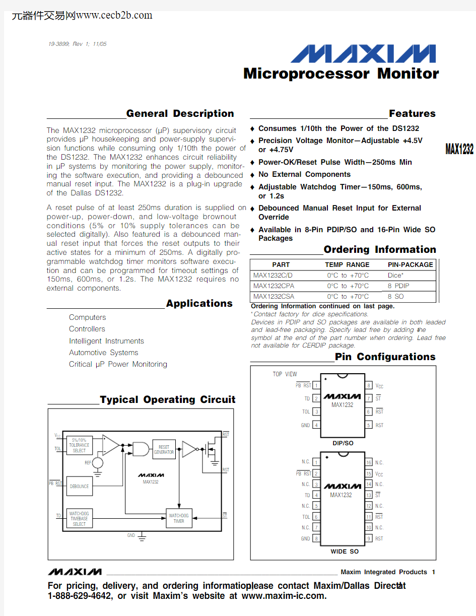
Pin Configurations
Ordering Information
Typical Operating Circuit
19-3899; Rev 1; 11/05
For pricing, delivery, and ordering information,please contact Maxim/Dallas Direct!at 1-888-629-4642, or visit Maxim’s website at https://www.360docs.net/doc/9318666164.html,.
*Contact factory for dice specifications.
Devices in PDIP and SO packages are available in both leaded and lead-free packaging. Specify lead free by adding the +symbol at the end of the part number when ordering. Lead free not available for CERDIP package.
M A X 1232
Microprocessor Monitor 2_______________________________________________________________________________________
ABSOLUTE MAXIMUM RATINGS
Recommended DC Operating Conditions
Stresses beyond those listed under “Absolute Maximum Ratings” may cause permanent damage to the device. These are stress ratings only, and functional operation of the device at these or any other conditions beyond those indicated in the operational sections of the specifications is not implied. Exposure to absolute maximum rating conditions for extended periods may affect device reliability.
Voltage on Any Pin (with respect to GND)……………-1V to +7V Operating Temperature Range
C Suffix………………………………………………0°C to +70°C E Suffix.……………………………………………-40°C to +85°C M Suffix .…………………………………………-55°C to +125°C
Storage Temperature Range……………………-65°C to +160°C Lead Temperature (soldering, 10s)………………………+300°C
Capacitance (Note 4)
DC Electrical Characteristics
(V
= +4.5V to +5.5V, T = T to T )
MAX1232
Microprocessor Monitor
_______________________________________________________________________________________3
Note 1:PBRST is internally pulled up to V CC with an internal impedance of typically 40k ?.Note 2:Measured with outputs open.Note 3:All voltages referenced to GND.Note 4:Guaranteed by desing.
Note 5:PBRST must be held low for a minimum of 20ms to guarantee a reset.Note 6:t R = 5μs.
AC Electrical Characteristics
M A X 1232
Detailed Description
Power Monitor
A voltage detector monitors V CC and holds the reset outputs (RST and RST ) in their active states whenever V CC is below the selected 5% or 10% tolerance (4.62V or 4.37V, typically). To select the 5% level, connect TOL to ground. To select the 10% level, connect TOL to V CC . The reset outputs will remain in their active states until V CC has been continuously in-tolerance for a mini-mum of 250ms (the reset active time) to allow the power supply and μP to stabilize.
The RST output both sinks and sources current, while the RST output, an open-drain MOSFET, sinks current only and must be pulled high.
Pushbutton Reset Input
The MAX1232’s debounced manual reset input (PBRST ) manually forces the reset outputs into their active states. The reset outputs go active after PBRST has been held low for a time t PBD , the pushbutton reset delay time. The reset outputs remain in their active states for a minimum of 250ms after PBRST rises above V IH (Figure 3).
A mechanical pushbutton or an active logic signal can drive the PBRST input. The debounced input ignores input pulses less than 1ms and is guaranteed to recog-nize pulses of 20ms or greater. The PBRST input has an internal pullup to V CC of about 100μA; therefore, an external pullup resistor is not necessary.
Watchdog Timer
The microprocessor drives the ST input with an input/output (I/O) line. The microprocessor must toggle the ST input within a set period (as determined by TD)to verify proper software execution. If a hardware or software failure keeps ST from toggling within the mini-mum timeout period—ST is activated only by falling edges (a high-to-low transition)—the MAX1232 reset outputs are forced to their active states for 250ms (Figure 2). This typically initiates the microprocessor’s power-up routine. If the interruption continues, new reset pulses are generated each timeout period until ST is strobed. The timeout period is determined by the TD input connection. This timeout period is typically 150ms with TD connected to GND, 600ms with TD floating, or 1200ms with TD connected to V CC .
The software routine that strobes ST is critical. The code must be in a section of software that executes fre-quently enough so the time between toggles is less than the watchdog timeout period. One common tech-nique controls the microprocessor I/O line from two sections of the program. The software might set the I/O line high while operating in the foreground mode, and set it low while in the background or interrupt mode. If both modes do not execute correctly, the watchdog timer issues reset pulses.
Microprocessor Monitor 4_______________________________________________________________________________________
Figure 1. Pushbutton Reset Figure 2. Watchdog Timer
MAX1232
Microprocessor Monitor
_______________________________________________________________________________________5
ignores input pulses less than 1ms and is guaranteed to rec-ognize pulses of 20ms or greater.
M A X 1232
Microprocessor Monitor Maxim cannot assume responsibility for use of any circuitry other than circuitry entirely embodied in a Maxim product. No circuit patent licenses are implied. Maxim reserves the right to change the circuitry and specifications without notice at any time.
6_____________________Maxim Integrated Products, 120 San Gabriel Drive, Sunnyvale, CA 94086 408-737-7600?2005 Maxim Integrated Products
is a registered trademark of Maxim Integrated Products, Inc.
Package Information
For the latest package outline information, go to https://www.360docs.net/doc/9318666164.html,/packages .
0.099"(2.51 mm)
0.070"(1.78 mm)
ST
RST
RST
GND
TD
TOL
PB RST
V
CC
Ordering Information (continued)
Chip Topography
*Contact factory for dice specifications.
Devices in PDIP and SO packages are available in both leaded and lead-free packaging. Specify lead free by adding the +symbol at the end of the part number when ordering. Lead free not available for CERDIP package.