Lauron V a versatile six-legged walking robot with advanced maneuverability
LAURON V:A Versatile Six-Legged Walking Robot with Advanced Maneuverability
A.Roennau1,G.Heppner1,M.Nowicki2and R.Dillmann1
Abstract—Adaptive multi-legged walking robots are predes-tined to be applied in rough and hazardous terrain.Their walking and climbing skills allow them to operate at places that are unreachable for most wheeled vehicles.In this paper, we present the design and development of the new six-legged walking robot LAURON V with its improved kinematics and robust mechanical structure.Each leg has four independent joints that enable LAURON to cope with steep inclines,large obstacles and makes it possible to manipulate objects with its front legs.Autonomy,robustness and a large payload capacity together with its impressive terrain adaptability make LAURON V highly suitable for all kinds of?eld applications.
I.I NTRODUCTION
Walking robots,especially hexapods,are designed to walk in dif?cult,rough and often unknown terrain.Stable loco-motion in such an environment,however,is not easy and therefore many researcher around the world continuously develop new concepts to improve a variety of legged robots. The FZI Research Center for Information Technology has a long standing tradition of walking robots[1],[2].In particular the LAURON hexapods[3],[4],[5],[6]reach back over20years.With each iteration this biologically inspired hexapod was made more robust,learned new skills and continued to extend the previous research results.Of course,there are other walking robots that show advanced walking skills like HyQ[7]or LS3[8].Many six-legged walking robots apply the predominant yaw-pitch-pitch kine-matics,which is based on the typical insect-like leg design with three joints:Messor II[9],AMOS-WD06[10],BILL-Stick[11],DLR Crawler[12]and Anton[13].The impressive number of18degrees of freedom(DoF)offers a good ?exibility and walking abilities on mainly?at terrain with obstacles.However,if the terrain becomes more challenging, as it is the case with larger obstacles or steep slopes,this kinematic design reaches its limit as the orientation of the feet cannot be chosen freely.Some of these limitations are addressed by sophisticated motion planning methods and foothold selection approaches[14],[15],[16].But of course, these approaches require detailed environmental information and an exact robot localization.Certainly,there are also many multi-legged walking robots with an advanced leg design (more than three degrees of freedom per leg):CR200[17], Athlete[18],LEMUR[19]and CREX[20].Their additional 1A.Roennau,G.Heppner and R.Dillmann are with the Depart-ment of Interactive Diagnosis and Service Systems at the FZI Re-search Center for Information Technology,D-76131Karlsruhe,Germany roennau,heppner,dillmanng@fzi.de
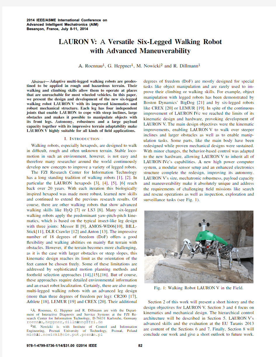
2M.Nowicki is with Institute of Control and Information Engineering,Pozna′n University of Technology,Pozna′n,Poland michal.nowicki@cie.put.poznan.pl degrees of freedom(DoF)are mostly designed for special tasks like object manipulation and are rarely used to im-prove their climbing or walking skills.For example,object manipulation with legged robots has been demonstrated by Boston Dynamics’BigDog[21]and by six-legged robots like CREX[20]or LEMUR[19].In spite of the continuous improvement of LAURON IVc we reached the limits of its kinematic design and hardware,provoking development of LAURON V.The main design objectives were the kinematic improvements,enabling LAURON V to walk over steeper inclines and larger obstacles as well as to enable manip-ulation tasks.Some parts,like the main body have been redesigned while proven mechanical designs were sustained. With minor changes,the behavior-based control was adapted to the new hardware,allowing LAURON V to inherit all of LAURON IVc’s capabilities.A new high power computer system,a modular sensor setup and an enhanced electronics structure complete the redesign,improving its autonomy. LAURON V’s size,mechatronic robustness,payload capacity and maneuverability make it absolutely unique and address the requirements of challenging?eld missions like search and rescue operations as well as inspection,exploration and surveillance tasks(see Fig.
1).
Fig.1:Walking Robot LAURON V in the Field. Section2of this work will present a short history and the design objectives for LAURON V.Section3and4focus on kinematics and mechanical design.The hierarchical control architecture will be described in https://www.360docs.net/doc/a55447696.html,URON V’s advanced skills and the evaluation at the EU Taranis2013 are content of the Sections6and7.Finally,Section8will conclude our work and give a short outlook to future work.
2014 IEEE/ASME International Conference on
Advanced Intelligent Mechatronics (AIM)
Besan?on, France, July 8-11, 2014
978-1-4799-5736-1/14/$31.00 ?2014 IEEE82
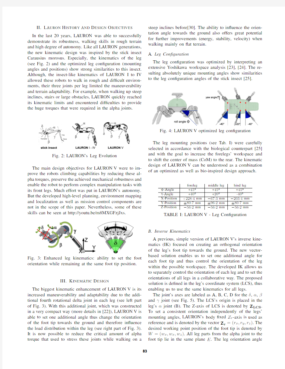
II.L AURON H ISTORY AND D ESIGN O BJECTIVES In the last 20years,LAURON was able to successfully demonstrate its robustness,walking skills in rough terrain and high degree of autonomy.Like all LAURON generations,the new kinematic design was inspired by the stick insect Carausius morosus.Especially,the kinematics of the leg (see Fig.2)and the optimized leg con?guration (mounting angles and positions)show strong similarities to this insect.Although,the insect-like kinematics of LAURON I to IV allowed these robots to walk in rough and dif?cult environ-ments,their three joints per leg limited the maneuverability and terrain adaptability.For example,when walking up steep inclines,stairs or large obstacles,LAURON quickly reached its kinematic limits and encountered dif?culties to provide the huge torques that were required in the alpha
joints.
Fig.2:LAURON’s Leg Evolution
The main design objectives for LAURON V were to im-prove the robots climbing capabilities by reducing these al-pha torques,preserve the achieved mechanical robustness and enable the robot to perform complex manipulation tasks with its front legs.Much effort was put in LAURON’s autonomy.But the developed high-level planning,environment mapping and localization as well as mission control components are not in the scope of this paper.Nevertheless,some of these skills can be seen at
http://youtu.be/m8MXGFzjJxs.
Fig.3:Enhanced leg kinematics:ability to set the foot orientation while remaining at the same foot tip position.
III.K INEMATIC D ESIGN
The biggest kinematic enhancement of LAURON V is its increased maneuverability and adaptability due to the addi-tional fourth rotational delta joint in each leg (see left part of Fig.3).With this additional joint,which was constructed in a very compact way (more details in [22]),LAURON V is able to set one additional angle thus change the orientation of the foot tip towards the ground and therefore in?uence the load distribution within the leg (see right part of Fig.3).It is now possible to reduce the critical amount of alpha torque that used to stress these joints while walking on a
steep inclines before[30].The ability to in?uence the orien-tation angle towards the ground also offers great potential for further improvements (energy,stability,velocity)when walking mainly on ?at terrain.A.Leg Con?guration
The leg con?guration was optimized by interpreting an extensive Yoshikawa workspace analysis [23],[24].The re-sulting absolutely unique mounting angles show similarities to the leg con?guration angles of the stick insect
[25].
Fig.4:LAURON V optimized leg con?guration The leg mounting positions (see Tab.I)were carefully selected in accordance with the biological counterpart [25]and with the goal to increase the forelegs’workspace and to shift the center of mass (CoM)to the rear.The kinematic design of LAURON V can be understood as a combination of an optimized as well as bio-inspired design approach.
foreleg middle leg hind leg Φ-Angle +45?+45?+45?η-Angle +40?
+20?-40?
X-Position +228.4mm ?67.3mm ?203.4mm Y-Position ±80.7mm ±96.2mm ±80.7mm Z-Position
?56.2mm
?56.2mm
?56.2mm
TABLE I:LAURON V -Leg Con?guration
B.Inverse Kinematics
A previous,simple version of LAURON V’s inverse kine-matics (IK)focused on creating an orthogonal orientation of the leg’s foot tip towards the ground.The new vector-based solution enables us to set one additional angle for each foot tip and thus control the orientation of the leg within the possible workspace.The developed IK allows us to separately control the orientation of each leg and to set the orientations of all legs in a collaborative way.The proposed solution is de?ned in the leg’s coordinate system (LCS),thus enabling us to use the same kinematics for all legs.
The joint’s axes are labeled as A,B,C,D for the δ,α,βand γjoint (see Fig.5).The LCS’s origin is placed in the leg’s αjoint (B).The Z-axis of LCS is denoted by Z LCS .To set a consistent orientation independently of the legs’mounting angles,LAURON’s body ?xed Z r -axis is used as reference and is denoted by the vector Z r =(r x ,r y ,r z ).The desired working point position of the foot tip is denoted by W =(w x ,w x ,w z ).All leg parts from the alpha joint to the foot tip lie in the same plane E .The leg orientation angle
83
Fig.5:Points A,B,C,D are placed in the joint axes.
ψis the angle between the vector Z r and plane E (in X r direction).
First,the proposed algorithm determines the parame-ters of the plane E represented by the four parameters:P a ,P b ,P c ,P d .They are used in the plane equation:
P a x +P b y +P c z +P d =0.
(1)
Equation (1)is satis?ed by every point (x,y,z )that lies on the plane.The normal vector of the plane n E is de?ned by (P a ,P b ,P c ).The IK makes use of the desired foot tip position W and desired leg orientation ψto ?nd the corresponding joint angles.The computations begin with solving a system of equations to ?nd the parameters of E ,that satisfy the imposed constraints:
P a 0+P b 0+P c 0+P d =0P a w x +P b w y +P c w z +P d =0
P a r x +P b r y +P c r z =cos (
π
2
?ψ)P 2a +P 2b +P 2c =1
(2a)(2b)
(2c)(2d)
The ?rst constraint is represented by (2a)and stems from the fact,that the origin of the LCS must lie in the plane E and therefore satis?es (1).The equation (1)must also be satis?ed by the desired foot point W ,which is formulated in (2b).Equation (2c)is imposed by the desired ψangle.If the angle between the plane E and the vector Z r is equal to ψ,then the angle between the normal vector of the plane n E and vector Z r is equal to the ψ?π2.Equation (2d)is the normalization constraint of the normal of the plane n E .Only one of the two solutions is valid due to the de?nition of the direction of the positive angle ψ.
With knowledge of the plane E ,the individual joint angles can be computed.The δangle is calculated as the angle between leg plane E and the vector Z LCS .The computation is performed using the normal vector of the plane n E .From Fig.5it might appear that the normal vector of the plane n E should be rotated by ?αabout the vector Z LCS prior to δcalculation,but this operation is omitted as the angle between two arbitrary real-valued vectors remain constant if the rotations are performed about these vectors.The α
angle is computed as the angle between vectors ??→
BC and ??→AB ,whereas βangle is the angle between vectors ??→CD and ??→
BC .The remaining γangle is equal to the angle between
vectors ??→DW and ??→
CD .Concluding,the IK problem can be solved with the following equations:
δ=π
2
?arccos(Z lcs ·n E )α=arccos(??→BC ·??→
AB )
β=arccos(??→CD ·??→
BC )
γ=arccos(??→DW ·??→
CD )
(3a)
(3b)(3c)(3d)The analytical form of the proposed solution is not com-putationally demanding and can be calculated fast.This
new inverse kinematics has been successfully tested on LAURON V and signi?cantly expands LAURON’s climbing skills on slopes.
IV.M ECHANICAL D ESIGN
Within the last nine years LAURON IVc’s mechanical leg design proved to be reliable and robust.This design was adapted and improved for better maintenance [22].In contrast to its ancestors LAURON V’s main body is now made of an inner-skeleton like structure.The basic shape of this structure follows a design concept,that was evaluated in a very early stage of development.In this phase,we also decided to develop an abdomen for the control PC in the rear of the robot.It additionally shifts the CoM to the rear,making it easier to manipulate with its front legs and creates a natural look.A light-weight plastic casing/skin and strong 3D-printed shells on the bottom protect all internal
parts.
Fig.6:Structure Optimization of Inner-Skeleton The inner structure is the result of an iterative wire-frame optimization routine.The thickness of each element was optimized to endure the stress induced during the walk-ing process.Finally,the complex wire-frame structure (see Fig.6)was re?ned to the simpli?ed,inner-skeleton frame made of high-strength aluminum as shown in Fig.
7.
Fig.7:Inner-Skeleton made from High-Strength Aluminum After ?rst experiments and endurance tests some mechan-ical improvements have been carried out.The inner-skeleton
84
has proven to be extremely robust,and was therefore partially redesigned to reduce weight.Besides,the gear belts of the beta joints,which carry the largest amount of the robot’s weight,have been replaced by more reliable steel chains.
A.Technical Speci?cations
The most important technical speci?cations that character-ize LAURON V are summarized in Table II.
LAURON V
Type Legged Walking Robot
No.of Legs6
No.of Joints per Leg4(delta,alpha,beta,gamma)
No.of Head Joints2(pan&tilt)
Total DOF(active)26
Compliance Spring damper in each foot(6passive DOF) Size[footprint]0.9m x0.8m
Height[min-max]0.61m-0.84m(form ground to PTU head) Weight40kg(+2kg for batteries)
Max Payload10kg
Power Supply>2hours with2x22.2V8Ah(LiPo)
Power Consumption Standing:100W,Walking150W
On-board PC Intel Core i74x3.0GHz with8GB RAM
Modular Sensors IR-Camera,Stereo-Camera,RGB-D,
Velodyne HDL-32E,Rotating Hokuyo
TABLE II:LAURON V-Speci?cations
V.C ONTROL D ESIGN
A modular,behavior-based design approach allows us to subdivide this system into understandable hierarchical layers and small individual behaviors.
A.Hardware Architecture
LAURON’s on-board PC with its Intel Core i7CPU offers suf?cient computational power to run
all software,the behavior-based control system and the hardware abstraction layer,on the robot.The low-level PID-Joint-Controllers run on9custom motor controller boards(UCoM-Universal Controller Modules[26])that are connected to the control PC via CAN bus interface.The control center,including a 3D model of the robot and all relevant control interfaces,is executed on an independent external PC.More details on the control hardware of LAURON V can be found in Fig.8. B.HAL-Hardware Abstraction Layer
LAURON’s hardware abstraction layer is used to?lter data,multiplex and convert values(e.g.sensor ticks to gradi-ent angles)and solve the direct and inverse kinematics.For example,the HAL adds the robot speci?c offsets to the IMU raw values and transforms them to the correct robot frame. All motor currents are normalized and scaled with a non-linear function[27]and the ground contact values are?ltered by a combination of mean and median?https://www.360docs.net/doc/a55447696.html,pared to
Fig.8:LAURON V Control Hardware Architecture other components,the calculation of the inverse kinematics (see Section III)is a rather complex part in the HAL.By placing HAL between behavior-based control system and the low-level motor controllers,the control systems remains largely robot independent.By following this design principle it was easy to transfer the control system from LAURON IVc to LAURON V.In fact,we were able to quickly reuse the behavior-based control by adapting the HAL to the characteristics of LAURON V within a few hours.
C.Behavior-Based Control System
In the last years,LAURON has successfully been con-trolled by a behavior-based control systems[28].A general-ized system architecture with the most important behaviors can be seen in Fig.9.The desired velocities(x,y,α)and the walking patterns(tri-,tetra-,pentapod and free gait)are given as external inputs.This input can either come directly from the control center or from higher software components (path planning,mission control,etc.).Foot point generating behaviors calculate the AEP(Anterior Extreme Position), PEP(Posterior Extreme Position),swing height and the resulting step cycle.Gait behaviors motivate the swing or stance behavior of each leg and coordinate the legs to gen-erate the desired patterns.Behavior fusions are responsible for a smooth transitions and intelligent combination of all values.For example:the step size(AEP and PEP)and step frequency are only increased by a small delta each walking step until the desired overall robot velocity has been reached.
Parameters from these behaviors and motivation signals are used in the local leg behavior groups to generate the leg and body movements.Each independent local leg behavior group consists of a swing,stance and re?ex behaviors(collision de-tection and ground contact).The swing and stance behavior are motivated by the walking pattern behaviors.The re?exes are directly motivated by the swing and stance behaviors and then triggered by sensor data(i.e.currents or ground contacts).The posture behaviors generate shifts and offsets to control the body’s inclination,height and position.All 85
these behaviors combine their outputs to a position (X,Y,Z )and orientation angle (ψ)for each leg.The IK within the HAL determines all corresponding joint angles,the UCoMs control the motors and read all internal sensor values.
This modular architecture and its abstract control scheme enable LAURON to walk over unknown terrain without intensive planning or human intervention.It can easily be extended by further behaviors and modi?ed by replacing individual behaviors,which has lead to a continuous growth and re?nement of LAURON’s control
system.
Fig.9:Behavior-based control system of LAURON V
VI.A DVANCED S KILLS
The new leg kinematics and the special mounting increase LAURON’s overall performance,but also enable completely novel skills that extend its capabilities.A.Increased Maneuverability
Steep slopes have been a challenge for LAURON IVc as very high torques are needed in these situations.With the additional joint,LAURON V is able to align its legs parallel to the gravity vector,reducing the stress on the legs signi?cantly (see Fig.10).This joint is actively used by reactive posture behaviors,which then improves LAURON’s performance to keep its body balanced and walk up steep slopes or over large obstacles.Now,LAURON V is able to autonomously walk up slopes with an inclination larger than 25.0degrees and remained stable until 42.8degree
[30].
Fig.10:Increased maneuverability on steep slopes:(left)LAURON IVc is not able to orientate its legs,(right)LAURON V with PSI angle control -leg orientation (IK +posture control)decreases torques and increases stability.B.Dual and Single Leg Manipulation
By shifting the center of mass towards the rear,LAURON can stand on its 4hind legs,leaving the 2front legs free for manipulation tasks.In contrast to LAURON IVc the new leg kinematics can reach targets from various angles and lift objects with both legs.A new fully retractable gripper makes LAURON capable of single leg manipula-tion,where grasped objects can be stored on its back (see Fig.11).Making use of the legs as manipulators saves the weight of an additional robotic arm.A video showing LAURON’s successful grasp with a single leg can be seen at:
http://youtu.be/m8MXGFzjJxs.
Fig.11:LAURON uses its front leg with a light-weight gripper to pick up objects and store them on its back.
VII.F IELD E XPERIMENTS
As part of the robotic exhibition,LAURON V was ?rst presented to the public during the IEEE ICRA 2013in Karlsruhe,Germany.Shortly afterwards,LAURON took part in the EU Taranis Field Exercise in Salzburg,Austria.A.Modular Sensor Setup
The on-board motherboard offers a variety of standard interfaces (USB 3.0/2.0,LAN,RS232,WLAN)which are extended by a CAN interface card.A ?exible mounting system,together with a 24V and 12V supply voltage,make it easy to quickly change the sensors mounted to the pan-tilt head or the back.Due to its great payload capacity (see Table II)large sensors like the Velodyne HDL-32E can be carried with hardly any effects on the https://www.360docs.net/doc/a55447696.html,URON’s modular sensor setup and its superior walking abilities make it a versatile multi-purpose research platform suitable for a great number of hazardous and challenging applications.
86
B.Evaluation at Taranis Field
Exercise
Fig.12:Search and Rescue Tasks at Chemical Accident Site
Golling during the EU Taranis Field Exercise,Austria.
The EU Taranis Field Exercise took place at different
exercise sites all located around the city of Salzburg,Aus-
tria[29].Almost1000international rescue workers from
various organizations trained and demonstrated their skills
during this large scale?eld https://www.360docs.net/doc/a55447696.html,URON V was part of
the SAR Robots team of the Bavarian Red Cross.It supported
a search and rescue operation at the Chemical Accident
Site Golling(see Fig.12).Its infrared camera gave valuable
information to the rescue workers and supported them in
?nding buried casualties after the ceiling of a building had
https://www.360docs.net/doc/a55447696.html,pared to search and rescue dogs,LAURON
can be applied for a longer time and can also provide sensor
data(live videos,pictures,3D maps of environments,etc.).
Nevertheless,LAURON’s climbing and walking skills still
need further improvements to match the capabilities of a
professional search and rescue dog.There were no special,
technical arrangements to support any robots at this exercise.
The primary goal was to create a realistic exercise for the
human rescue workers.Nevertheless,LAURON V performed
quite well in this real world scenario and demonstrated that
its autonomy,robustness and?exibility make walking robots
valuable for search and rescue missions.
VIII.C ONCLUSIONS AND F UTURE W ORKS
In this work we presented the design,development and
evaluation of the?fth LAURON walking robot generation.
Similar to its ancestors,the kinematics and control system
were inspired by the stick insect.The new leg design,to-
gether with the optimized leg con?guration enable LAURON
to cope with dif?cult obstacles and steep inclines.Due to the
increased workspace of the legs and the ability to orientate
its feet freely,LAURON V can be used for complex mobile
manipulation tasks.Real?eld applications have demon-
strated that its robust mechatronics ful?ll the requirements of
demanding search and rescue missions in the wake of natural
disasters.In the future,we will extend LAURON’s walking
range by applying energy ef?cient locomotion strategies and
further increase the system’s autonomy by enhancing its
planning and mission control components as well as its
reactive behaviors[30].
R EFERENCES
[1]J.C.Albiez et al.,“Reactive re?ex-based control for a four-legged
walking machine,”in Robotics and Autonomous Systems,44.3,2003.
[2]T.Kerscher et al.,“Joint control of the six-legged robot AirBug driven
by?uidic muscles,”in Robot Motion and Control(RoMoCo),2002.
[3]K.Berns et al.,“Adaptive,neural control architecture for the walking
machine LAURON,”in Proc.of the IEEE/RSJ/GI Int.Conf.on
Intelligent Robots and Systems(IROS),1994.
[4]S.Cordes et al.,“Sensor components of the six-legged walking
machine LAURON II,”in Proc.of8th International Conference on
Advanced Robotics(ICAR),1997.
[5] B.Gassmann et al.,“Behavior Control of LAURON III for Walking
in Unstructured Terrain,”in CLAWAR2001,Int.Conf.on Climbing
and Walking Robots,2001.
[6] A.Roennau et al.,“Fault diagnosis and system status monitoring for
a six-legged walking robot,”in Proc.of IEEE/ASME Int.Conf.on
Advanced Intelligent Mechatronics(AIM),2011.
[7]T.Boaventura et al.,“Stability and performance of the compliance
controller of the quadruped robot HyQ,”in Proc.IEEE/RSJ Int.Conf.
on Intelligent Robots and Systems(IROS),2013.
[8]LS3-Legged Squad Support Systems,Boston Dynamics:Dedi-
cated to the Science and Art of How Things Move,[online]2013,
https://www.360docs.net/doc/a55447696.html,/robot ls3.html(Accessed:Feb.2014).
[9] D.Belter,K.Walas,“A Compact Walking Robot–Flexible Research
and Development Platform,”in Advances in Intelligent Systems and
Computing,J.Kacprzyk(Ed.),Springer,2014(in print)
[10]P.Manoonpong,F.Woergoetter,“Biologically-Inspired Reactive Walk-
ing Machine AMOS-WD06,”in Proc.of Int.Symposium on Adaptive
Motion of Animals and Machines(AMAM),2008.
[11]W.A.Lewinger et al.,“A hexapod robot modeled on the stick insect,
Carausius morosus,”in Proc.Inter.Conf.on Advanced Robotics
(ICAR),2011.
[12]M.Gorner et al.,“The DLR-Crawler:A testbed for actively compliant
hexapod walking based on the?ngers of DLR-Hand II,”in Proc.
IEEE/RSJ Int.Conf.on Intelligent Robots and Systems(IROS),2008.
[13]M.Konyev et al.,“Walking robot ANTON:Design,simulation,
experiments,”in Proc.of11th Int.Conf.on Climbing and Walking
Robots(CLAWAR),2008.
[14] D.Belter,P.Skrzypczyski,“Rough terrain mapping and classi?cation
for foothold selection in a walking robot,”in Journal of Field Robotics,
vol.28(4),2011.
[15]J.Z.Kolter et al.,“A control architecture for quadruped locomotion
over rough terrain,”in Proc.IEEE Int.Conf.on Robotics and Automa-
tion(ICRA),2008.
[16] A.Roennau et al.,“Six-legged walking in rough terrain based on
foot point planning,”in Proc.Conf.on Climbing and Walking Robots
(CLAWAR),2009.
[17] B.-H.Jun et al.,“Development of seabed walking robot CR200,”in
MTS/IEEE OCEANS,Bergen,2013.
[18] B.H.Wilcox et al.,“ATHLETE:A cargo handling and manipulation
robot for the moon,”in Journal of Field Robotics,vol.24(5),2007.
[19] B.Kennedy et al.,“Limbed Excursion Mechanical Utility Rover:
LEMUR II,”in Proc.Int.Astronautical Congress,2002.
[20]T.M.Roehr et al.,“Recon?gurable Integrated Multirobot Exploration
System(RIMRES):Heterogeneous Modular Recon?gurable Robots
for Space Exploration,”in Journal of Field Robotics,2014.
[21]Mobile Manipulation with BigDog:”Dynamic Robot Manipulation”,
[online]2013,http://youtu.be/2jvLalY6ubc(Accessed:Feb.2014).
[22] A.Roennau et al.,“Design and kinematics of a biologically-inspired
leg for a six-legged walking machine,”in Proc.Conf.on Biomedical
Robotics and Biomechatronics(BioRob),2010.
[23]Tsuneo Yoshikawa,“Manipulability of Robotic Mechanisms,”in The
International Journal of Robotics Research,1985.
[24] A.Roennau et al.,“LAURON V:Optimized Leg Con?guration for
the Design of a Bio-Inspired Walking Robot,”in Proc.Conference on
Climbing and Walking Robots(CLAWAR),2013.
[25]Holk Cruse,“The function of the legs in the free walking stick insect,
Carausius morosus,”in Journal of Comparative Physiology A,1976.
[26]K.Regenstein et al.,“Universal Controller Module(UCoM)-com-
ponent of a modular concept in robotic systems,”in Proc.of IEEE
International Symposium on Industrial Electronics,2007.
[27] A.Roennau et al.,“On-board Energy Consumption Estimation for a
Six-Legged Walking Robot,”in Proc.Conference on Climbing and
Walking Robots(CLAWAR),2011.
[28]T.Kerscher et al.,“Behaviour-based control of a six-legged walking
machine LAURON IVc,”in Proc.of Conference on Climbing and
Walking Robots(CLAWAR),2008.
[29]The Disaster Control Exercise-EU Taranis2013,Salzburg,Austria,
www.taranis2013.eu(Accessed:February2014).
[30] A.Roennau et al.,“Reactive posture behaviors for stable legged
locomotion over steep inclines and large obstacles,”to appear at Proc.
IEEE/RSJ Inter.Conf.on Intelligent Robots and Systems(IROS),2014.
87