Congestion and Power Integrity Aware Placement and Routing for 3D Packaging
Congestion and Power Integrity Aware Placement and Routing for3D Packaging
Jacob Minz,Jinwoo Choi,Madhavan Swaminathan,and Sung Kyu Lim
School of Electrical and Computer Engineering
Georgia Institute of Technology
jrminz,jwchoi,madhavan.swaminathan,limsk@https://www.360docs.net/doc/ac9437160.html,
Abstract—One of the major concerns for a3-D package is to deal with power supply noise.Decoupling Capacitances(decap) allocation is a powerful technique to suppress power supply noise. In this work we integrate noise analysis and decap estimation in the?oorplanning process.We also use the global routers results directly to estimate congestion and tight couple global routing with?oorplanning to get a better area/congestion trade-off.Our experiments prove the quality of our approach.We obtain improvements in both decap amount and congestion with only small increase in area,wirelength and runtime.
I.I NTRODUCTION
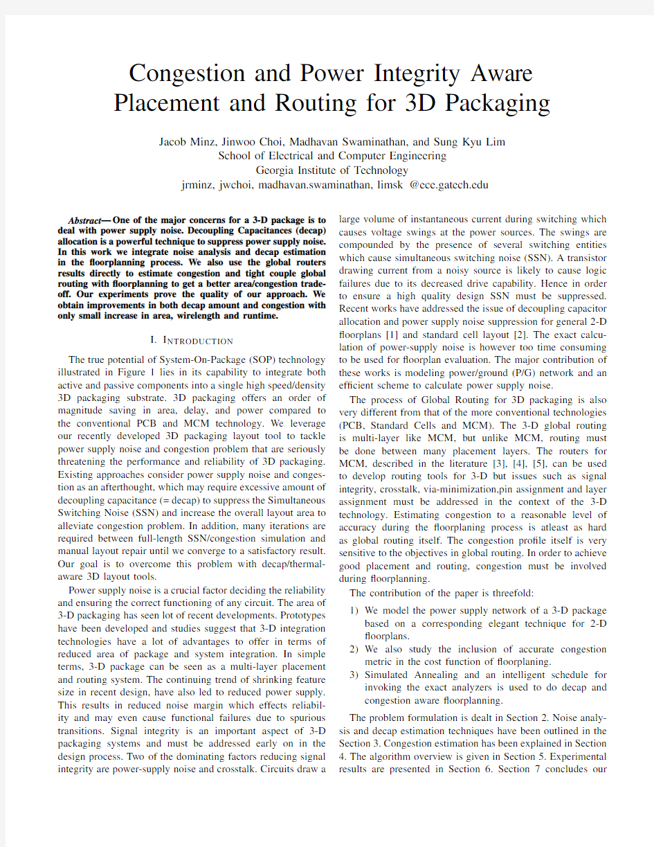
The true potential of System-On-Package(SOP)technology illustrated in Figure1lies in its capability to integrate both active and passive components into a single high speed/density 3D packaging substrate.3D packaging offers an order of magnitude saving in area,delay,and power compared to the conventional PCB and MCM technology.We leverage our recently developed3D packaging layout tool to tackle power supply noise and congestion problem that are seriously threatening the performance and reliability of3D packaging. Existing approaches consider power supply noise and conges-tion as an afterthought,which may require excessive amount of decoupling capacitance(=decap)to suppress the Simultaneous Switching Noise(SSN)and increase the overall layout area to alleviate congestion problem.In addition,many iterations are required between full-length SSN/congestion simulation and manual layout repair until we converge to a satisfactory result. Our goal is to overcome this problem with decap/thermal-aware3D layout tools.
Power supply noise is a crucial factor deciding the reliability and ensuring the correct functioning of any circuit.The area of 3-D packaging has seen lot of recent developments.Prototypes have been developed and studies suggest that3-D integration technologies have a lot of advantages to offer in terms of reduced area of package and system integration.In simple terms,3-D package can be seen as a multi-layer placement and routing system.The continuing trend of shrinking feature size in recent design,have also led to reduced power supply. This results in reduced noise margin which effects reliabil-ity and may even cause functional failures due to spurious transitions.Signal integrity is an important aspect of3-D packaging systems and must be addressed early on in the design process.Two of the dominating factors reducing signal integrity are power-supply noise and crosstalk.Circuits draw a large volume of instantaneous current during switching which causes voltage swings at the power sources.The swings are compounded by the presence of several switching entities which cause simultaneous switching noise(SSN).A transistor drawing current from a noisy source is likely to cause logic failures due to its decreased drive capability.Hence in order to ensure a high quality design SSN must be suppressed. Recent works have addressed the issue of decoupling capacitor allocation and power supply noise suppression for general2-D ?oorplans[1]and standard cell layout[2].The exact calcu-lation of power-supply noise is however too time consuming to be used for?oorplan evaluation.The major contribution of these works is modeling power/ground(P/G)network and an ef?cient scheme to calculate power supply noise.
The process of Global Routing for3D packaging is also very different from that of the more conventional technologies (PCB,Standard Cells and MCM).The3-D global routing is multi-layer like MCM,but unlike MCM,routing must be done between many placement layers.The routers for MCM,described in the literature[3],[4],[5],can be used to develop routing tools for3-D but issues such as signal integrity,crosstalk,via-minimization,pin assignment and layer assignment must be addressed in the context of the3-D technology.Estimating congestion to a reasonable level of accuracy during the?oorplaning process is atleast as hard as global routing itself.The congestion pro?le itself is very sensitive to the objectives in global routing.In order to achieve good placement and routing,congestion must be involved during?oorplanning.
The contribution of the paper is threefold:
1)We model the power supply network of a3-D package
based on a corresponding elegant technique for2-D ?oorplans.
2)We also study the inclusion of accurate congestion
metric in the cost function of?oorplaning.
3)Simulated Annealing and an intelligent schedule for
invoking the exact analyzers is used to do decap and congestion aware?oorplanning.
The problem formulation is dealt in Section2.Noise analy-sis and decap estimation techniques have been outlined in the Section3.Congestion estimation has been explained in Section 4.The algorithm overview is given in Section5.Experimental results are presented in Section6.Section7concludes our
Fig.1.Illustration of embedded passives and3D packaging
paper.
II.P ROBLEM F ORMULATION
Given a set of blocks=,,,,a netlist =,,,,width,height,and maximum switching currents for each block,and the number of placement layers, and constants,,,?nd the location of each block, and placement layer such that
is minimized,where,and are the area,congestion and decap allocation costs for the?oorplan.
III.D ECAP E STIMATION
A.SSN Modeling
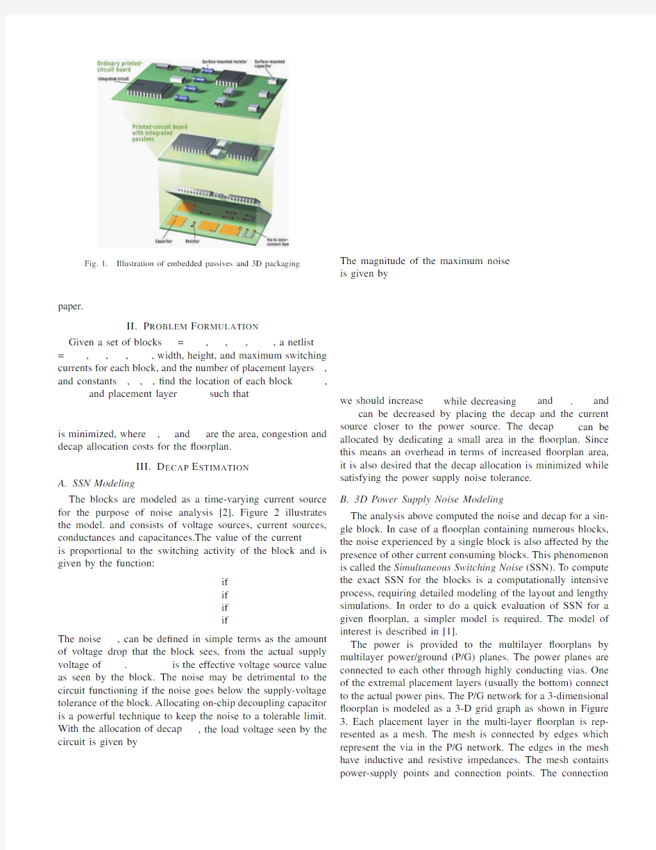
The blocks are modeled as a time-varying current source for the purpose of noise analysis[2].Figure2illustrates the model.and consists of voltage sources,current sources, conductances and capacitances.The value of the current
is proportional to the switching activity of the block and is given by the function:
if
if
if
if
The noise,can be de?ned in simple terms as the amount of voltage drop that the block sees,from the actual supply voltage of.is the effective voltage source value as seen by the block.The noise may be detrimental to the circuit functioning if the noise goes below the supply-voltage tolerance of the block.Allocating on-chip decoupling capacitor is a powerful technique to keep the noise to a tolerable limit. With the allocation of decap,the load voltage seen by the circuit is given by The magnitude of the maximum noise
is given by
we should increase while decreasing and.and can be decreased by placing the decap and the current source closer to the power source.The decap can be allocated by dedicating a small area in the?oorplan.Since this means an overhead in terms of increased?oorplan area, it is also desired that the decap allocation is minimized while satisfying the power supply noise tolerance.
B.3D Power Supply Noise Modeling
The analysis above computed the noise and decap for a sin-gle block.In case of a?oorplan containing numerous blocks, the noise experienced by a single block is also affected by the presence of other current consuming blocks.This phenomenon is called the Simultaneous Switching Noise(SSN).To compute the exact SSN for the blocks is a computationally intensive process,requiring detailed modeling of the layout and lengthy simulations.In order to do a quick evaluation of SSN for a given?oorplan,a simpler model is required.The model of interest is described in[1].
The power is provided to the multilayer?oorplans by multilayer power/ground(P/G)planes.The power planes are connected to each other through highly conducting vias.One of the extremal placement layers(usually the bottom)connect to the actual power pins.The P/G network for a3-dimensional ?oorplan is modeled as a3-D grid graph as shown in Figure 3.Each placement layer in the multi-layer?oorplan is rep-resented as a mesh.The mesh is connected by edges which represent the via in the P/G network.The edges in the mesh have inductive and resistive impedances.The mesh contains power-supply points and connection points.The connection
Fig.3.3D power supply modeling
points consume currents.The current is drawn from all the sources by the consumers and the current drawn along a path is inversely proportional to the impedance of the path in the power supply mesh.If for a particular block,,, be the currents drawn from power sources in the grid then
where is the switching current demand of the block.Then,
where is the impedances of path.If then
where is the current in the path,which is the sum of all currents through this path to various consumer.The weigths of and itsrate of change are the resistive and inductive components of the path.
Let denote the maximum charge drawn from the power supply by block.If,where is the noise tolerance,the decap allocated to block
is given by
Then,is the local congestion in routing in-terval.The congestion of the3-D?oorplan with placement layers is given by
(2)
The value of the congestion determines the number of layers required for routing and is a very important factor during the manufacturing process.A more uniform usage of the grid graph results in lesser congestion.We use results of a fast global router to estimate the exact value of congestion.In the following paragraph we outline the steps of the router.
The global routing is done in many steps[6],[7],[8]as illustrated in Figure5,the essential ones of which are:
1)Net Segmentation:Nets traversing multiple routing in-
tervals are segmented into subnets which are part of the net con?ned to the single interval.
2)Pin Generation:Pins are generated for nets which also
de?nes the locations where the net enters or exits the interval.
3)Net Distribution:Routing Interval is selected for the nets
which have a choice of the routing regions.For example, nets having all its pin the same?oorplan layer can either be routed above or below this layer,if this layer is not the bottommost or topmost of the package.
4)Detailed Pin Distribution:The pins are assigned a legal
location in the routing interval.Special care is taken to distribute the pins uniformly in the routing interval. 5)Topology Generation:A topology for each subnet is
generated in the local grid graph[5].
B.Fast3D Congestion Estimation Algorithm
Since congestion is a part of the cost function used in the?oorplanner,its value needs to be determined after each move.However calling the full-length global router at each move to estimate congestion is not feasible.In order to tackle this problem,the optimization routine runs complete global routing on the candidate con?guration only at certain points according to the scheduling policy.At all other moves the value of congestion must be estimated.We have a very simple method of estimating congestion based on the previous values of actual congestions.Let us assume a very simple policy for calling the global router for accurate congestion analysis,i.e after every?xed number of moves(say).Let the values of area,wirelength,decap and congestion at the call be and at is.If at move
,the parameters of the con?guration is,can be estimated as
Fig.5.3D global routing
current con?guration the area,wirelength and congestion is calculated.If the schedule allows for the current move,the global router is called and the exact congestion is calculated, or else an approximate value of the congestion is estimated is based on previous accurate values of congestion and other metrics as has been outlined in the previous section.The new cost is the weighted sum of all the metrics.If the new cost is lower than the old one,the solution is accepted and the old cost is assigned the new cost.If the new cost is more than the old cost,the solution is accepted with a probability given by an exponential function of the difference of the old and the new cost.Temperature levels are de?ned before hand and at each level certain numbers of moves are made.The temperature levels are decreased by a multiplicative factor.The algorithm stops when the stopping or the freezing temperature is reached.
VI.E XPERIMENTAL R ESULTS
We implemented the proposed algorithms and analysis tools using C++/STL.Our program was evaluated using the GSRC benchmarks.The current demands for the blocks were randomly generated.We designed several experiments to test the ef?ciency of our algorithms.Twenty temperature levels are de?ned and hundred moves are made in each temperature level.We chose our baseline as the layout optimized for wirelength.We de?ne area utilization as the ratio of the area of the sum of the block areas divided by the number of layers to the area of the multi-layer?oorplan.Therefore higher utilization means better solution quality in terms of area. A.Decap/Congestion Optimization Results
We compare our congestion driven and congestion driven ?oorplanning in terms of the four quality metrics,area uti-lization,wirelength,decap amount and congestion in Table I. The baseline is compared with the area,wirelength,decap and congestion driven?oorplanning using frequency of analyzer calls per50moves,in Table II.The impact of the frequency of global router calls is tabulated in Table III,where the solution is measured in terms of decap and congestion.For the calculation of the cost function,the area and wirelength are normalized using a?xed constant.The weights used for the area,wirelength,decap and congestion are1,1,2and1for the multi-objective?oorplanning.For the case of congestion driven optimization we let the weight of congestion in the cost function to vary between1and4.
The results obtained are highly sensitive to the weights of the metrics in the cost factor.In the tables we report the solution,keeping weights of the solution quality metrics constant across the benchmarks.However we noticed that the solution of all circuits can be improved by?ne tuning the parameters.We do notice some predictable trends in the tables which can be summarized as follows.
The decap driven?oorplaning gives reduced decap(av-erage of20%and maximum of25%)for all circuits with only a small percentage decrease in area utilization(19%), since the decap is calculated at each move.
The congestion optimization is highly sensitive to pa-rameters,since we are also using approximate values to accept solutions.There is3%improvement in conges-tion.The maximum improvement of congestion for the benchmarks is15%.
We were able to achieve improvements in both congestion and decap over the baseline with only a slight increase in area(23%on the average)and wirelength(15%on the
TABLE IV
D ECAP-CONGESTION CORRELATION
decap congestion
range ave
n50[0,0.41]0.11 n50b[0,0.81]0.13 n50c[0,0.44]0.10 n100[0,0.72]0.11 n100b[0,0.50]0.12 n100c[0,1.00]0.11 n200[0,1.12]0.10 n200c[0,1.30]0.14 n300[0,1.00]0.11
TABLE I
AREA/WIRE-DRIVEN VS DECAP-DRIVEN VS CONGESTION-DRIVEN
area/wire-driven congestion-driven name size lyr util wire decap cong
n505040.575850319.925
0.734571127.1270.326122251.4523 n50c5040.605163816.424
0.788446990.6400.58105136106.6044 n100b10040.608827778.333
0.7482728100.6410.41117786116.936 n20020040.64211171209.667
0.81181526233.2830.43249897257.682 n200c20040.69195118214.467
0.84286218393.81000.61331029402.994
1.00 1.00 1.00 1.000.62 1.26 1.250.97
TIME40
TABLE II
AREA/WIRE-DRIVEN VS AREA/WIRE/DECAP/CONGESTION-DRIVEN
area/wire-driven
util wire decap cong
n500.645375135.024
n50b0.594818534.023
n50c0.545822426.928
n1000.6310145883.838
n100b0.608115186.231
n100c0.738931691.446
n2000.62207946224.179
n200b0.65219148228.286
n200c0.66200902230.669
n3000.62334278398.595
1.00 1.00 1.00 1.00
32
TABLE III
RUNTIME VS QUALITY TRADEOFF.IMPACT OF THE FREQUENCY OF FULL-LENGTH ANALYSIS ON DECAP AND CONGESTION
decap cong decap cong
n5035.02430.726
n50b34.02331.026
n50c26.92828.726
n10083.83885.443
n100b86.23184.344
n100c91.44684.350
n200224.179229.383
n200b228.286226.881
n200c230.669231.573
n300398.595400.698
1.00 1.000.96 1.06
7560
VII.C ONCLUSION
We have extended power-supply network modeling tech-nique for3-D?oorplans.We also tried to address the issue of congestion during the?oorplanning process.We have outlined a technique to use runtime intensive analyzers during the optimization process and making intelligent approximation of the metrics based on those analysis.Our results show that good results can be obtained and runtime reduced by carefully choosing the weights in the cost function.We also validated the results for decap optimization using accurate analytical tools.
R EFERENCES
[1]S.Zhao,C.-K.Koh,and K.Roy,“Decoupling capacitance allocation
and its application to power supply noise aware?oorplanning,”IEEE Trans.on Computer-Aided Design,pp.81–92,2002.
[2]H.Su,S.Sapatnekar,and S.R.Nassif,“An algorithm for optimal
decoupling capacitor sizing and placement for standard cell layouts,”
in Proc.Int.Symp.on Physical Design,2002,pp.68–73.
[3]J.Cong,“Pin assignment with global routing for general cell design,”
IEEE Trans.on Computer-Aided Design,pp.1401–1412,1991. [4]J.Cong,A.B.Kahng,and K.-S.Leung,“Ef?cient algorithms for the
minimum shortest path steiner arborescence problem with applications to VLSI physical design,”IEEE Trans.on Computer-Aided Design,pp.
24–39,1999.
[5]K.Khoo and J.Cong,“An ef?cient multilayer mcm router based on four-
via routing,”IEEE Trans.on Computer-Aided Design,pp.1277–1290, 1995.
[6]J.Minz and S.K.Lim,“Layer assignment for system on packages,”in
https://www.360docs.net/doc/ac9437160.html, and South Paci?c Design Automation Conf.,2004.
Fig.7.Power supply noise simulation with and without decap insertion.
TABLE V
P OWER SUPPLY NOISE SIMULATION RESULTS.W E REPORT SSN NOISE
FOR EACH BLOCK PLACED IN THE TOP PLACEMENT LAYER.(A)
N ON-OPTIMIZED CASE WITHOUT ANY DECOUPLING CAPACITOR.F ROM
T ABLE I WE NEED26.7DECAP UNITS TO SUPPRESS SSN NOISE.(B)
O PTIMIZED CASE WITHOUT ANY DECOUPLING CAPACITOR.F ROM T ABLE
I WE NEED19.9DECAP UNITS.(C)O PTIMIZED CASE WITH DECOUPLING
CAPACITORS INSERTED.
no decap decap decap
blk
blk1
1.31 1.150.17
blk3
1.58 1.420.22
blk5
1.54 1.270.31
blk7
1.33 1.210.36
blk9
1.34 1.380.32
blk11
1.41 1.350.33
blk13
1.05 1.150.22
ENAS云存储(网盘+文档云)管理系统解决方案
易存云存储系统平台建设 项目方案 北京易存科技 2016-1-25 目录 一、方案概述....................................... (03) 二、方案要求与建设目标.................................0 4 2.1 客户需求分析..................................04 2.2 系统主要功能方案..............................05 三、系统安全方案.................................... (19) 3.1 系统部署与拓扑图...............................19 3.2 文件存储加密...................................21 3.3 SSL协议........................................22 3.4 二次保护机制............................. (23)
3.5 备份与恢复.....................................23 四、系统集成与二次开发.................................24 4.1 用户集成.......................................24 4.2 文件集成.................................... (2) 7 4.3 二次开发.................................... (2) 9 五、典型成功案例.......................................29 六、售后服务体系.................................... (30) 6.1公司概况.......................................30 6.2 服务内容与响应时间............................. 31 一、方案概述 随着互联网时代的到来,企业信息化让电子文档成为企业智慧资产的主要载体。信息流通的速度、强度和便捷度的加强,一方面让我们享受到了前所未有的方便和迅捷,但另一方面也承受着信息爆炸所带来的压力。 传统的文件管理方式已经无法满足企业在业务的快速发展中对文件的安全而高效流转的迫切需求。尤其是大文件的传输与分享,集团公司与分公司,部门与部门之间,乃至与供应商或客户之间频繁的业务往来,显得尤其重要。 文件权限失控严重,版本混乱,传递效率,查找太慢,文件日志无法追溯,历史纸质文件管理与当前业务系统有效整合对接等一系列的问题日渐变的突出和迫切。 该文档描述了北京易存科技为企业搭建文档管理系统平台的相关方案。从海量文件的存储与访问,到文件的使用,传递,在线查看,以及文件的流转再到归档
云课堂系统解决方案
云课堂 技术解决方案
目录 第1章概述 (2) 第2章现状分析及问题 (3) 2.1方案背景 (3) 2.2教育信息化建设的发展 (3) 2.2云课堂的推出 (4) 第3章云课堂技术解决方案 (5) 3.1云终端方案概述 (5) 3.2云课堂解决方案 (5) 3.2.1 云课堂拓扑图 (5) 3.2.2 云课堂教学环境 (6) 3.2.3 云课堂主要功能 (7) 3.2.4 优课数字化教学应用系统功能 (8) 第4章方案优势 (9) 4.1私密性 (9) 4.2工作连续性 (9) 4.3方便移动性 (9) 4.4场景一致性 (9) 4.5长期积累性 (9) 4.6安全稳定性 (10) 4.7易维护性 (10) 4.8高效性 (10) 第5章实际案例 (11)
第1章概述 随着现代信息技术的飞速发展,越来越多的用户更加注重自身信息架构的简便易用性、安全性、可管理性和总体拥有成本。近几年信息化的高速发展,迫使越来越多的教育机构需要采用先进的信息化手段,解决各机构当前面临的数据安全隔离、信息共享、资源整合等实际问题,实现通过改进机器的利用率降低成本,减少管理时间和降低基础设施成本,提高工作效率。 无论是作为云计算的核心技术,还是作为绿色 IT、绿色数据中心的核心技术,虚拟化已经成为 IT 发展的重要方向,也可以说我们正面临着一场 IT 虚拟化、云计算的革命。这场 IT 虚拟化、云计算的革命正在开始席卷全球。 虚拟化技术在解决信息安全、资源利用率提升、简化 IT 管理、节能减排等方面有着得天独厚的优势,通过虚拟化技术,把数据中心的计算资源和存储资源发布给终端用户共享使用,大幅度提高服务器资源利用率,同时通过严格的访问控制,确保数据中心中所存储的安全性。
数据结构实验指导书(2016.03.11)
《数据结构》实验指导书 郑州轻工业学院 2016.02.20
目录 前言 (3) 实验01 顺序表的基本操作 (7) 实验02 单链表的基本操作 (19) 实验03 栈的基本操作 (32) 实验04 队列的基本操作 (35) 实验05 二叉树的基本操作 (38) 实验06 哈夫曼编码 (40) 实验07 图的两种存储和遍历 (42) 实验08 最小生成树、拓扑排序和最短路径 (46) 实验09 二叉排序树的基本操作 (48) 实验10 哈希表的生成 (50) 实验11 常用的内部排序算法 (52) 附:实验报告模板 .......... 错误!未定义书签。
前言 《数据结构》是计算机相关专业的一门核心基础课程,是编译原理、操作系统、数据库系统及其它系统程序和大型应用程序开发的重要基础,也是很多高校考研专业课之一。它主要介绍线性结构、树型结构、图状结构三种逻辑结构的特点和在计算机内的存储方法,并在此基础上介绍一些典型算法及其时、空效率分析。这门课程的主要任务是研究数据的逻辑关系以及这种逻辑关系在计算机中的表示、存储和运算,培养学生能够设计有效表达和简化算法的数据结构,从而提高其程序设计能力。通过学习,要求学生能够掌握各种数据结构的特点、存储表示和典型算法的设计思想及程序实现,能够根据实际问题选取合适的数据表达和存储方案,设计出简洁、高效、实用的算法,为后续课程的学习及软件开发打下良好的基础。另外本课程的学习过程也是进行复杂程序设计的训练过程,通过算法设计和上机实践的训练,能够培养学生的数据抽象能力和程序设计能力。学习这门课程,习题和实验是两个关键环节。学生理解算法,上机实验是最佳的途径之一。因此,实验环节的好坏是学生能否学好《数据结构》的关键。为了更好地配合学生实验,特编写实验指导书。 一、实验目的 本课程实验主要是为了原理和应用的结合,通过实验一方面使学生更好的理解数据结构的概念
交互式多模型算法仿真与分析
硕037班 刘文3110038020 2011/4/20交互式多模型仿真与分析IMM算法与GBP算法的比较,算法实现和运动目标跟踪仿真,IMM算法的特性分析 多源信息融合实验报告
交互式多模型仿真与分析 一、 算法综述 由于混合系统的结构是未知的或者随机突变的,在估计系统状态参数的同时还需要对系统的运动模式进行辨识,所以不可能通过建立起一个固定的模型对系统状态进行效果较好的估计。针对这一问题,多模型的估计方法提出通过一个模型集{}(),1,2,,j M m j r == 中不同模型的切换来匹配不同目标的运动或者同一目标不同阶段的运动,达到运动模式的实时辨识的效果。 目前主要的多模型方法包括一阶广义贝叶斯方法(BGP1),二阶广义贝叶斯方法(GPB2)以及交互式多模型方法等(IMM )。这些多模型方法的共同点是基于马尔科夫链对各自的模型集进行切换或者融合,他们的主要设计流程如下图: M={m1,m2,...mk} K 时刻输入 值的形式 图一 多模型设计方法 其中,滤波器的重初始化方式是区分不同多模型算法的主要标准。由于多模型方法都是基于一个马尔科夫链来切换与模型的,对于元素为r 的模型集{}(),1,2,,j M m j r == ,从0时刻到k 时刻,其可能的模型切换轨迹为 120,12{,,}k i i i k trace k M m m m = ,其中k i k m 表示K-1到K 时刻,模型切换到第k i 个, k i 可取1,2,,r ,即0,k trace M 总共有k r 种可能。再令1 2 1 ,,,,k k i i i i μ+ 为K+1时刻经由轨迹0,k trace M 输入到第1k i +个模型滤波器的加权系数,则输入可以表示为 0,11 2 1 12|,,,,|,,,???k k trace k k k i M k k i i i i k k i i i x x μ++=?∑ 可见轨迹0,k trace M 的复杂度直接影响到算法计算量和存储量。虽然全轨迹的
五种大数据压缩算法
?哈弗曼编码 A method for the construction of minimum-re-dundancy codes, 耿国华1数据结构1北京:高等教育出版社,2005:182—190 严蔚敏,吴伟民.数据结构(C语言版)[M].北京:清华大学出版社,1997. 冯桂,林其伟,陈东华.信息论与编码技术[M].北京:清华大学出版社,2007. 刘大有,唐海鹰,孙舒杨,等.数据结构[M].北京:高等教育出版社,2001 ?压缩实现 速度要求 为了让它(huffman.cpp)快速运行,同时不使用任何动态库,比如STL或者MFC。它压缩1M数据少于100ms(P3处理器,主频1G)。 压缩过程 压缩代码非常简单,首先用ASCII值初始化511个哈夫曼节点: CHuffmanNode nodes[511]; for(int nCount = 0; nCount < 256; nCount++) nodes[nCount].byAscii = nCount; 其次,计算在输入缓冲区数据中,每个ASCII码出现的频率: for(nCount = 0; nCount < nSrcLen; nCount++) nodes[pSrc[nCount]].nFrequency++; 然后,根据频率进行排序: qsort(nodes, 256, sizeof(CHuffmanNode), frequencyCompare); 哈夫曼树,获取每个ASCII码对应的位序列: int nNodeCount = GetHuffmanTree(nodes); 构造哈夫曼树 构造哈夫曼树非常简单,将所有的节点放到一个队列中,用一个节点替换两个频率最低的节点,新节点的频率就是这两个节点的频率之和。这样,新节点就是两个被替换节点的父
数据结构课后习题
第一章 3.(1)A(2)C(3)D 5.计算下列程序中x=x+1的语句频度 for(i=1;i<=n;i++) for(j=1;j<=i;j++) for(k=1;k<=j;k++) x=x+1; 【解答】x=x+1的语句频度为: T(n)=1+(1+2)+(1+2+3)+……+(1+2+……+n)=n(n+1)(n+2)/6 6.编写算法,求一元多项式p n(x)=a0+a1x+a2x2+…….+a n x n的值p n(x0),并确定算法中每一语句的执行次数和整个算法的时间复杂度,要求时间复杂度尽可能小,规定算法中不能使用求幂函数。注意:本题中的输入为a i(i=0,1,…n)、x和n,输出为P n(x0)。算法的输入和输出采用下列方法 (1)通过参数表中的参数显式传递 (2)通过全局变量隐式传递。讨论两种方法的优缺点,并在算法中以你认为较好的一种实现输入输出。 【解答】 (1)通过参数表中的参数显式传递 优点:当没有调用函数时,不占用内存,调用结束后形参被释放,实参维持,函数通用性强,移置性强。 缺点:形参须与实参对应,且返回值数量有限。 (2)通过全局变量隐式传递 优点:减少实参与形参的个数,从而减少内存空间以及传递数据时的时间消耗 缺点:函数通用性降低,移植性差 算法如下:通过全局变量隐式传递参数 PolyValue() { int i,n; float x,a[],p; printf(“\nn=”); scanf(“%f”,&n); printf(“\nx=”); scanf(“%f”,&x); for(i=0;i 云安全管理平台解决方案 北信源云安全管理平台解决方案北京北信源软件股份有限公司 2010 云安全管理平台解决方案/webmoney 2.1问题和需求分析 2.2传统SOC 面临的问题................................................................... ...................................... 4.1资产分布式管理 104.1.1 资产流程化管理 104.1.2 资产域分布 114.2 事件行为关联分析 124.2.1 事件采集与处理 124.2.2 事件过滤与归并 134.2.3 事件行为关联分析 134.3 资产脆弱性分析 144.4 风险综合监控 154.4.1 风险管理 164.4.2 风险监控 174.5 预警管理与发布 174.5.1 预警管理 174.5.2 预警发布 194.6 实时响应与反控204.7 知识库管理 214.7.1 知识共享和转化 214.7.2 响应速度和质量 214.7.3 信息挖掘与分析 224.8 综合报表管理 245.1 终端安全管理与传统SOC 的有机结合 245.2 基于云计算技术的分层化处理 255.3 海量数据的标准化采集和处理 265.4 深入事件关联分析 275.5 面向用户服务的透明化 31云 安全管理平台解决方案 /webmoney 前言为了不断应对新的安全挑战,越来越多的行业单位和企业先后部署了防火墙、UTM、入侵检测和防护系统、漏洞扫描系统、防病毒系统、终端管理系统等等,构建起了一道道安全防线。然而,这些安全防线都仅仅抵御来自某个方面的安全威胁,形成了一个个“安全防御孤岛”,无法产生协同效应。更为严重地,这些复杂的资源及其安全防御设施在运行过程中不断产生大量的安全日志和事件,形成了大量“信息孤岛”,有限的安全管理人员面对这些数量巨大、彼此割裂的安全信息,操作着各种产品自身的控制台界面和告警窗口,显得束手无策,工作效率极低,难以发现真正的安全隐患。另一方面,企业和组织日益迫切的信息系统审计和内控要求、等级保护要求,以及不断增强的业务持续性需求,也对客户提出了严峻的挑战。对于一个完善的网络安全体系而言,需要有一个统一的网络安全管理平台来支撑,将整个网络中的各种设备、用户、资源进行合理有效的整合,纳入一个统一的监管体系,来进行统一的监控、调度、协调,以达到资源合理利用、网络安全可靠、业务稳定运行的目的。云安全管理平台解决方案 /webmoney 安全现状2.1 问题和需求分析在历经了网络基础建设、数据大集中、网络安全基础设施建设等阶段后,浙江高法逐步建立起了大量不同的安全子系统,如防病毒系统、防火墙系统、入侵检测系统等,国家主管部门和各行业也出台了一系列的安全标准和相关管理制度。但随着安全系统越来越庞大,安全防范技术越来越复杂,相关标准和制度越来越细化,相应的问题也随之出现: 1、安全产品部署越来越多,相对独立的部署方式使各个设备独立配置、管理,各产品的运行状态如何?安全策略是否得到了准确落实?安全管理员难以准确掌握,无法形成全局的安全策略统一部署和监控。 2、分散在各个安全子系统中的安全相关数据量越来越大,一方面海量数据的集中储存和分析处理成为问题;另一方面,大量的重复信息、错误信息充斥其中,海量的无效数据淹没了真正有价值的安全信息;同时,从大量的、孤立的单条事件中无法准确地发现全局性、整体性的安全威胁行为。 3、传统安全产品仅仅面向安全人员提供信息,但管理者、安全管理员、系统管理 LZ77压缩算法实验报告 一、实验内容 使用C++编程实现LZ77压缩算法的实现。 二、实验目的 用LZ77实现文件的压缩。 三、实验环境 1、软件环境:Visual C++ 6.0 2、编程语言:C++ 四、实验原理 LZ77 算法在某种意义上又可以称为“滑动窗口压缩”,这是由于该算法将一个虚拟的,可以跟随压缩进程滑动的窗口作为术语字典,要压缩的字符串如果在该窗口中出现,则输出其出现位置和长度。使用固定大小窗口进行术语匹配,而不是在所有已经编码的信息中匹配,是因为匹配算法的时间消耗往往很多,必须限制字典的大小才能保证算法的效率;随着压缩的进程滑动字典窗口,使其中总包含最近编码过的信息,是因为对大多数信息而言,要编码的字符串往往在最近的上下文中更容易找到匹配串。 五、LZ77算法的基本流程 1、从当前压缩位置开始,考察未编码的数据,并试图在滑动窗口中找出最长的匹 配字符串,如果找到,则进行步骤2,否则进行步骤3。 2、输出三元符号组( off, len, c )。其中off 为窗口中匹 配字符串相对窗口边 界的偏移,len 为可匹配的长度,c 为下一个字符。然后将窗口向后滑动len + 1 个字符,继续步骤1。 3、输出三元符号组( 0, 0, c )。其中c 为下一个字符。然后将窗口向后滑动 len + 1 个字符,继续步骤1。 六、源程序 /********************************************************************* * * Project description: * Lz77 compression/decompression algorithm. * *********************************************************************/ #include 根式函数值域 HUA system office room 【HUA16H-TTMS2A-HUAS8Q8-HUAH1688】 探究含有根式的函数值域问题 含根式的函数的值域或者最值问题在高中数学的学习过程中时常遇到,因其解法灵活,又缺乏统一的规律,给我们造成了很大的困难,导致有些学生遇到根式就害怕。为此,本文系统总结此类函数值域的求解方法,供学生参考学习。 1.平方法 例1:求31++-=x x y 的值域 解:由题意知函数定义域为[]1,3-,两边同时平方得:322422+--+=x x y =4+()4212+- +x 利用图像可得[]8,42∈y ,又知?y 0[]22,2∈∴y 所以函数值域为[]22,2 析:平方法求值域适用于平方之后可以消去根式外面未知量的题型。把解析式转化为()x b a y ?+=2 的形式,先求y 2 的范围,再得出y 的范围即值域。 2.换元法 例2: 求值域1)12--=x x y 2)x x y 2 4-+= 解:(1)首先定义域为[)+∞,1,令()01≥-=t x t ,将原函数转化为 [)+∞∈,0t ,?? ????+∞∈∴,815y 析:当函数解析式由未知量的整数幂与根式构成,并且根式内外的未知量的次幂保持一致。可以考虑用代数换元的方法把原函数转化成二次函数,再进行值域求解。 (2)首先,函数定义域为[]2,2-∈x ,不妨设αsin 2=x ,令?? ????-∈2,2ππα 则原函数转化为:??? ? ?+=+=4sin 22cos 2sin 2παααy ?? ????-∈2,2ππα,∴??????-∈+43,44πππα 析:形如题目中的解析式,考虑用三角换元的方法,在定义域的前提下,巧妙地规定角的取值范围,避免绝对值的出现。 不管是代数换元还是三角换元,它的目的都是为了去根式,故需要根据题目灵活选择新元,并注意新元的范围。 3.数形结合法 例3:1)求()()8222+-+= x x y 的值域。 2)求1362222+-++-= x x y x x 的最小值。 解:(1)()()8222+-+=x x y 82++-=x x 其解析式的几何意义为数轴上的一动点x ,到两定点2与-8的距离之和,结合数轴不难得到[]+∞∈,10y (2)解析式可转化为()()41312 2+++=--x x y , 定义域为R ,进行适当的变形 ()()=+++--413122x x ()()()()2031012 222----+++x x , 由它的形式联想两点间的距离公式,分别表示点到点的距离与点的距离之和。 点()0,x P 到()1,1A 和()2,3B 的距离之和。即PB PA y +=,结合图形可知 13min =+'=PB A P y ,其中()1,1-'A 析:根据解析式特点,值域问题转化成距离问题,结合图形得出最值,进而求出了值域。 例4:1) 求x x y x 2312 +--+=的值域 实验名称:LZSS压缩算法实验报告 一、实验内容 使用Visual 6..0 C++编程实现LZ77压缩算法。 二、实验目的 用LZSS实现文件的压缩。 三、实验原理 LZSS压缩算法是词典编码无损压缩技术的一种。LZSS压缩算法的字典模型使用了自适应的方式,也就是说,将已经编码过的信息作为字典, 四、实验环境 1、软件环境:Visual C++ 6.0 2、编程语言:C++ 五、实验代码 #include -- need byte-swap function for big endian CPU */ #define READ_LE32(X) *(uint32_t *)(X) #define WRITE_LE32(X,Y) *(uint32_t *)(X) = (Y) /* this assumes sizeof(long)==4 */ typedef unsigned long uint32_t; /* text (input) size counter, code (output) size counter, and counter for reporting progress every 1K bytes */ static unsigned long g_text_size, g_code_size, g_print_count; /* ring buffer of size N, with extra F-1 bytes to facilitate string comparison */ static unsigned char g_ring_buffer[N + F - 1]; /* position and length of longest match; set by insert_node() */ static unsigned g_match_pos, g_match_len; /* left & right children & parent -- these constitute binary search tree */ static unsigned g_left_child[N + 1], g_right_child[N + 257], g_parent[N + 1]; /* input & output files */ static FILE *g_infile, *g_outfile; /***************************************************************************** initialize trees *****************************************************************************/ static void init_tree(void) { unsigned i; /* For i = 0 to N - 1, g_right_child[i] and g_left_child[i] will be the right and left children of node i. These nodes need not be initialized. Also, g_parent[i] is the parent of node i. These are initialized to NIL (= N), which stands for 'not used.' For i = 0 to 255, g_right_child[N + i + 1] is the root of the tree for strings that begin with character i. These are initialized to NIL. Note there are 256 trees. */ for(i = N + 1; i <= N + 256; i++) g_right_child[i] = NIL; for(i = 0; i < N; i++) g_parent[i] = NIL; } /***************************************************************************** Inserts string of length F, g_ring_buffer[r..r+F-1], into one of the trees (g_ring_buffer[r]'th tree) and returns the longest-match position and length via the global variables g_match_pos and g_match_len. If g_match_len = F, then removes the old node in favor of the new one, because the old one will be deleted sooner. 学生: 科目: 数 学 教师: 刘美玲 一、二次函数和特殊多边形形状 二、二次函数和特殊多边形面积 三、函数动点引起的最值问题 四、常考点汇总 1、两点间的距离公式:()()22B A B A x x y y AB -+-= 2、中点坐标:线段AB 的中点C 的坐标为:??? ??++22 B A B A y y x x , 直线11b x k y +=(01≠k )与22b x k y +=(02≠k )的位置关系: (1)两直线平行?21k k =且21b b ≠ (2)两直线相交?21k k ≠ (3)两直线重合?21k k =且21b b = (4)两直线垂直?121-=k k 3、一元二次方程有整数根问题,解题步骤如下: ① 用?和参数的其他要求确定参数的取值范围; ② 解方程,求出方程的根;(两种形式:分式、二次根式) ③ 分析求解:若是分式,分母是分子的因数;若是二次根式,被开方式是完全平方式。 例:关于x 的一元二次方程()0122 2 =-m x m x ++有两个整数根,5<m 且m 为整数,求m 的值。 4、二次函数与x 轴的交点为整数点问题。(方法同上) 例:若抛物线()3132 +++=x m mx y 与x 轴交于两个不同的整数点,且m 为正整数,试确定 此抛物线的解析式。 课 题 函数的综合压轴题型归类 教学目标 1、 要学会利用特殊图形的性质去分析二次函数与特殊图形的关系 2、 掌握特殊图形面积的各种求法 重点、难点 1、 利用图形的性质找点 2、 分解图形求面积 教学内容 5、方程总有固定根问题,可以通过解方程的方法求出该固定根。举例如下: 已知关于x 的方程2 3(1)230mx m x m --+-=(m 为实数),求证:无论m 为何值,方程总有一个固定的根。 解:当0=m 时,1=x ; 当0≠m 时,()032 ≥-=?m ,()m m x 213?±-= ,m x 3 21-=、12=x ; 综上所述:无论m 为何值,方程总有一个固定的根是1。 6、函数过固定点问题,举例如下: 已知抛物线22 -+-=m mx x y (m 是常数),求证:不论m 为何值,该抛物线总经过一个固定的点,并求出固定点的坐标。 解:把原解析式变形为关于m 的方程()x m x y -=+-122 ; ∴ ???=-=+-0 1 02 2x x y ,解得:???=-=1 1 x y ; ∴ 抛物线总经过一个固定的点(1,-1)。 (题目要求等价于:关于m 的方程()x m x y -=+-122 不论m 为何值,方程恒成立) 小结.. :关于x 的方程b ax =有无数解????==0 b a 7、路径最值问题(待定的点所在的直线就是对称轴) (1)如图,直线1l 、2l ,点A 在2l 上,分别在1l 、2l 上确定两点M 、N ,使得MN AM +之和最小。 (2)如图,直线1l 、2l 相交,两个固定点A 、B ,分别在1l 、2l 上确定两点M 、N ,使得 AN MN BM ++之和最小。 多媒体数据压缩实验报告 篇一:多媒体实验报告_文件压缩 课程设计报告 实验题目:文件压缩程序 姓名:指导教师:学院:计算机学院专业:计算机科学与技术学号: 提交报告时间:20年月日 四川大学 一,需求分析: 有两种形式的重复存在于计算机数据中,文件压缩程序就是对这两种重复进行了压 缩。 一种是短语形式的重复,即三个字节以上的重复,对于这种重复,压缩程序用两个数字:1.重复位置距当前压缩位置的距离;2.重复的长度,来表示这个重复,假设这两个数字各占一个字节,于是数据便得到了压缩。 第二种重复为单字节的重复,一个字节只有256种可能的取值,所以这种重复是必然的。给 256 种字节取值重新编码,使出现较多的字节使用较短的编码,出现较少的字节使用较长的编码,这样一来,变短的字节相对于变长的字节更多,文件的总长度就会减少,并且,字节使用比例越不均 匀,压缩比例就越大。 编码式压缩必须在短语式压缩之后进行,因为编码式压缩后,原先八位二进制值的字节就被破坏了,这样文件中短语式重复的倾向也会被破坏(除非先进行解码)。另外,短语式压缩后的结果:那些剩下的未被匹配的单、双字节和得到匹配的距离、长度值仍然具有取值分布不均匀性,因此,两种压缩方式的顺序不能变。 本程序设计只做了编码式压缩,采用Huffman编码进行压缩和解压缩。Huffman编码是一种可变长编码方式,是二叉树的一种特殊转化形式。编码的原理是:将使用次数多的代码转换成长度较短的代码,而使用次数少的可以使用较长的编码,并且保持编码的唯一可解性。根据 ascii 码文件中各 ascii 字符出现的频率情况创建 Huffman 树,再将各字符对应的哈夫曼编码写入文件中。同时,亦可根据对应的哈夫曼树,将哈夫曼编码文件解压成字符文件. 一、概要设计: 压缩过程的实现: 压缩过程的流程是清晰而简单的: 1. 创建 Huffman 树 2. 打开需压缩文件 3. 将需压缩文件中的每个 ascii 码对应的 huffman 编码按 bit 单位输出生成压缩文件压缩结束。 PB常用函数日期时间类函数 日期时间类函数的功能如下: Date:把日期转换为Date类型。 Time:把时间转换为Time类型。 Day:日期值。 Month:月值。 Year:年值。 DayName:星期几。 DayNumber:一周中的第几天。 DaysAfer:两个日期之间所差的天数。 SecondsAfer:两个时间之间所差的秒数。 Hour:小时。 Minute:分钟。 Second:秒。 Now:系统当前时间。 Today:系统日期和时间。 RelativeDate:指定日期前后的天数值。 RelativeTime:指定时间的前后时间值。 数值计算类函数 数值计算类函数主要的作用就是对数据进行计算,功能如下:Abs:返回数据的绝对值。 Max:求输入的最大值。 Min:求输入的最小值。 Ceiling:返回整数,小数会自动向上进位。 Int:返回整数,小数会自动向下退位。 Round:对数据进行四舍五入操作。 Truncate:删除掉小数点后若干位。 Cos:求余弦值。 Sin:求正弦值。 Tan:求正切值。 Exp:以e为底,输入值为次方的乘方值。 Sqrt:求平方根。 Fact:求阶乘。 Log:求自然对数。 LogTen:求以10为底的对数。 Mod:求余数。 Pi:求与PI的乘积。 Rand:返回1与输入值之间的一个伪随机数。 字符串类函数 字符串类函数的功能如下。 Fill:建立一个指定长度的字符串。 Lower:转换为小写字母。 Upper:转换为大写字母。 WordCap:首写字母大写,其他小写。 Space:由指定字符个数组成的空格字符串。 Left:从字符串左边开始指定字符串。 Right:从字符串右边开始指定字符串。 LeftTrim:删除字符串左边的空格。 RightTrim:删除字符串右边的空格。 Trim:删除左右两边的空格。 Len:返回字符串长度。 Match:判断是否有指定模式的字符。 Mid:取子字符串。 Replace:用指定字符替换另外一个字符串。 String:将数据转换为指定格式的字符串。 信息类函数 信息类函数可以获取数据窗口中的一些信息,函数的功能如下: CurrentRow:获取数据窗口的焦点的行数。 Page:获取当前记录的页数。 PageAcross:获取当前水平方向的页面。 PageCount:获取总页数。 RowHeight:获得记录的高度。 Describe:获取数据窗口对象的属性值。 IsRowModified:获取记录是否修改过,如果修改过返回True。 IsRowNew:获取是否新插入数据,如果插入返回True。 IsSelected:获取记录是否被选中,选中返True。 PageCountAcross:获取水平方向总页面。 RowCount:获取主缓冲区的总记录数。 统计类函数 统计类函数主要是用来对数据库中的数据进行统计操作,统计函数功能如下: Avg:计算字段的平均数,例如Avg(id)。 Max:计算字段的最大值,例如Max(id)。 Min:计算字段的最小值,例如Min(id)。 Median:计算字段的中间值。 Count:计算表或字段的记录数,例如Count(*)。 Frist:返回第一条记录。 Last:返回最后一条记录。 交叉表函数 只能在交叉列表风格的数据窗口中的细节区使用交叉表函数,交叉表的函数功能如下:CrosstabVag:计算字段数据的平均数。 CrosstabCount:计算字段数据的记录数。 CrosstabMax:计算字段数据的最大值。 CrosstabMin:计算字段数据的最小值。 数据类型转换与检查函数 数据类型转换与检查函数用于定义数据窗口的过滤条件、有效性检查和数据类型转换,数据类型转换与检查函数的功能如下: 随着云计算在企业内应用,大多数企业都认识到了云计算的的重要性,因为它可以实现资源分配的灵活性、可伸缩性并且提高了服务器的利用率,降低了企业的成本。但是随着企业信息化程度的越来越高、信息系统支持的业务越来越复杂,管理的难度也越来越大,所以就需要选择一个合理的解决方案来支撑企业信息系统的管理和发展。 云管理平台最重要的两个特质在于管理云资源和提供云服务。即通过构建基础架构资源池(IaaS)、搭建企业级应用、开发、数据平台(PaaS),以及通过SOA架构整合服务(SaaS)来实现全服务周期的一站式服务,构建多层级、全方位的云资源管理体系。那么有没有合适的云管理平台解决方案可以推荐呢? SmartOps作为新一代多云管理平台,经过6年多的持续研发和实际运营,已经逐渐走向成熟,能通过单一入口广泛支持腾讯云、阿里云、华为云、AWS等超大规模公有云的统一监控、资源编排、资产管理、成本管理、DevOps 等管理功能,同时也支持私有云和物理裸机环境的统一纳管。SmartOps平台具有统一门户、CMDB配置 数据库、IT服务管理、运维自动化和监控告警等主要模块,支持客户自助在线处理订单、付款销账、申报问题、管理维护等商务运营流程,而且对客户的管理、交付、技术支持也都完全在平台上运行,这极大提升了整体运营效率并大幅降低成本,业务交付速度更快、自动化程度更高、成本更具竞争力、用户体验更佳。 同时,SmartOps正在构建适应业务创新发展的云管理平台,实现从服务中提炼普惠性的服务方案,并构建软件化、工具化、自动化的快速上线对外提供服务的通道。SmartOps不仅是一个云管平台,也是一个面向企业用户的服务迭代的创新平台,一切有利于企业用户数字化发展的个性化服务,都有可能在普遍落地后实现技术服务产品化、工具化的再输出。不仅如此,下一步,SmartOps还将融入更多的价值,包括借助人工智能的技术,面向企业用户领导决策提供参考价值。借助平台化的管理工具,为企业财务人员提供有价值的成本参 创新管理价值,引导教学未来——云课堂解决方案 一、概述 随着计算机教育的发展,计算机机房在各中小学已经相当普及,这些计算机资源在很大程度上提高了课题的教学效果。同时,随着机房规模的不断扩大,学校需要管理和维护的各种计算机硬件和软件资源也越来越多,而中小学维护力量相对薄弱,如何科学有效地对这些教育资源进行管理已成为各中小学面临的一个难点管理维护问题:很少中小学有专门的机房管理人员,机房维护专业性要求高,工作量大 使用体验问题:PC使用时间一长,运行速度变慢,故障变多 投资保护问题:PC更新换代较快,投资得不到保障 节能环保问题:机房耗电量大,废弃电脑会产生大量电子垃圾 二、方案简介 RCC(Ruijie Cloud Class)云课堂是根据不断整合和优化校园机房设备的工作思路,结合普教广大学校的实际情况编制的新一代计算机教室建设方案。每间教室只需一台云课堂主机设备,便可获得几十台性能超越普通PC机的虚拟机,这些虚拟机通过网络交付给云课堂终端,学生便可体验生动的云桌面环境。云课堂可按照课程提供丰富多彩的教学系统镜像,将云技术和教育场景紧密结合,实现教学集中化,管理智能化,维护简单化,将计算机教室带入云的时代。 三、方案特性 简管理 云课堂采用全新的集中管理技术管理学校所有计算机教室,管理员在云课堂集中管理平台RCC Center中根据教学课程的不同应用软件制作课程镜像, 同步给教室中的云课堂主机设备,老师上课时可根据课程安排一键选择镜像从而随时获得想要的教学环境。 管理员也不用再为记录繁杂的命令而烦恼,云课堂提供全图形控制管理界面,无论虚拟机制作,编辑,还原都只需轻轻一按。云课堂的管理模式可彻底解决机房中常见大量软件安装导致系统臃肿、软件冲突,病毒侵入、教学、考试场景切换工作量大等难题,还可省去Ghost或还原卡的繁杂设置。全校的计算机教室设备监控和软件维护在办公室中即可轻松实现,效率比PC管理提高9倍! 促教学 云课堂三大关键技术,全面提升虚拟机性能,可令终端启动和课程切换加速,教学软件运行更快,并且可以全面控制学生用机行为,杜绝上课开小差的情况发生。 智能镜像加速技术 - 所有定制好的系统镜像会由云课堂主机自动优化,在该技术的支持下,60个虚拟机启动时间只需短短几分钟,同时还提供老师在上课过程中可随时切换学生操作系统的选择,从而轻易改变教学环境,演绎云技术带给传统教学的优化和创新实践。 多级Cache缓存技术 - 实现镜像启动加速、IO加速,使云桌面启动和应用程序运行速度大幅度提升,用户体验远高于市面上其他产品。在该技术帮助下,教师常用教学课件,专用软件启动、运行速度比同配置物理机提升200%,大幅提升用机体验,让学生畅游”云海”,领略“飞”一般的感受! 多媒体教学管理软件防卸载技术–云课堂终端内嵌多媒体教学管理程序,且学生不可见。老师在使用该软件教学时,不会再出现学生因卸载或关闭管理程序而脱离教师的管理现象,大大加强对学生上课行为的控制力度,严肃课堂纪律,教学质量得以保证。 易获得 云课堂是包括课堂主机,课堂终端,多媒体教学管理软件和课堂集中管理平台在内的一套端到端的整体解决方案。其部署过程极其简单,仅需将云课堂主机和云课堂终端相连,在云课堂主机上做一次课程配置,一间全新的计算机教室即建设完成。因省去逐台PC分区设置和系统同传等过程,效率上可提高3小时以上。 同时云课堂终端功耗极低,普通教室不需强电改造即可转型为云课堂,加快校园IT信息化建设的同时,打造绿色校园 更环保 每台云课堂终端设备平均功耗20w,是传统PC机的1/12。且整个终端机身使用一体化设计,无风扇、硬盘等易损元件,寿命比PC机延长20%以上。节省开支的同时大大减少电子垃圾,响应国家倡导的绿色节能号召,创造舒适、低能耗的绿色校园环境。云安全管理平台解决方案.doc
LZ77压缩算法实验报告
根式函数值域定稿版
LZSS压缩算法实验报告
二次函数和几何综合压轴题题型归纳
多媒体数据压缩实验报告
PB常用函数
云管理平台解决方案
云课堂解决方案