Kinematic and Workspace Analysis of a Parallel Robot Used in Security Applications
Kinematic and Workspace Analysis of a Parallel Robot Used in Security Applications Daniel Chaparro-Altamirano,Ricardo Zavala-Yoe,Ricardo Ram′?rez-Mendoza
Escuela de Dise?n o,Ingenier′?a y Arquitectura
Instituto Tecnol′o gico y de Estudios Superiores de Monterrey
Distrito Federal,M′e xico
Email:dnlchaparro@https://www.360docs.net/doc/b015271540.html,,rzavalay@itesm.mx,ricardo.ramirez@itesm.mx
Abstract—This paper proposes a surveillance and defense system based on a3SPS-1S parallel manipulator.The central constraining leg of the mechanism increases the stiffness of the system and forces the manipulator to have three pure rotation degrees of freedom.In this paper,the inverse kinematic equation is presented.The forward kinematics problem is solved using a geometrical approach,and then a unique solution to the forward kinematics is obtained using arti?cial neural networks and Newton-Raphson’s method.A method to calculate the workspace is proposed,and then a method to maximize the workspace while maintaining the parameters of the robot as close as possible to a desired size is proposed. Finally the Jacobian matrix is obtained and analyzed in order to calculate the singularities of the manipulator.
Keywords-parallel robot;forward kinematics;neural net-works;workspace
I.I NTRODUCTION
Parallel manipulators have received a lot of attention from researchers over the past couple of decades,due to the advantages they present over their serial counterparts,such as more accuracy,higher load capacity/robot mass ratio and more rigidity.
Researchers have taken an interest in parallel robots with less than six degrees of freedom(DOF),because in some applications there is no need to be able to move and rotate the end effector in every direction,and using less than six DOF manipulators decreases the costs.
Three DOF spherical manipulators,also known as parallel wrists,can be used as an alternative to the wrists with three revolute joints for applications where there is need to orient something.Overconstrained and not-overconstrained parallel wrists have been studied.
Overconstrained parallel manipulators such as Gosselin’s 3-RRR manipulator[1]have the advantage of always per-forming spherical movements,however,when geometric errors occur,they undergo high internal loads and can sometimes jam[2].
Not-overconstrained parallel wrists can be divided in two groups.The?rst group consists of mechanisms that only have spherical movements if some geometric conditions are met[2]–[6].The second group has the base and the platform linked directly by an spherical joint[7]that forces the manipulator to rotate around it.
The manipulators from the?rst group have singular con?gurations that must be avoided during the movement of the mechanism,otherwise they can lose their pure spherical motion and obtain some translational movements[2],[6]; furthermore,the spherical motion strongly depends on the correct manufacturing and mounting of each part,errors in these processes can lead to non spherical movements of the platform.
The spherical joint between the base and the platform of the manipulators from the second group,does not allow the platform to translate,therefore they have bigger manufac-turing error tolerances than the parallel wrists from the?rst group,which leads to cheaper manipulators.The drawback of these manipulators is that they generally have smaller workspaces than those of the robots of the?rst group.Since the workspace is smaller,it is very important to design the manipulator so that it has a workspace big enough to suit the needs of the application at hand.
Automated orientation mechanisms have been used in various security and defense applications such as Samsung Techwin’s SGR series surveillance robots or the SGR-A1 sentry gun[8].These machines can be used as surveillance systems or as nonlethal defense mechanisms to protect houses,industries,border crossings,hospitals,etc.Surveil-lance systems using cameras with high optical zoom(>30x) need very precise movements to keep track of a target. Defense systems(sentry guns)must have very good accuracy in order to correctly hit their targets.
The central leg of the3SPS-1S parallel manipulator proposed by Cui and Zhang[7]eliminates unnecessary movements,forces the manipulator to have only rotational motion and improves the stiffness of the system.These characteristics,along with the fact that in general parallel manipulators have more accuracy and are able to carry more load than their serial counterparts,makes the3SPS-1S a very good candidate to use in security and defense applications. The paper is arranged like this:section2presents a brief description of the3SPS-1S manipulator;in section3the inverse kinematics problem is solved;section4presents a geometric method to solve the forward kinematics of the manipulator and a method using arti?cial neural networks to solve the forward kinematics locally;in section5the workspace of the manipulator is analyzed and calculated,
2013 International Conference on Mechatronics, Electronics and Automotive Engineering
and a method to maximize the workspace maintaining the size of the robot as close as possible to a de?ned set of parameters is presented;section 6presents the Jacobian matrix of the manipulator and conclusions make up section 7.
II.M ANIPULATOR DESCRIPTION
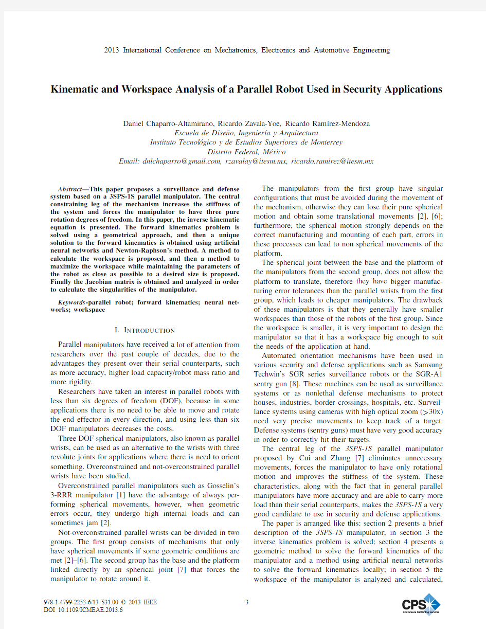
A particular case of the 3SPS-1S manipulator proposed by Cui and Zhang is shown in Figure 1.It has three identical legs,made of two bodies,linked by an actuated prismatic joint.The legs are attached to the platform and the base by spherical joints.It is assumed that the platform and the base are circular,with radii r p and r b respectively,and that the spherical joints of the legs are located along these circumferences.There is also a central passive leg that connects the center of the base to the center of the platform using a spherical
joint.
Figure 1.
Model of the 3SPS-1S parallel wrist.
The general coordinate system xyz is located at the center of the base (O ),and the coordinate system of the platform uvw with origin P is located at the center of the spherical joint of the central
leg.
Figure 2.
Location of points A i and B i .
As shown in ?gure 2,the spherical joints located on the base at points A i have an angle γai with respect to the x axis of the xyz coordinate system,while the joints on the
platform located at points B i have an angle γbi with respect to the u axis of the uvw coordinate system.
III.I NVERSE KINEMATICS
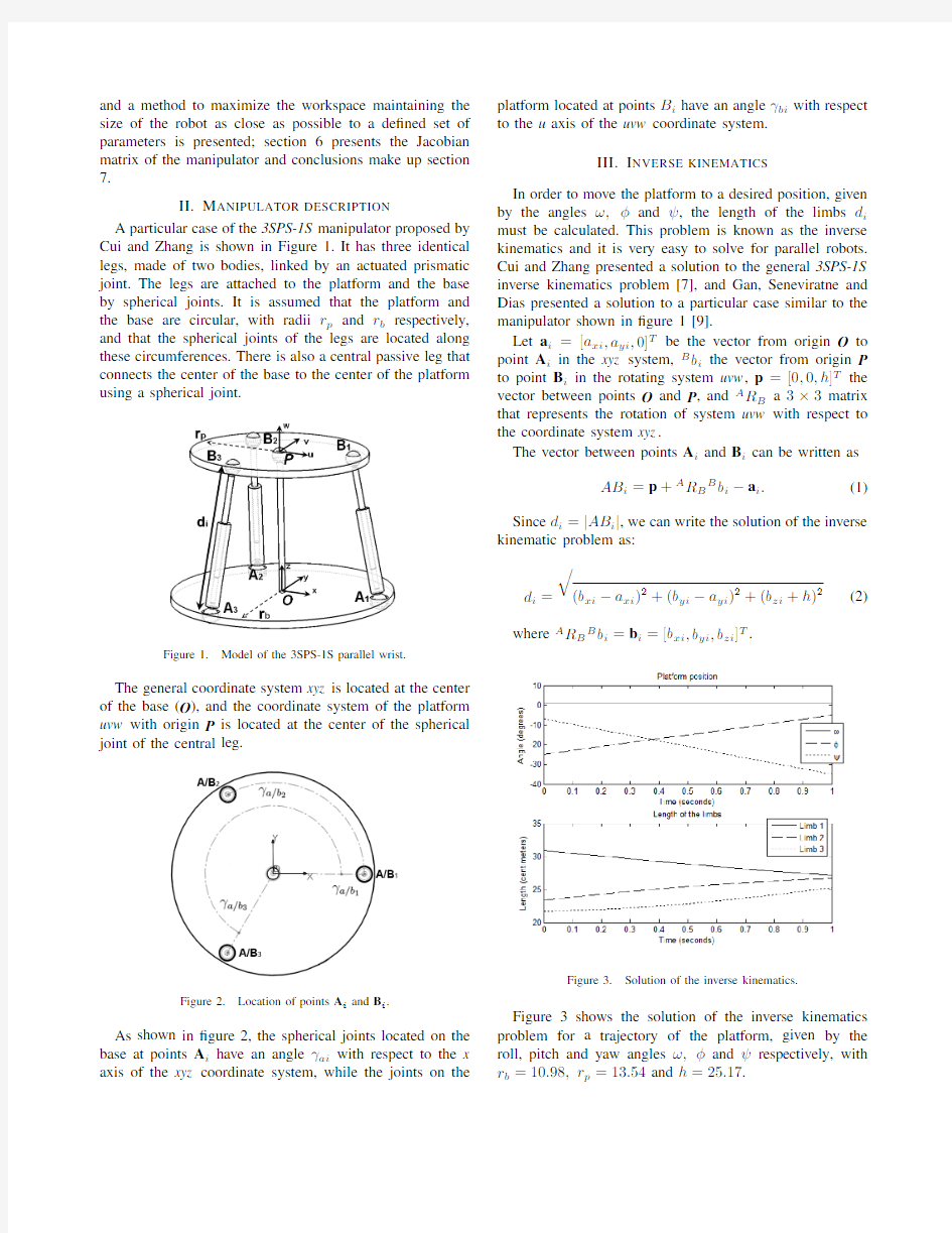
In order to move the platform to a desired position,given by the angles ω,φand ψ,the length of the limbs d i must be calculated.This problem is known as the inverse kinematics and it is very easy to solve for parallel robots.Cui and Zhang presented a solution to the general 3SPS-1S inverse kinematics problem [7],and Gan,Seneviratne and Dias presented a solution to a particular case similar to the manipulator shown in ?gure 1[9].
Let a i =[a xi ,a yi ,0]T be the vector from origin O to point A i in the xyz system,B b i the vector from origin P to point B i in the rotating system uvw ,p =[0,0,h ]T the vector between points O and P ,and A R B a 3×3matrix that represents the rotation of system uvw with respect to the coordinate system xyz .
The vector between points A i and B i can be written as
AB i =p +A R B B b i ?a i .
(1)
Since d i =|AB i |,we can write the solution of the inverse kinematic problem as:
d i =
(b xi ?a xi )2+(b yi ?a yi )2+(b zi +h )2
(2)
where
A
R B B b i =b i =[b xi ,b yi ,b zi ]T
.
Figure 3.
Solution of the inverse kinematics.
Figure 3shows the solution of the inverse kinematics problem for a trajectory of the platform,given by the roll,pitch and yaw angles ω,φand ψrespectively,with r b =10.98,r p =13.54and h =25.17.
IV.F ORWARD KINEMATICS
The forward kinematics problem is to obtain the orien-tation of the platform given the limbs length (d 1,d 2,d 3).As opposed to the inverse kinematics,obtaining the forward kinematics of a parallel robot is a complex task,however,it is important because usually sensors are used to measure the position of the actuators,but not that of the platform;therefore,in order to know the current orientation of the platform given the information provided by the sensors,the forward kinematics must be calculated.A.Geometric method
Gan,Seneviratne and Dias have found an analytical way to solve this problem [9],where they get 8solutions,however,it is also possible to solve the forward kinematics problem using a geometric method.Let S p be a sphere with radius r p and center on point P ,and S i a sphere with radius d i and center on point A i .
The intersection of spheres S p and S i is a circle C i that represents all the possible locations of point B i given the limbs length.
Let d B 12be the distance between points B 1and B 2,d B 13the distance between points B 1and B 3,d B 23the distance between points B 2and B 3,c 1i a point in circle C 1,c 2i a point in circle C 2,and c 3i a point in circle C 3.
If the distance between c 1i and c 2i is d B 12,the distance between c 1i and c 3i is d B 13,and the distance between c 2i and c 3i is d B 23,then those points are a solution to the forward kinematics.Doing this for every point in each circle (given a step size)it is possible to ?nd all the solutions to the forward kinematics
problem.
Figure 4.Unions of points c 1i and c 2i with a distance of d B 12between
them.
Figure 4shows the lines between all points c 1i and c 2i whose distance is equal to d B 12.
Figure 5shows two solutions of the forward kinematics problem obtained with the geometric method.The parame-ters used were:h =25,r b =20,r p =15,d 1=29,d 2=26,d 3=22
.
Figure 5.Solutions of the forward kinematics problem using the geometric method.
B.Local forward kinematics
The method presented by Gan,Seneviratne and Dias,and the geometric method usually ?nd more than one solution to the forward kinematics.The problem is that given an initial orientation of the platform,it is not possible to know which of this solutions is the one that the mechanism will move to;furthermore,if we want to choose only one solution,it must be done manually.
If we want to track the position of the platform at every moment,a method to quickly calculate the forward kinematics based on the current position of the platform is needed.
To solve this problem an arti?cial neural network (ANN)was proposed.The ANN consists of six inputs,three outputs and two hidden layers,one with four neurons and the other with eight neurons.The inputs are the length of the three limbs and the octant of point B i .The outputs are the three angles used to form the rotation matrix A R b .
The ANN is trained with a backpropagation algorithm.A training data set of 1000samples was obtained by varying the angles (one at a time)with a small resolution (1?),and obtaining d 1,d 2and d 3using inverse kinematics.
For any given length of the limbs and initial position of the platform,it is possible to ?nd an approximate solution to the direct kinematics using the trained ANN.Once the approximate solution is found,equation (2)can be written three times (one for each limb)and the system of three non-linear equations can be solved using the Newton-Raphson’s method.
A validation set consisting of 100positions was used to check the method.The results are shown in ?gures 6and 7.Figure 6shows the real trajectory of the platform and the one calculated using forward kinematics with just the initial position known,while ?gure 7shows that the error between both trajectories is negligible.
Figure 6.
Real vs.calculated
trajectory.
Figure 7.Trajectory error.
V.W ORKSPACE ANALYSIS
The inverse kinematics of the manipulator lets us know the length that the actuators must have in order for the platform to reach a certain orientation,however,it is important to know if the manipulator can reach that orientation before trying to move it to that position,thus the reason it is important to analyze the workspace of the manipulator.There are many ways to represent the workspace of orientation parallel robots such as the maximal workspace [10].Let ω,φ,and ψbe three Euler angles representing the orientation of the platform,and A 1the point of interest.The maximal workspace of the 3SPS-1S robot can be de?ned as all the locations of point A i that may be reached with at least one combination of the angles ω,φ,and ψ.
In order for a point to be part of the workspace,three mechanical conditions must be met:max-min limb length,maximum joint angles,and collision between limbs.
Prismatic actuators can contract to a minimum length,and expand to a maximum length.The min-max limb length condition states that the lengths d 1,d 2and d 3must be greater or equal than the minimum length of the actuators,and less or equal than the maximum length of the actuators.Let αij be the angle between limb i and plane j ,being plane 1and 2the base and the platform of the robot respectively,and βj the maximum allowed angle between any limb and plane j .The maximum joint angles condition states that αij must be less or equal than βj .
Let n j be the vector normal to the plane j .The angle αij can be calculated as follows:
αij =π
2?arcsin |n j ·AB i ||n j |·|AB i |
(3)
If the spherical joints have a full range of motion,then
βj =90?,but if the joints have a reduced range of motion,then βj is less than 90?.
The third condition states that if two limbs collide (in-cluding the central mast),the point does not belong to the workspace.Tsai and Lin have proposed a method to ?nd collisions between the legs of a Stewart-Gough platform [11],that can also be used with the 3SPS-1S robot.
Figure 8shows the workspace of a 3SPS-1S parallel robot using the parameters h =20,r b =15,r p =15and βj =90?
.
Figure 8.
Workspace of a 3SPS-1S parallel wrist.
A.Workspace optimization
As mentioned earlier in this paper,the biggest problem of parallel manipulators like the 3SPS-1S parallel wrist is the lack of a big workspace;therefore,optimizing the parameters of the robot in order to maximize the workspace is very important.Nevertheless it is also important for the manipulator to have its parameters (r b ,r p and h )as close as possible to a set of desired parameters,mainly because many times there are size limitations in the location where the manipulator is to be placed.
Different methods to optimize the parameters of parallel robots have been proposed [12]–[16].Some try to maximize
the workspace,others to improve the dynamic behavior or dexterity of the robot and others to reduce the number of singularities.The following method tries to maximize the workspace and at the same time,keep the robot parameters as close as possible to a set of desired parameters.
A genetic algorithm was used to optimize the parameters of the robot.Let Δφ,Δψand Δωbe the range of the pitch,yaw and roll angles respectively,and h d ,r b and r p the desired parameters.The ?tness function can be written as
fitness =a Δφ+b Δψ+c Δω
?d |h ?h d |?e |r b ?r bd |?f |r p ?r pd |
(4)
where a,b.c,d,e and f are weights given to each parameter.The value of these weights depends on the importance of each parameter for a speci?c
application.
Figure 9.Optimized workspace.
Using the desired parameters h d =20,r b =15and r p =15,and the weights a =2,b =2,c =.05,d =10,e =5and f =5,the optimized workspace was calculated.The resulting parameters were h =25.17,r b =10.98and r p =13.54.The optimized workspace (with βj =90?)can be observed in ?gure https://www.360docs.net/doc/b015271540.html,paring it with the original workspace shown in ?gure 8,it is clear that the optimized workspace is bigger than the https://www.360docs.net/doc/b015271540.html,ing the parameters obtained with the optimization method,a sentry gun prototype was design,as shown in ?gure 10.
VI.J ACOBIAN ANALYSIS
While the kinematic analysis gives us a relationship between the position of the platform and the length of the actuators,sometimes it is important to know the relationship between the velocity of the actuated limbs and the angular velocity of the platform,especially while studying the dy-namics of the manipulator.The Jacobian matrix gives us that relationship,and that is why it is important to analyze it.Deriving equation (2)with respect to time we get:
d i ωi ×s i +˙d
i s i =ωp ×b i
(5)
Figure 10.Prototype of the 3SPS-1S robot as a sentry gun.
where b i represents the vector between the origin O and point B i ,s i the unit vector pointing from A i to B i ,ωp the angular velocity of the platform,and ωi the angular velocity of the ith leg.
Dot multiplying both sides of equation (5)by s i gives:
˙d
i =(b i ×s i )ωp (6)
Writing equation (6)three times (one
for each actuator)in matrix form we get:
??˙d 1
˙d 2˙d 3??=???(b 1×s 1)T
(b 2×s 2)T (b 3×s 3)
T ?????ωpx ωpy ωpz
?
?(7)
The matrix multiplying the actuators velocity vector in
equation (7)is the Jacobian matrix of the 3SPS-1S parallel robot.
Whenever the determinant of the Jacobian matrix becomes zero it means the robot presents a singularity at that point.By evaluating the determinant of the Jacobian matrix for each point belonging to the workspace,it is posible to obtain all the singularities presented by the 3SPS-1S
robot.
Figure 11.Singularities of the 3SPS-1S robot.
Figure 11shows the singular con?gurations presented in the 3SPS-1S robot,using the parameters calculated by the genetic algorithm.We can observe that whenever ψand
ωare equal to zero,the robot?nds itself in a singular con?guration.
VII.C ONCLUSIONS
Parallel manipulators can be used as orientation mecha-nisms due to their high stiffness and accuracy.Wrists that have the base and the platform connected by a spherical joint have the advantage of always presenting pure spherical mo-tions;furthermore,they are more tolerant to manufacturing errors than other three DOF parallel wrists.
Although there are both analytical and geometrical meth-ods to calculate the forward kinematics,they return more than one solution and therefore cannot be used to keep track of the orientation of the platform during a trajectory. The local forward kinematics method proposed was able to correctly predict the position of the platform.It is important to correctly train the arti?cial neural network,otherwise the method will likely present some errors.
The optimization method proposed successfully incre-mented the workspace and kept the size of the manipulator not that far from the desired,however,it may be possible to further increment the workspace by changing the?tness function parameters.
It is possible to control the manipulator by using just the kinematic analysis,but while this may work on some applications like a surveillance robot,in other applications like sentry guns a control using the manipulator dynamics is advised,therefore it is important to further analyze this robot.
R EFERENCES
[1] C.Gosselin,“These de doctorat mcgill university,”Ph.D.
dissertation,McGill University,Montr′e al,Canada,1988.
[2]R.Di Gregorio,“Statics and singularity loci of the3-upu
wrist,”IEEE Trans.Robot.,vol.20,no.4,pp.630–635,2001.
[3]R.Di Gregorio,“A new parallel wrist using only revolute
pairs:the3-ruu wrist,”Robotica,vol.19,no.3,pp.305–309, 2001.
[4]J.M.Herv′e and M.Karouia,“A family of novel orientational
3-DOF parallel robots,”in Proc.RoManSy14,Udine,Italy, 2002,pp.359–368.
[5]X.Kong and C.Gosselin,“Type synthesis of3-dof spherical
parallel manipulators based on screw theory,”Journal of Mechanical Design,vol.126,no.1,p.101,2004.
[6] D.Zlatanov,I.Bonev,and C.Gosselin,“Constraint Singu-
larities as C-Space Singularities,”in Proc.8th International Symposium on Advances in Robot Kinematics,Caldes de Malavella,Spain,2002.
[7]G.Cui and Y.Zhang,“Kinetostatic Modeling and Analy-
sis of a New3-DOF Parallel Manipulator,”in Proc.IEEE International Conference on Computational Intelligence and Software Engineering,Dec.2009,pp.1–4.
[8] A.Finn and S.Scheding,Developments and Challenges for
Autonomous Unmanned Vehicles:A Compendium.Springer, 2010.
[9] D.Gan,J.Dias,and L.Seneviratne,“Design and Analytical
Kinematics of a Robot Wrist Based on a Parallel Mechanism,”
in Proc.World Automation Congress,2012,pp.1–6. [10]J.P.Merlet,Parallel Robots,ser.Solid Mechanics and its
Applications.Springer,2006.
[11]K.Tsai and J.Lin,“Determining the compatible orientation
workspace of stewartgough parallel manipulators,”Mecha-nism and Machine Theory,vol.41,no.10,pp.1168–1184, Oct.2006.
[12]S.Huda and Y.Takeda,“Dimensional Synthesis of3-URU
Pure Rotational Parallel Mechanism with Respect to Singu-larity and Workspace,”in Proc.International Federation for the Theory of Mechanisms and Machines World Congress, Besanc?on,2007,pp.1–6.
[13]S.Khan and K.Andersson,“Optimal Design of a6-DoF
Haptic device,”in Proc.IEEE International Conference on Mechatronics,Istambul,2011,pp.713–718.
[14]Y.Lou,G.Liu,and Z.Li,“Randomized optimal design of
parallel manipulators,”IEEE Trans.Autom.Sci.Eng.,vol.5, no.2,pp.223–233,2008.
[15]Z.Wang,G.Wang,S.Ji,Y.Wan,and Q.Yuan,“Optimal
design of a linear delta robot for the prescribed cuboid dex-terous workspace,”in Proc.IEEE International Conference on Robotics and Biomimetics,2007,pp.2183–2188. [16]L.Zhang and Y.Song,“Optimal design of the Delta robot
based on dynamics,”in Proc.IEEE International Conference on Robotics and Automation,2011,pp.336–341.