qinq的cisco配置手册
C H A P T E R
23
Configuring IEEE 802.1Q Tunneling
This chapter describes how to configure IEEE 802.1Q tunneling in Cisco IOS Release 12.2SX.
Note
?
For complete syntax and usage information for the commands used in this chapter, see the Cisco IOS Master Command List, Release 12.2SX, at this URL:
https://www.360docs.net/doc/c211708698.html,/en/US/docs/ios/mcl/122sxmcl/12_2sx_mcl_book.html
?
The WS-X6548-GE-TX, WS-X6548V-GE-TX, WS-X6148-GE-TX, and WS-X6148V-GE-TX switching modules do not support IEEE 802.1Q tunneling.
Tip
For additional information about Cisco Catalyst 6500 Series Switches (including configuration examples and troubleshooting information), see the documents listed on this page:
https://www.360docs.net/doc/c211708698.html,/en/US/products/hw/switches/ps708/tsd_products_support_series_home.html
This chapter consists of these sections:
?Understanding 802.1Q Tunneling, page 23-1
?802.1Q Tunneling Configuration Guidelines and Restrictions, page 23-3?
Configuring 802.1Q Tunneling, page 23-6
Understanding 802.1Q Tunneling
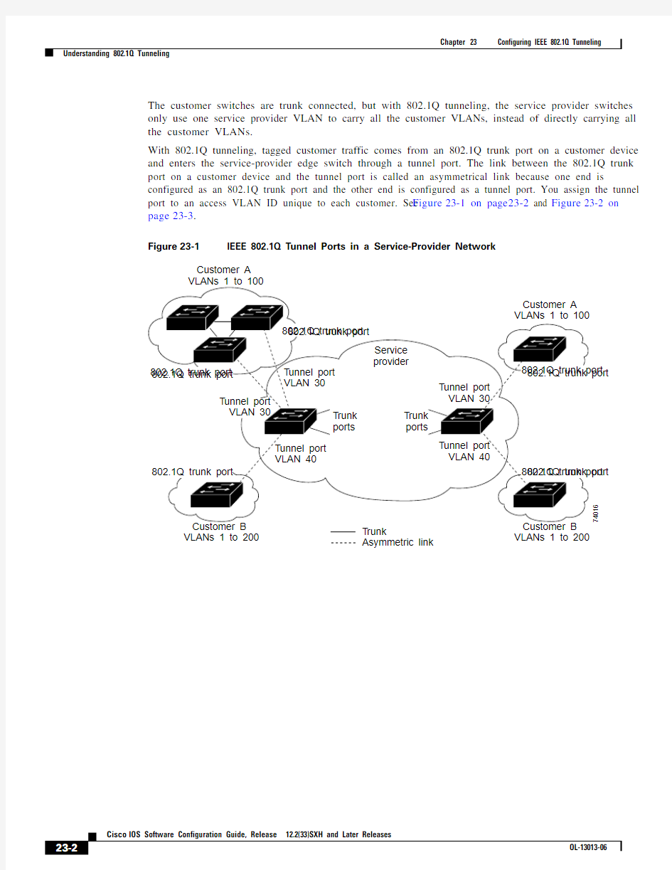
802.1Q tunneling enables service providers to use a single VLAN to support customers who have multiple VLANs, while preserving customer VLAN IDs and keeping traffic in different customer VLANs segregated.
A port configured to support 802.1Q tunneling is called a tunnel port. When you configure tunneling, you assign a tunnel port to a VLAN that you dedicate to tunneling, which then becomes a tunnel VLAN. To keep customer traffic segregated, each customer requires a separate tunnel VLAN, but that one tunnel VLAN supports all of the customer’s VLANs.
802.1Q tunneling is not restricted to point-to-point tunnel configurations. Any tunnel port in a tunnel VLAN is a tunnel entry and exit point. An 802.1Q tunnel can have as many tunnel ports as are needed to connect customer switches.
Chapter23 Configuring IEEE 802.1Q Tunneling Understanding 802.1Q Tunneling
Chapter23 Configuring IEEE 802.1Q Tunneling
802.1Q Tunneling Configuration Guidelines and Restrictions
Chapter23 Configuring IEEE 802.1Q Tunneling 802.1Q Tunneling Configuration Guidelines and Restrictions
?Dedicate one VLAN for each tunnel.
?Assign only tunnel ports to VLANs used for tunneling.
?Trunks require no special configuration to carry tunnel VLANs.
?Tunnel ports are not trunks. Any commands to configure trunking are inactive while the port is configured as a tunnel port.
?Tunnel ports learn customer MAC addresses.
?We recommend that you use ISL trunks to carry tunnel traffic between devices that do not have tunnel ports. Because of the 802.1Q native VLAN feature, using 802.1Q trunks requires that you be
very careful when you configure tunneling: a mistake might direct tunnel traffic to a non-tunnel port.
?By default, the native VLAN traffic of a dot1q trunk is sent untagged, which cannot be
double-tagged in the service provider network. Because of this situation, the native VLAN traffic
might not be tunneled correctly. Be sure that the native VLAN traffic is always sent tagged in an
asymmetrical link. To tag the native VLAN egress traffic and drop all untagged ingress traffic, enter
the global vlan dot1q tag native command.
?Configure jumbo frame support on tunnel ports:
–See the “Configuring Jumbo Frame Support” section on page9-10.
–Take note of the modules listed in the “Configuring Jumbo Frame Support” section that do not support jumbo frames.
?Jumbo frames can be tunneled as long as the jumbo frame length combined with the 802.1Q tag does not exceed the maximum frame size.
?Because tunnel traffic has the added ethertype and length field and retains the 802.1Q tag within the switch, the following restrictions exist:
–The Layer 3 packet within the Layer 2 frame cannot be identified in tunnel traffic.
–Layer 3 and higher parameters cannot be identified in tunnel traffic (for example, Layer 3
destination and source addresses).
–Because the Layer 3 addresses cannot be identified within the packet, tunnel traffic cannot be routed.
–The switch can provide only MAC-layer filtering for tunnel traffic (VLAN IDs and source and destination MAC addresses).
–The switch can provide only MAC-layer access control and QoS for tunnel traffic.
–QoS cannot detect the received CoS value in the 802.1Q 2-byte Tag Control Information field.
?On an asymmetrical link, the Cisco Discovery Protocol (CDP) reports a native VLAN mismatch if the VLAN of the tunnel port does not match the native VLAN of the 802.1Q trunk. The 802.1Q
tunnel feature does not require that the VLANs match. Ignore the messages if your configuration
requires nonmatching VLANs.
?Asymmetrical links do not support the Dynamic Trunking Protocol (DTP) because only one port on the link is a trunk. Configure the 802.1Q trunk port on an asymmetrical link to trunk unconditionally.
?The 802.1Q tunneling feature cannot be configured on ports configured to support private VLANs.
?The following Layer 2 protocols work between devices connected by an asymmetrical link:
–CDP
–UniDirectional Link Detection (UDLD)
–Port Aggregation Protocol (PAgP)
–Link Aggregation Control Protocol (LACP)
Chapter23 Configuring IEEE 802.1Q Tunneling
802.1Q Tunneling Configuration Guidelines and Restrictions
?Spanning-tree BPDU filtering is enabled automatically on tunnel ports.
?CDP is automatically disabled on tunnel ports.
?VLAN Trunk Protocol (VTP) does not work between the following devices:
–Devices connected by an asymmetrical link
–Devices communicating through a tunnel
Note VTP works between tunneled devices if Layer 2 protocol tunneling is enabled. See
Chapter24, “Configuring Layer 2 Protocol Tunneling,” for configuration details.
?To configure an EtherChannel as an asymmetrical link, all ports in the EtherChannel must have the same tunneling configuration. Because the Layer 3 packet within the Layer 2 frame cannot be
identified, you must configure the EtherChannel to use MAC-address-based frame distribution.
The following configuration guidelines are required for your Layer 2 protocol tunneling configuration:
?On all the service provider edge switches, PortFast BPDU filtering must be enabled on the 802.1Q tunnel ports as follows:
Router(config-if)# spanning-tree bpdufilter enable
Router(config-if)# spanning-tree portfast
Note Spanning-tree BPDU filtering is enabled automatically on tunnel ports.
?At least one VLAN must be available for native VLAN tagging (vlan dot1q tag native option). If you use all the available VLANs and then try to enable the vlan dot1q tag native option, the option
will not be enabled.
?On all the service provider core switches, tag native VLAN egress traffic and drop untagged native VLAN ingress traffic by entering the following command:
Router(config)# vlan dot1q tag native
?On all the customer switches, either enable or disable the global vlan dot1q tag native option.
Note If this option is enabled on one switch and disabled on another switch, all traffic is dropped;
all customer switches must have this option configured the same on each switch.
The following configuration guidelines are optional for your Layer 2 protocol tunneling configuration:
?Because all the BPDUs are being dropped, spanning tree PortFast can be enabled on Layer 2 protocol tunnel ports as follows:
Router(config-if)# spanning-tree portfast trunk
?If the service provider does not want the customer to see its switches, CDP should be disabled on the 802.1Q tunnel port as follows:
Router(config-if)# no cdp enable
Chapter 23 Configuring IEEE 802.1Q Tunneling
Configuring 802.1Q Tunneling
Configuring 802.1Q Tunneling
These sections describe 802.1Q tunneling configuration:
?Configuring 802.1Q Tunnel Ports, page 23-6
?
Configuring the Switch to Tag Native VLAN Traffic, page 23-7
Caution
Ensure that only the appropriate tunnel ports are in any VLAN used for tunneling and that one VLAN is used for each tunnel. Incorrect assignment of tunnel ports to VLANs can forward traffic inappropriately.
Configuring 802.1Q Tunnel Ports
To configure 802.1Q tunneling on a port, perform this task:
This example shows how to configure tunneling on port 4/1 and verify the configuration:
Router# configure terminal
Router(config)# interface fastethernet 4/1
Router(config-if)# switchport mode dot1q-tunnel Router(config-if)# end
Router# show dot1q-tunnel interface
Command
Purpose
Step 1Router(config)# interface type 1slot/port 1.
type = fastethernet , gigabitethernet , or tengigabitethernet
Selects the LAN port to configure.
Step 2
Router(config-if)# switchport
Configures the LAN port for Layer 2 switching.
?
You must enter the switchport command once without any keywords to configure the LAN port as a Layer 2 interface before you can enter additional switchport commands with keywords.?
Required only if you have not entered the
switchport command already for the interface.
Step 3Router(config-if)# switchport mode dot1q-tunnel Configures the Layer 2 port as a tunnel port. Step 4Router(config-if)# end
Exits configuration mode.Step 5
Router# show dot1q-tunnel [{interface type 1 interface-number }]Verifies the configuration.
Chapter23 Configuring IEEE 802.1Q Tunneling
Configuring 802.1Q Tunneling
Configuring the Switch to Tag Native VLAN Traffic
The vlan dot1q tag native command is a global command that configures the switch to tag native VLAN
traffic, and admit only 802.1Q tagged frames on 802.1Q trunks, dropping any untagged traffic, including
untagged traffic in the native VLAN.
On ports where you enter the no switchport trunk native vlan tag interface command, the function of
the vlan dot1q tag native global command is disabled.
These sections describe how to configure the switch to tag native VLAN traffic:
?Configuring the Switch to Tag Native VLAN Traffic Globally, page23-7
?Configuring Ports Not to Tag Native VLAN Traffic, page23-7
Configuring the Switch to Tag Native VLAN Traffic Globally
With Release12.2(33)SXH and later releases, to configure the switch to tag traffic in the native VLAN
globally, perform this task:
Command Purpose
Step1Router(config)# vlan dot1q tag native Configures the switch to tag native VLAN traffic
globally.
Step2Router(config)# end Exits configuration mode.
Step3Router# show vlan dot1q tag native | include globally Verifies the configuration.
This example shows how to configure the switch to tag native VLAN traffic and verify the configuration:
Router# configure terminal
Router(config)# vlan dot1q tag native
Router(config)# end
Router# show vlan dot1q tag native | include globally
dot1q native vlan tagging is enabled globally
Router(config)#
Configuring Ports Not to Tag Native VLAN Traffic
When the switch is configured to tag native VLAN traffic globally, you can disable native VLAN tagging
on a per-port basis.
To configure a port not to tag traffic in the native VLAN, perform this task:
Command Purpose
Step1Router(config)# interface type1slot/port Selects the LAN port to configure.
Step2Router(config-if)# switchport Configures the LAN port for Layer 2 switching.
?You must enter the switchport command once
without any keywords to configure the LAN port as
a Layer2 interface before you can enter additional
switchport commands with keywords.
?Required only if you have not entered the
switchport command already for the port.
Chapter 23 Configuring IEEE 802.1Q Tunneling
Configuring 802.1Q Tunneling
Note
The switchport trunk native vlan tag interface command does not enable native VLAN tagging unless the switch is configured to tag native VLAN traffic globally.
This example shows how to configure Gigabit Ethernet port 1/4 to tag traffic in the native VLAN and verify the configuration:
Router# configure terminal
Router(config)# interface gigabitethernet 1/4
Router(config-if)# switchport trunk native vlan tag Router(config-if)# end
Router# show interface gigabitethernet 1/4 switchport | include tagging Administrative Native VLAN tagging: enabled Operational Native VLAN tagging: disabled Router#
Tip
For additional information about Cisco Catalyst 6500 Series Switches (including configuration examples and troubleshooting information), see the documents listed on this page:
https://www.360docs.net/doc/c211708698.html,/en/US/products/hw/switches/ps708/tsd_products_support_series_home.html
Step 3Router(config-if)# no switchport trunk native vlan tag
Configures the Layer 2 port not to tag native VLAN traffic.
Step 4Router(config-if)# end
Exits configuration mode.Step 5
Router# show interface type 1 interface-number | include tagging Verifies the configuration.
1.
type = fastethernet , gigabitethernet , or tengigabitethernet
Command
Purpose
CISCO路由器配置手册
第一章路由器配置基础 一、基本设置方式 一般来说,可以用5种方式来设置路由器: 1.Console口接终端或运行终端仿真软件的微机; 2.AUX口接MODEM,通过电话线与远方的终端或运行终端仿真软件的微机相连; 3.通过Ethernet上的TFTP服务器; 4.通过Ethernet上的TELNET程序; 5.通过Ethernet上的SNMP网管工作站。 但路由器的第一次设置必须通过第一种方式进行,此时终端的硬件设置如下: 波特率:9600 数据位:8 停止位:1 奇偶校验: 无 二、命令状态 1. router> 路由器处于用户命令状态,这时用户可以看路由器的连接状态,访问其它网络和主机,但不能看到和更改路由器的设置内容。
2. router# 在router>提示符下键入enable,路由器进入特权命令状态router#,这时不但可以执行所有的用户命令,还可以看到和更改路由器的设置内容。 3. router(config)# 在router#提示符下键入configure terminal,出现提示符router(config)#,此时路由器处于全局设置状态,这时可以设置路由器的全局参数。 4. router(config-if)#; router(config-line)#; router(config-router)#;… 路由器处于局部设置状态,这时可以设置路由器某个局部的参数。 5. > 路由器处于RXBOOT状态,在开机后60秒内按ctrl-break可进入此状态,这时路由器不能完成正常的功能,只能进行软件升级和手工引导。 6. 设置对话状态 这是一台新路由器开机时自动进入的状态,在特权命令状态使用SETUP命令也可进入此状态,这时可通过对话方式对路由器进行设置。 三、设置对话过程 1.显示提示信息 2.全局参数的设置 3.接口参数的设置 4.显示结果 利用设置对话过程可以避免手工输入命令的烦琐,但它还不能完全代替手工设置,一些特殊的设置还必须通过手工输入的方式完成。 进入设置对话过程后,路由器首先会显示一些提示信息: --- System Configuration Dialog --- At any point you may enter a question mark '?' for help. Use ctrl-c to abort configuration dialog at any prompt. Default settings are in square brackets '[]'. 这是告诉你在设置对话过程中的任何地方都可以键入“?”得到系统的帮助,按ctrl-c 可以退出设置过程,缺省设置将显示在‘[]’中。然后路由器会问是否进入设置对话:
Cisco+6509配置手册
Catalyst 6509 交换机 配置手册 version 1.0.0 中望商业机器有限公司? 1995, 2001 Chinaweal Business Machinery CO. LTD All Rights Reserve
目录 1基础配置 (1) 1.1建立到控制台的连接 (1) 1.2配置交换机的地址 (2) 1.3配置Ethernet 口 (3) 1.4配置交换机的全局参数 (4) 1.5测试网络的连通性 (4) 2其它参数的配置 (5) 2.1配置Login Banner (5) 2.2配置DNS (6) 2.3配置CDP协议 (7) 3VLAN的配置 (8) 3.1配置VTP协议(VLAN Trunk Protocol) (9) 3.2配置VLAN (10) 3.2.1创建VLAN (10) 3.3将交换端口配置到VLAN中 (10) 3.4配置VLAN Trunks (12) 3.5在MSFC上配置IP InterVLAN路由 (13) 3.5.1从Console口进入MSFC (13) 3.5.2通过T elnet Session 进入MSFC 模块 (13) 3.5.3在MSFC上配置IP InterVLAN路由 (14) 3.6配置HSRP协议 (14) 3.7配置以太通道 (16)
1 基础配置 1.1 建立到控制台的连接 在进行配置和将交换机接入网络前必须通过控制台来进入交换机的CLI,对交换机进行配置。在进入CLI后,通过命令enable进入到privileged 模式。 通过以下步骤将终端连接到交换机的控制口 例如: <... output truncated ...> Cisco Systems Console Enter password: Console> enable Enter password: Console> (enable) - 1 -
Cisco设备的基本配置命令
switch> 用户模式 1:进入特权模式 enable switch> enable switch# 2:进入全局配置模式 configure terminal switch> enable switch#c onfigure terminal switch(conf)# 3:交换机命名 hostname aptech2950 以aptech2950为例 switch> enable switch#c onfigure terminal switch(conf)#hostname aptch-2950 aptech2950(conf)# 4:配置使能口令 enable password cisco 以cisco为例 switch> enable switch#c onfigure terminal switch(conf)#hostname aptch2950 aptech2950(conf)# enable password cisco 5:配置使能密码 enable secret ciscolab 以cicsolab为例 switch> enable switch#c onfigure terminal switch(conf)#hostname aptch2950 aptech2950(conf)# enable secret ciscolab 6:设置虚拟局域网vlan 1 interface vlan 1 switch> enable switch#c onfigure terminal switch(conf)#hostname aptch2950 aptech2950(conf)# interface vlan 1 aptech2950(conf-if)#ip address 192.168.1.1 255.255.255.0 配置交换机端口ip 和子网掩码 aptech2950(conf-if)#no shut 是配置处于运行中aptech2950(conf-if)#exit aptech2950(conf)#ip default-gateway 192.168.254 设置网关地址 7:进入交换机某一端口 interface fastehernet 0/17 以17端口为例switch> enable switch#c onfigure terminal switch(conf)#hostname aptch2950 aptech2950(conf)# interface fastehernet 0/17 aptech2950(conf-if)#
思科交换机配置维护手册
思科交换机配置维护手册
目录
一、端口配置 1.1 配置一组端口 当使用interface range命令时有如下的规则: ?有效的组范围: o vlan从1 到4094 o fastethernet槽位/{first port} - {last port}, 槽位为0 o gigabitethernet槽位/{first port} - {last port},槽位为0 o port-channel port-channel-number - port-channel-number, port-channel号从1到64 ?端口号之间需要加入空格,如:interface range fastethernet 0/1 – 5是有效的,而interface range fastethernet 0/1-5是无效的. ?interface range命令只能配置已经存在的interface vlan ?所有在同一组的端口必须是相同类别的。
见以下例子: Switch# configure terminal Switch(config)# interface range fastethernet0/1 - 5 Switch(config-if-range)# no shutdown 以下的例子显示使用句号来配置不同类型端口的组: Switch# configure terminal Switch(config)# interface range fastethernet0/1 - 3, gigabitethernet0/1 - 2 Switch(config-if-range)# no shutdown 1.2 配置二层端口 1.2.1 配置端口速率及双工模式
Cisco交换机配置手册
2950交换机 简明配置维护手册
目录 说明 (3) 产品特性 (3) 配置端口 (4) 配置一组端口 (4) 配置二层端口 (6) 配置端口速率及双工模式 (6) 端口描述 (7) 监控及维护端口 (8) 监控端口和控制器的状态 (8) 刷新、重置端口及计数器 (10) 关闭和打开端口 (10) 配置VLAN (11) 理解VLAN (11) 可支持的VLAN (12) 配置正常范围的VLAN (12) 生成、修改以太网VLAN (13) 删除VLAN (14) 将端口分配给一个VLAN (15) 配置VLAN Trunks (16) 使用STP实现负载均衡 (19) 配置Cluster (23)
说明 本手册只包括日常使用的有关命令及特性,其它未涉及的命令及特性请参考英文的详细配置手册。 产品特性 2950是只支持二层的交换机 支持VLAN ?到250 个VLAN ?支持VLAN ID从1到4094(IEEE 802.1Q 标准) ?支持ISL及IEEE 802.1Q封装 安全 ?支持IOS标准的密码保护 ?支持标准及扩展的访问列表来定义安全策略 ?支持基于VLAN的访问列表 监视 ?交换机LED指示端口状态 ?SPAN及远端SPAN (RSPAN) 可以监视任何端口或VLAN的流量 ?内置支持四组的RMON监控功能(历史、统计、告警及事件)
配置端口 配置一组端口 当使用interface range命令时有如下的规则: ?有效的组范围: o vlan从1 到4094 o fastethernet槽位/{first port} - {last port}, 槽位为0 o gigabitethernet槽位/{first port} - {last port},槽位为0 o port-channel port-channel-number - port-channel-number, port-channel号从1到64 ?端口号之间需要加入空格,如:interface range fastethernet 0/1 – 5是有效的,而interface range fastethernet 0/1-5是无效的. ?interface range命令只能配置已经存在的interface vlan ?所有在同一组的端口必须是相同类别的。
思科交换机6509配置实例(双机热备)
CISCO 6509配置手册 1.设置时间 switch#config t switch(config)# clock timezone GMT 8 ;配置时区 switch(config)# clock set 13:30:21 31 JAN 2004 ;配置交换机时间2.设置主机名及密码 Switch#congfig t Switch(config)#hostname 6509a //配置交换机名称6509a(config)#enable password cisco //配置用户密码 6509a (config)#enable secret cisco //配置安全密码 6509a (config-line)#line vty 0 15 //配置远程访问密码6509a (config-line)#login 6509a (config-line)#password cisco 6509a (config-line)#login 6509a (config-line)#^z 6509a #show running-config //查看配置信息 6509a #copy running-config startup-config 6509a #show startup-config 6509a #show bootvar 6509a #dir bootflash: 6509a #copy system:running-config nvram:startup-config 6509a #show fabric status 6509a #show hardware 3.配置vlan 6509a #config t 6509a (config)#vlan 301 6509a (config-vlan)# name hexinxitong 6509a (config)#vlan 302 6509a (config-vlan)# name callcenter 6509a (config)#vlan 303 6509a (config-vlan)# name kuaijicaiwu
cisco 6509配置手册
cisco 6509交换机配置手册 一个经典配置包括Catalyst6509 4006交换机配置方案 拓扑图如下: 一、 Catalyst 6509交换机配置方案 1.1、配置6509二层交换 Console> (enable) set system name bg-sw-01 /设备名称Bg-sw-01> (enable) set password Enter old password: Enter new password: test /设备口令 Retype new password: test Bg-sw-01> (enable) set enablepass Enter old password: Enter new password: test /设备口令 Retype new password: test
Bg-sw-01> (enable) set banner motd % Welcome to the c6509 in the office % / 提示文本 Bg-sw-01> (enable) set interface sc0 10.234.180.21 255.255.255.0 /设置管理接口 #sh int Bg-sw-01> (enable) set ip route default 10.234.180.234 /设置默认网关 #sh ip route Bg-sw-01> (enable) set vtp mode server /设置VTP模式 #sh vtp domain Bg-sw-01> (enable) set vtp domain Core_Net /设置VTP域名 Bg-sw-01> (enable) set vlan 31 name ZhongSanLu /创建VLAN #sh vlan Bg-sw-01> (enable) set vlan 32 name YiYang Bg-sw-01> (enable) set vlan 33 name JianXiu Bg-sw-01> (enable) set vlan 34 name RaoDian Bg-sw-01> (enable) set vlan 35 name JinSanLou Bg-sw-01> (enable) set vlan 36 name WuZi Bg-sw-01> (enable) set port channel 1/1-2 on /设置Channel #sh port channel Bg-sw-01> (enable) set trunk 1/1 on dot1q 1-1005 Bg-sw-01> (enable) set trunk 2/2 on dot1q 1-1005 /设置trunk口 #sh trunk # Bg-sw-01> (enable) set trunk 2/3 on dot1q 1-1005 Bg-sw-01> (enable) set trunk 2/4 on dot1q 1-1005 Bg-sw-01> (enable) set trunk 2/5 on dot1q 1-1005 Bg-sw-01> (enable) set trunk 2/6 on dot1q 1-1005 Bg-sw-01> (enable) set trunk 2/7 on dot1q 1-1005 Bg-sw-01> (enable) set spantree root 1-40 dia 4 /设为spantree的根#sh spantree Bg-sw-01> (enable) set spantree portfast 1/1-2 enable /设spantree端口快速启用Bg-sw-01> (enable) set spantree portfast 2/1-8 enable Bg-sw-01> (enable) set spantree uplinkfast enable /设spantree端口快速切换 Bg-sw-01> (enable) set spantree backbonefast enable /设spantree端口快速定位根 1.2、配置路由
Cisco AP配置手册
Cisco AP 配置手册 (2)设置工作模式 工作模式也即工作角色,主要是指AP 工作在中继/转发模式或者是根模式。在中继/转发模式下,AP 无需与有线LAN 进行连接,但它必须与一个连接有LAN 的AP 命令,参数说明如下: repeater-指定AP 为转发/中继模式 root-指定AP 为根模式,参数fallback shutdown 指定了当主 ethernet 口停用时关闭AP ;而fallback repeater 指定了AP 当在主ethernet 口停用时工作在repeater 模式下。 (3)、设置发射功率 客户端功率设置: 配置客户端发射功率,客户端将以该设置的功率与AP 进行802.11无线通信,当
可以使用CCK功率等级,CCK(补充编码键控)模式下可以由IEEE802.11b和IEEE802.11g设备来支持,而OFDM模式下可以由IEEE802.11a和IEEE802.11g 设备来支持。 举例说明: 配置指定客户端发射功率为20mW: ap(config-if)# power client 20 配置指定本地AP发射功率为20mW: ap(config-if)# power local 20 speed {[1.0] [2.0] [5.5]…中可选参数的设置是指允许AP使用非基本设置,即AP只以这些速率发送单播包;
speed [basic-1.0] [basic-2.0]…中可选参数的设置是指允许AP使用基本设置来发送所有单播和组播数据包。至少一个AP的速率必须被配置为基本设置。[rang]可选参数是指设置数据速率以获得最佳范围。 [throughput]可选参数是指设置数据率以获得最佳吞吐量。 [default]可选参数是指将数据率设置为默认。 注意: IEEE802.11g无线功率在上升至100mW时,可以达到1M,2M,5.5M和11M的速度;对于6M,9M,12M,18M,24M,36M,48M和54Mbps数据速率,可以在802.11g 最大无线功率为30mW时实现。 举例说明: 设置AP无线接口的数据速率以获得最佳吞吐量: ap(config-if)# speed throughput 设置AP无线接口同时支持基本速率和非基本速率的设置: ap(config-if)# speed basic-1.0 2.0 5.5 11.0 number参数是指信道编号,除了不同的IEEE802.11系列不同标准的信道有所差异外,不同的管制域所允许的信道也有所不同。 frequency参数是指无线信道的中心频率,有效的频率取决于每个管制域中所允许的信道。 least-congested参数是指启用或禁用扫描闲置信道,并使用该信道与客户端进行无线通信。 如下列表中所示2.4-GHz Radios (包括802.11b和802.11g)信道和中心频率:如下列表中所示5-GHz Radioswy信道和中心频率:
配置Cisco 6509-E VSS完整步骤
00:00:05: %SYS-3-LOGGER_FLUSHING: System pausing to ensure console debugging output. Firmware compiled 13-Aug-10 11:12 by integ Build [100] Earl Card Index= 259 00:00:05: %PFREDUN-6-ACTIVE: Initializing as ACTIVE processor for this switch 00:00:07: %SYS-SP-3-LOGGER_FLUSHING: System pausing to ensure console debugging output. 00:00:05: %SYS-3-LOGGER_FLUSHED: System was paused for 00:00:00 to ensure console debugging output. 00:00:07: %OIR-SP-6-CONSOLE: Changing console ownership to route processor System Bootstrap, Version 12.2(17r)SX7, RELEASE SOFTWARE (fc1) Technical Support: https://www.360docs.net/doc/c211708698.html,/techsupport Copyright (c) 2009 by cisco Systems, Inc. Cat6k-Sup720/RP platform with 1048576 Kbytes of main memory Download Start !!!!!!!!!!!!!!!!!!!!!!!!!!!!!!!!!!!!!!!!!!!!!!!!!!!!!!!!!!!!!!!!!!!!!!!!!!!!!!!!!!!!!!!!!!!!!!!!!!!!!!!!!!!!!!!!!!!!!!!!! !!!!!!!!!!!!!!!!!!!!!!!!!!!!!!!!!!!!!!!!!!!!!!!!!!!!!!!!!!!!!!!!!!!!!!!!!!!!!!!!!!!!!!!!!!!!!!!!!!!!!!!!!!!!!!!!!!!!!!!!! !!!!!!!!!!!!!!!!!!!!!!!!!!!!!!!!!!!!!!!!!!!!!!!!!!!!!!!!!!!!!!!!!!!!!!!!!!!!!!!!!!!!!!!!!!!!!!!!!!!!!!!!!!!!!!!!!!!!!!!!! !!!!!!!!!!!!!!!!!!!!!!!!!!!!!!!!!!!!!!!!!!!!!!!!!!!!!!!!!!!!!!!!!!!!!!!!!!!!!!!!!!!!!!!!!!!!!!!!!!!!!!!!!!!!!!!!!!!!!!!!! !!!!!!!!!!!!!!!!!!!!!!!!!!!!!!!!!!!!!!!!!!!!!!!!!!!!!!!!!!!!!!!!!!!!!!!!!!!!!!!!!!!!!!!!!!!!!!!!!!!!!!!!!!!!!!!!!!!!!!!!! !!!!!!!!!!!!!!!!!!!!!!!!!!!!!!!!!!!!!!!!!!!!!!!!!!!!!!!!!!!!!!!!!!!!!!!!!!!! Download Completed! Booting the image. Self decompressing the image : ############################################################################### ############################################################################### ############################################################ [OK] Restricted Rights Legend Use, duplication, or disclosure by the Government is subject to restrictions as set forth in subparagraph (c) of the Commercial Computer Software - Restricted
cisco2800配置手册
《Cisco 2801路由器》用户配置手册 约定 在介绍重要的术语和概念时,或许以粗体显示。正文所包含的命令以常体显示,用于实例的所有名称或地址亦是这样,同时不应该用到你的实际网络中。配置你的系统时不要一字不差地输入名称或地址。最后,在某些例子中,在命令要求IP地址作为参数的地方,IP地址可能以xx.xx.xx.xx或https://www.360docs.net/doc/c211708698.html,.dd这种方式来表示。实际上,配置你的系统时永远不会用到这些字符串。本文的约定指出 你应该把指明的地方替换成适当的IP地址。 1.本文档覆盖的东西有好几种方法可用来配置Cisco路由器。配置可以由TFTP服务器通过网络来完成;可以通过启动时提供的菜单界面来完成;并且可以由运行setup命令所提供的菜单界面来完成;还可以由保存到内存中的配置来完成。本手册不会覆盖这几种方法,它仅覆盖由IOS命令行界面来进行的配置。 注意:本手册不覆盖路由器与它要路由的网络在物理上的连接,它仅覆盖操作系统配置。 1.1使用命令行的原因使用命令行界面而不使用菜单驱动界面的原因有两个: 一个是速度。一旦你已花费时间去了解命令行命令,就可以比通过使用菜单更加迅速地完成许多操作。基本上,相对于菜单的所有命令行来说,这点是真的。对于了解Cisco IOS的命令行界面来说它是特别有效的东西,而Cisco IOS是跨越一切Cisco路由器的标准。 其次,可以配置单个接口而不必中断其它接口上的服务。根据定义,路由器有多个接口。例如,在 Cisco 7200系列路由器中,路由器有多个端口,每个端口有几个可热插拔模块。这些模块能够经由命令行来单独配置是一种颇有价值的技术。 1.2 文档结构本文的第一部分将介绍IOS的命令模式和Cisco路由器基本配置所必需的命令。文档的第二部分将在个案研究里示范这些命令的用法。个案研究是由本文作者完成的实际配置。 2.准备开始初时,你或许会通过终端来配置你的路由器。如果路由器已经配置过,而且至少一个端口已经用IP地址配置好,同时它与网络有物理连接的话,你也许能够telnet到路由器,通过网络来配置它。如果路由器未曾做过配置,那么你将不得不用终端和一条串口电缆直接和它连接。对于任何一台Windows主机来说,你都可以用超级终端(Hyperterminal)容易地连接路由器。把串口电缆插入PC机上的串口(COM),另一端插入Cisco路由器上的控制台端口。启动超级终端,告诉它所用的COM 口并点击OK。把连接速率设置为9600波特,点击OK。如果路由器未开机,启动它。 如果你想由Linux主机来配置路由器,要运行Seyon或Minicom。至少它们中的一个,也许两个都在你的Linux分发套件中。 通常,你需要敲Enter(回车)键来观看路由器所作的提示。如果路由器未做过配置,它看起来象这样: Cisco2801> Cisco2801 为主机名称原始名称为(Router)为了更好的管理和使用特更改为(Cisco2801) 你要配置路由器就必须进入特权模式。你可以通过使用enable命令来做到这点。特权模式通常是口令保护,除非路由器未配置好。你有无口令保护特权模式的选择,但极力推荐你选择有口令保护的特权模式。在你运行命令enable并提供口令之后,你就会进入特权模式。 为了帮助用户看清所处的模式,每次进入不同的模式,命令行的提示都会发生改变。当你从非特权模式切换到特权模式时,提示由: Cisco2801> 变成 Cisco2801# 配置实例 用超级终端连接到到Cisco设备上
Cisco6500系列交换机配置
65xx系列交换机配置(Native IOS) 1. 6509介绍 Cisco Catalyst 6500系列交换机提供3插槽、6插槽、9插槽和13插槽的机箱,以及多种集成式服务模块,包括数千兆位网络安全性、内容交换、语音和网络分析模块。 Catalyst 6500系列中的所有型号都使用了统一的模块和操作系统软件,形成了能够适应未来发展的体系结构,由于能提供操作一致性,因而能提高IT基础设施的利用率,并增加投资回报。从48端口到576端口的10/100/1000以太网布线室到能够支持192个1Gbps或32个10Gbps骨干端口,提供每秒数亿个数据包处理能力的网络核心,Cisco Catalyst 6500系列能够借助冗余路由与转发引擎之间的故障切换功能提高网络正常运行时间。 提高网络正常运行时间,提高网络弹性。提供数据包丢失保护,能够从网络故障中快速恢复。能够在冗余控制引擎间实现快速的1~3秒状态故障切换。 提供可选的高性能Cisco Catalyst 6500系列Supervisor Engine 720、无源背板、多引擎的冗余;并可利用Cisco EtherChannel?技术、IEEE 802.3ad链路汇聚、IEEE802.1s/w和热备份路由器协议/虚拟路由器冗余协议(HSRP/VRRP)达到高可用性不需要部署外部设备,直接在6500机箱内部署集成式的千兆位的网络服务模块,以简化网络管理,降低网络的总体成本。这些网络服务模块包括:
l 千兆位防火墙模块--提供接入保护 l 高性能入侵检测系统(IDS)模块--提供入侵检测保护 l 千兆位网络分析模块--提供可管理性更高的基础设施和全面的远程超级(RMON)支持 l 高性能SSL模块--提供安全的高性能电子商务流量 l 千兆位VPN和基于标准的IP Security(IPSec)模块--降低的互联网和内部专网的连接成本。 集成式内容交换模块(CSM)能够为Cisco Catalyst 6500系列提供功能丰富的高性能的服务器和防火墙网络负载平衡连接,以提高网络基础设施的安全性、可管理性和强大控制基于网络的应用识别(NBAR)等软件特性可提供增强网络管理和QoS控制机制。 利用分布式Cisco Express Forwarding dCEF720平台提供400Mpps交换性能。支持多种Cisco Express Forwarding(CEF)实现方式和交换矩阵速率。 多协议第3层路由支持满足了传统的网络要求,并能够为企业网络提供平滑的过渡机制。支持IPv6,并提供高性能的IPv6服务。提供MPLS及MPLS/VPN的支持,并具有
思科交换机基本配置(非常详细)
cisco交换机基本配置 1.Cisco IOS简介 Cisco Catalyst系列交换机所使用的操作系统是IOS(Internetwork Operating System,互联网际操作系统)或COS(Catalyst Operating System),其中以IOS使用最为广泛,该操作系统和路由器所使用的操作系统都基于相同的内核和shell。 IOS的优点在于命令体系比较易用。利用操作系统所提供的命令,可实现对交换机的配置和管理。Cisco IOS操作系统具有以下特点: (1)支持通过命令行(Command-Line Interface,简称CLI)或Web界面,来对交换机进行配置和管理。 (2)支持通过交换机的控制端口(Console)或Telnet会话来登录连接访问交换机。 (3)提供有用户模式(user level)和特权模式(privileged level)两种命令执行级别,并提供有全局配置、接口配置、子接口配置和vlan数据库配置等多种级别的配置模式,以允许用户对交换机的资源进行配置。 (4)在用户模式,仅能运行少数的命令,允许查看当前配置信息,但不能对交换机进行配置。特权模式允许运行提供的所有命令。 (5)IOS命令不区分大小写。 (6)在不引起混淆的情况下,支持命令简写。比如enable通常可简约表达为en。 (7)可随时使用?来获得命令行帮助,支持命令行编辑功能,并可将执行过的命令保存下来,供进行历史命令查询。 1.搭建交换机配置环境 在对交换机进行配置之前,首先应登录连接到交换机,这可通过交换机的控制端口(Console)连接或通过Telnet登录来实现。 (1)通过Console口连接交换机 对于首次配置交换机,必须采用该方式。对交换机设置管理IP地址后,就可采用Telnet登录方式来配置交换机。 对于可管理的交换机一般都提供有一个名为Console的控制台端口(或称配置口),该端口采用RJ-45接口,是一个符合EIA/TIA-232异步串行规范的配置口,通过该控制端口,可实现对交换机的本地配置。 交换机一般都随机配送了一根控制线,它的一端是RJ-45水晶头,用于连接交换机的控制台端口,另一端提供了DB-9(针)和DB-25(针)串行接口插头,用于连接PC机的COM1或COM2串行接口。Cisco的控制线两端均是RJ-45水晶头接口,但配送有RJ-45到DB-9和RJ-45到DB-25的转接头。 通过该控制线将交换机与PC机相连,并在PC上运行超级终端仿真程序,即可实现将PC机仿真成交换机的一个终端,从而实现对交换机的访问和配置。 Windows系统一般都默认安装了超级终端程序,对于Windows 2000 Server系统,该程序位于【开始】菜单下【程序】中【附件】的【通讯】群组下面,若没有,可利用控制面板中的【添加/删除程序】来安装。单击【通讯】群组下面的【超级终端】,即可启动超级终端。 首次启动超级终端时,会要求输入所在地区的电话区号,输入后将显示下图所示的连接创建对话框,在【名称】输入框中输入该连接的名称,并选择所使用的示意图标,然后单击确定按钮。 图9-2 超级终端连接创建对话框
思科4506配置手册
4506交换机(IOS版)简明配置维护手册 2003-10
目录 说明 (3) 产品特性 (3) 配置端口 (5) 配置一组端口 (5) 配置二层端口 (7) 配置端口速率及双工模式 (8) 端口描述 (8) 配置三层口 (10) 监控及维护端口 (12) 监控端口和控制器的状态 (12) 刷新、重置端口及计数器 (13) 关闭和打开端口 (14) 配置VLAN (15) 理解VLAN (15) 可支持的VLAN (15) 配置正常范围的VLAN (16) 生成、修改以太网VLAN (16) 删除VLAN (18) 将端口分配给一个VLAN (18) 配置VLAN Trunks (19) 使用STP实现负载均衡 (22) 配置EtherChannel (27) 三层以太通道配置 (27) 三层物理端口配置 (28) 二层以太通道配置 (29) 配置以太通道负载均衡 (31) 配置SPAN (32) 理解SPAN (32) SPAN会话 (32) 目标端口 (33) 源端口 (33) 流量类型 (33) 基于VLAN的SPAN (33) SPAN流量 (34) 配置SPAN (34) 指定源 (34) 指定目标 (35) 监视一个trunk接口上的源VLAN (35)
说明 本手册只包括日常使用的有关命令及特性,其它未涉及的命令及特性请参考英文的详细配置手册。 产品特性 Cisco Catalyst 4506将非阻塞的第2/3/4层交换与增强的控制结合在一起,从而让企业和城域以太网用户在部署基于互联网的应用时具有业务灵活性。作为Cisco A VVID(融合语音、视频和集成数据的网络体系架构)的一个关键性组件,Cisco Catalyst 4500利用智能化的网络服务,将控制从网络骨干扩展到了网络边缘,这些服务包括先进的服务质量(QoS)、可扩展的性能、全面的安全性和简便的管理功能。 第2层特性 ?第2层硬件数据包转发率可达48Mpps ?第2层交换端口和VLAN中继 ?IEEE 802.1Q VLAN封装 ?ISL VLAN封装(不包括WS-X4418-GB 和WS-X4412-2GB-T 中的阻塞端口) ?动态中继协议(DTP) ?VLAN中继协议(VTP)和VTP域 ?每个交换机支持4096个VLAN(将来的软件版本) ?每个VLAN的生成树(PVST)和PVST+ ?STP PortFast和PortFast防护措施 ?STP UplinkFast和BackboneFast ?STP根段防护措施 ?Cisco搜索协议 ?IGMP侦听v1和v2 ?在线路卡中集成Cisco以太通道、快速以太通道、千兆位以太通道技术 ?端口集中协议(PAgP) ?单向链路检测(UDLD)和主动型UDLD 第3层特性 ?IP Cisco快速传送(CEF)路由速度可达48Mpps ?静态IP路由 ?IP路由协议(内部网关路由协议[IGRP]、增强型IGRP[EIGRP]、开放式最短路径优先[OSPF]、路由信息协议[RIP]、RIP2) ?边界网关协议[BGP4]和多播边界网关协议[MBGP] ?热待机路由协议(HSRP) ?IGMP v1、v2和v3 ?IP多播路由协议(距离向量多播路由协议[DVMRP]、PIM、SSM) ?多播源发现协议(MSDP)
CISCO配置命令大全
CISCO配置命令大全路由器的基本配置 1 .配置以太网(Ethernet)端口: # conf t 从终端配置路由器。 # int e0 指定E0口。 # ip addr ABCD XXXX ABCD为以太网地址,XXXX为子网掩码。 # ip addr ABCD XXXX secondary E0口同时支持两个地址类型。如果第一个 为A类地址,则第二个为B或C类地址。 # no shutdown 激活E0口。 # exit 2.X.25的配置
# conf t # int S0 指定S0口. # ip addr ABCD XXXX ABCD为以太网S0的IP地址,XXXX为子网掩码.。 # encap X25-ABC 封装X.25协议。ABC指定X.25为DTC或DCE操作,缺省为DTE。# x25 addr ABCD ABCD为S0的X.25端口地址,由邮电局提供。 # x25 map ip ABCD XXXX br 映射的X.25地址.ABCD为对方路由器(如:S0)的 IP地址,XXXX为对方路由器(如:S0)的X.25端口地址。 # x25 htc X 配置最高双向通道数.X的取值范围1-4095, 要根据邮电局实际提供的数字配置。 # x25 nvc X
配置虚电路数。X不可超过据邮电局实际提供的数,否则,将影响数据的正常传输。# exit ---- 3 .专线的配置: # conf t # int S2 指定S2口。 # ip addr ABCD XXXX ABCD为S2的IP地址,XXXX为子网掩码。# exit 4.帧中继的配置 # conf t # int s0 # ip addr ABCD XXXX ABCD为S0的IP地址,XXXX为子网掩码。# encap frante_relay
cisco配置手册
Cisco 路由器配置
徐立新(2004 年 7 月)
第一部分 Cisco路由器的配置
实训一 Cisco 路由器认识
1、Cisco 产品介绍
(1)路由器 模块化路由器 ? ? ? ? ? ? ? ? ? ? Cisco 12000 系列:12008、12012、12016 Cisco 7500 系列:7505、7507、7513、7576 Cisco 7200 系列:7204、7206 Cisco 4500 系列:4500M、4700M Cisco 3600 系列:3620、3640、3661、3662 Cisco 2600 系列:2610、2611、2620、2621 Cisco 1700 系列:1720、1750 Cisco 1600 系列:1601R、1603R、1605R Cisco 2500 系列路由器 Cisco 800 系列路由器
固定配置路由器
(2)访问服务器 模块化配置 ? ? AS5300、AS5800 系列访问服务器 Cisco 2500 系列:2509、2511 固定配置 (3)交换机产品 模块化配置 ? ? ? ? ? ? Catalyst 8500 系列:8540、8510 Catalyst 6000 系列:6006、6009、6506、6509 Catalyst 5000 系列:5000、5505、5509、5500 Catalyst 4000 系列:4003、4006 Catalyst 2900XL 系列:2912MF-XL、2924M-XL Catalyst 2820 系列:2828
固定配置
思科交换机4500系列交换机完整配置手册
思科交换机4500系列交换机完整配置手册 目录 CISCO CATALYST 4500系列交换机功能应用与安全解决方案 (4) 一、CISCO CATALYST 4500系列交换机概述 (4) 1、功能概述 (4) 2、技术融合 (4) 3、最优控制 (4) 4、集成永续性 (4) 5、高级QOS (5) 6、可预测性能 (5) 7、高级安全性能 (5) 8、全面的管理 (5) 9、可扩展架构 (5) 10、延长了增加投资的时间。 (5) 11、CISCO CATALYST 4500系列产品线 (5) 12、设备通用架构 (6) 13、CISCO CATALYST 4500系列交换机的特点 (6) (1)性能 (6) (2)端口密度 (6) (3)交换管理引擎冗余性 (6) (4)以太网电源 (POE) (7) (5)高级安全特性 (7) (6)CISCO IOS软件网络服务 (7) (7)投资保护 (7) (8)功能透明的线卡 (7) (9)到桌面的千兆位连接 (8) (10)基于硬件的组播 (8) (11)CISCO NETFLOW服务 (8) (12)到桌面的光纤连接 (8) 14、CISCO CATALYST 4500系列的主要特性 (8)
15、CISCO CATALYST 4500系列交换机的优点 (10) 16、CISCO CATALYST 4500系列的应用 (10) (1)采用以太网骨干的多层交换企业网络 (10) (2)中型企业和企业分支机构应用 (10) 二、CISCO CATALYST 4500系列交换机的解决方案 (11) 1、DHCP的解决方案: (11) (1)不用交换机的DHCP功能而是利用PC的DHCP功能 (11) (2)利用三层交换机自带的DHCP功能实现多VLAN的IP地址自动分配 (11) (3)三层交换机上实现跨VLAN 的DHCP配置(路由器+三层交换机) (12) (4)相关的DHCP调试命令: (13) (5)DHCP故障排错 (13) 2、ARP防护的解决方案 (14) (1)基于端口的MAC地址绑定 (14) (2)基于MAC地址的扩展访问列表 (14) (3)基于IP地址的MAC地址绑定 (15) (4)CISCO的DAI技术 (15) 3、VLAN技术的解决方案 (17) (1)虚拟局域网络(VIRTUAL LANS)简介 (17) (2)虚拟网络的特性 (17) (3)发展虚拟网络技术的主要动能有四个: (18) (4)VLAN划分的6种策略: (18) (5)使用VLAN具有以下优点: (19) (6)CATALYST 4500系列交换机虚拟子网VLAN的配置: (19) (7)CATALYST 4500交换机动态VLAN与VMPS的配置 (20) 7.1.VMPS的介绍: (20) 7.2.VMPS客户机的介绍: (21) 7.3.VMPS客户机的配置: (22) 7.4.VMPS数据库配置文件模板: (23) 4、CATALYST 4500系列交换机NAT配置: (24) 4.1 4500系列交换机NAT的支持 (24) 4.2、NAT概述 (24) 4.3、NAT原理及配置 (24)