Dynamic tensile behaviour of fibre reinforced concrete with spiral fibres
Dynamic tensile behaviour of ?bre reinforced concrete with spiral ?bres
Z.Xu a ,b ,?,H.Hao a ,1,H.N.Li b
a School of Civil and Resource Engineering,The University of Western Australia,Crawley,WA 6009,Australia
b
The State Key Laboratory of Coastal and Offshore Engineering,Dalian University of Technology,Dalian,Liaoning 116023,China
a r t i c l e i n f o Article history:
Received 16November 2011Accepted 23May 2012
Available online 5June 2012Keywords:
A.Fibre reinforced concrete
B.Spiral steel ?bre
E.Dynamic split tensile test
a b s t r a c t
This paper performs drop-weight splitting tests to study the dynamic tensile properties of ?bre rein-forced concrete (FRC)materials with different steel ?bres.A renovated splitting tensile testing method was developed to ensure a more quali?ed experimental process.The splitting tensile impact tests were conducted with an instrumented drop-weight impact system consisting of a hard steel drop weight,a fast-response load cell,a high-speed video camera and a high-frequency data acquisition system.The quasi-static compressive and splitting tests were also conducted to obtain the static properties of the FRC materials.The commonly used hooked-end steel ?bre and a new spiral shaped steel ?bre were tested in this study.The high-speed video camera was used to capture the detailed failure process,deformation and cracking process of the tested specimens.Average strain rates and the cracking extension displace-ment and velocity under impact loading were estimated by analysing the recorded high-speed images.The strains were also measured by the strain gages on the specimen surface.The dynamic stress–strain and stress–COD (cracking opening displacement)relations,the rate sensitivity of tensile strength and the corresponding energy absorption capacity of plain concrete and FRC with different ?bres were obtained,compared and discussed.The advantage and effectiveness of the new spiral ?bre in increasing the perfor-mance of FRC under dynamic tensile loading were examined.The results show that FRC with spiral ?bres outperforms that with hooked-end ?bres,and is a promising construction material in resisting dynamic loadings.
ó2012Elsevier Ltd.All rights reserved.
1.Introduction
Desire has never been more ambitious for more ductile and tougher cementitious materials to enhance the performance of civil engineering structures under high rate loading,such as earth-quake,impact and blast loading.Fibre reinforced concrete is deemed to be a promising class of material for such purposes.FRC composites have been proved to signi?cantly improve load-carrying capacity,energy absorption capacity,abrasion resistance,stability and ?exibility of buildings,bridges,pavements,tunnels and other infrastructures.Their performance under dynamic load-ing has drawn intense interests of many researchers.
Attempts have been made to predict the impact response of concrete and FRC components by various experimental tests over a wide range of strain rates.As reviewed in [1],before 1982,com-pressive,tensile,and ?exural impact tests had been conducted to investigate the in?uences of ?bres with different shapes and mate-rial properties.By summarising the results up to 1982from many
researchers,the authors concluded that the ?exural strength of smooth steel FRC was slightly more rate sensitive than the plain mortar because of multiple cracking of the matrix.The bond be-tween smooth ?bres and the concrete matrix was not signi?cantly affected by the strain rate.As there was no pullout test result avail-able,the authors predicted the bond strength between deformed ?bres and concrete matrix would increase with strain rate and result in a higher proportion increase in energy absorption with deformed ?bres than smooth ?bres.A similar conclusion was also drawn in [2],in which the behaviour of straight ?bres was found to be insensitive to loading rate.Not until 1991had pullout resistance of deformed ?bres embedded in cement based matrices been stud-ied at high rates of pullout [3].A Charpy type pendulum based im-pact tester with modi?ed specimen support system was used.As a benchmark,static pullout tests were also carried out such that load versus pullout distance curves were obtained to investigate the pullout energy.Three steel ?bre types including hooked,undulated and ?attened shape ?bres were tested and it was reported that changing the loading rate would result in changing the maximum pullout load and pullout energy along with failure modes.Several factors were considered to primarily affect the pullout behaviours,which included matrix strength,material characteristics of ?bre steel and especially ?bre–matrix inter-facial strength which gov-erns adhesive bond strength,frictional resistance to slipping and
0261-3069/$-see front matter ó2012Elsevier Ltd.All rights reserved.https://www.360docs.net/doc/e616652957.html,/10.1016/j.matdes.2012.05.047
?Corresponding author at:School of Civil and Resource Engineering,The
University of Western Australia,Crawley,WA 6009,Australia.Tel.:+61864883974.
E-mail addresses:zxu@https://www.360docs.net/doc/e616652957.html,.au (Z.Xu),hao@https://www.360docs.net/doc/e616652957.html,.au (H.Hao).1
Tel.:+61864881825.
?bre anchorage capability.As an extended research,improvements in the impact resistance of cement matrices reinforced with high volume fractions of carbon,steel,and polypropylene micro?bres were investigated through the same impact instrument in[4].Con-siderable sensitivities were found in peak stress and fracture en-ergy.Also,the FRC composites were observed to be stronger and tougher under impact and this improvement was even more pro-nounced at higher?bre volume dosages.Moreover,single?bre pullout test was conducted to investigate the loading rate effect on single-?bre pullout behaviours[5].A type of proposed high strength twisted?bre was tested together with the hooked-end ?bre.It was revealed that high strength hooked-end?bres did not show rate sensitivity under pullout for the various matrices tested and the pullout energy of twisted?bres increased with ma-trix strength and could be up to?ve times that of hooked?bres.
Available experimental and analytical studies suggested that there was direct relation between pullout and tensile stress–strain response.It was believed that general?bre pullout integrates the contribution of each?bre to the corresponding tensile resistance. On the basis of[5],the tensile behaviour of the hooked and twisted ?bres were further studied by dynamic direct tensile tests in[6]. The test results indicated that the tensile behaviour of matrix with twisted?bres showed rate sensitivity while that using hooked?-bre shows no rate sensitivity,the same as the?nding in?bre pull-out tests conducted in[5].It was concluded that the rate sensitivity of?bre pullout response played a role in the sensitivity of the com-posite to strain rate.In addition,experimental study of concrete reinforced with steel and polyvinyl-alcohol?bres subjected to dy-namic tensile loading were conducted in[7].The tests were carried out by a Modi?ed Hopkinson Pressure Bar apparatus on notched FRC specimens.Two ways of static uniaxial tensile tests and bend-ing tests were also performed for comparison reason.The dynamic stress–COD curves were derived to investigate the rate effect on the post-peak energy.It was found that the steel?bres provided much signi?cant toughness than the PVA?bres in the static tests. Under dynamic loading,enhancements of tensile strengths were found for both FRC types.However,post-peak strength and ductil-ity were found to decrease with increasing strain rates.
As reviewed above,?bre shape has a signi?cant effect on FRC dynamic material properties and hence on its performance in resisting dynamic loads.Recently,the authors proposed a spiral shaped steel?bres[8].Impact tests performed in[8]have demon-strated that FRC specimens reinforced with this new spiral shaped ?bres display the largest ultimate compressive strength,largest post-failure strength and the largest energy-absorption capacity amongst FRC specimens reinforced with seven types of?bres tested in the study.It demonstrated that the rate sensitivity and material properties of FRC under compressive impact loading are dependent on the material types and shapes of?bres.Better anchorage bond and mechanical deformation capability of steel?-bres lead to more signi?cant rate sensitivity for both strength and toughness[8].
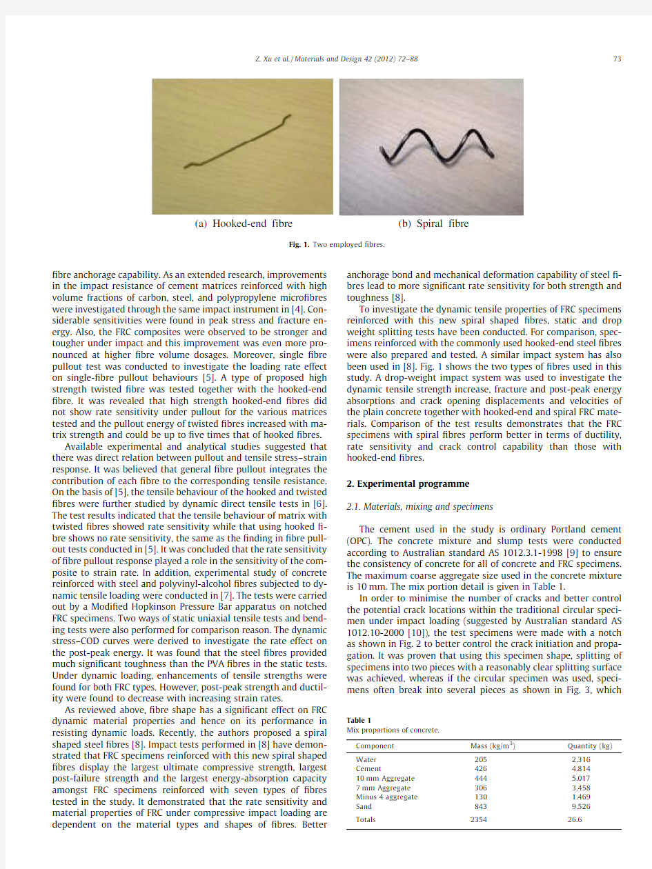
To investigate the dynamic tensile properties of FRC specimens reinforced with this new spiral shaped?bres,static and drop weight splitting tests have been conducted.For comparison,spec-imens reinforced with the commonly used hooked-end steel?bres were also prepared and tested.A similar impact system has also been used in[8].Fig.1shows the two types of?bres used in this study.A drop-weight impact system was used to investigate the dynamic tensile strength increase,fracture and post-peak energy absorptions and crack opening displacements and velocities of the plain concrete together with hooked-end and spiral FRC https://www.360docs.net/doc/e616652957.html,parison of the test results demonstrates that the FRC specimens with spiral?bres perform better in terms of ductility, rate sensitivity and crack control capability than those with hooked-end?bres.
2.Experimental programme
2.1.Materials,mixing and specimens
The cement used in the study is ordinary Portland cement (OPC).The concrete mixture and slump tests were conducted according to Australian standard AS1012.3.1-1998[9]to ensure the consistency of concrete for all of concrete and FRC specimens. The maximum coarse aggregate size used in the concrete mixture is10mm.The mix portion detail is given in Table1.
In order to minimise the number of cracks and better control the potential crack locations within the traditional circular speci-men under impact loading(suggested by Australian standard AS 1012.10-2000[10]),the test specimens were made with a notch as shown in Fig.2to better control the crack initiation and propa-gation.It was proven that using this specimen shape,splitting of specimens into two pieces with a reasonably clear splitting surface was achieved,whereas if the circular specimen was used,speci-mens often break into several pieces as shown in Fig.3,which
(a) Hooked-end fibre (b) Spiral fibre
Fig.1.Two employed?bres.
Table1
Mix proportions of concrete.
Component Mass(kg/m3)Quantity(kg)
Water205 2.316
Cement426 4.814
10mm Aggregate444 5.017
7mm Aggregate306 3.458
Minus4aggregate130 1.469
Sand8439.526
Totals235426.6 Z.Xu et al./Materials and Design42(2012)72–8873
makes the reliable extraction of the dynamic tensile properties of the tested specimens dif?cult.The dimension of the test specimen is100mm by100mm cylinder with an18mm triangular notch on This dimension was chosen in order to maintain dimension about three times as large as the?bre length.coarse aggregates,cement,and sand were?rst mixed before add-ing water.Mixing process continued for another3min before add-ing?bres.The?bres were manually dispersed and added to the mixer in order to avoid?bre clump.After being cured in the humid room for28days,the specimens were demolded and then both surfaces were properly levelled,sanded,polished,cleaned and dried to attain smooth surfaces before placing the strain gages.
The mechanical properties of the commonly used hooked-end steel?bre and the new spiral steel?bre suggested in[8]are listed in Table2.
2.2.Experimental test setup
In this study,45specimens were tested including six specimens for static compressive tests,eight specimens for static splitting tests and31specimens for dynamic splitting tests.
2.2.1.Quasi-static compressive and splitting tensile tests
Quasi-static compressive tests were conducted on a Baldwin Hydraulic Testing Machine in the UWA Structures lab with the standard procedures conforming with AS1012.9-1999[11].A Dig-iDaq logging system was used to record the load and displacement versus time.Strain gages were placed at the middle height of the specimen allowing the axial compressive strain histories of the specimens to be recorded[12].In this study,strain gages were placed at the two symmetric positions on each concrete cylinder surface and the strain histories were obtained by averaging the re-sults.The static compressive tests setup is shown in Fig.4a.
Quasi-static splitting tensile tests were also conducted on the Baldwin Hydraulic Testing Machine,as shown in Fig.4b.As shown, a high-strength steel adaptor was used between the platen and specimen notch to ensure that the loading was added properly to the notch and hereby the occurrence of vertical crack from the notch tip to the specimen bottom(Fig.4b).Two80mm strain gages were placed in parallel on the front surface of each tested specimen to measure the tensile strain history up to fracture,as shown in Fig.5a.Furthermore,a clip gage was placed horizontally across the left and right end of the tested specimen to measure the
Notched specimen:18mm triangular
Possible failure mode of circular specimen without notch under
?bres(Radmix).
Length(mm)Diameter(mm)
Fig.4.Quasi-static test setup on the Baldwin Hydraulic Testing Machine:(a)compression tests and(b)splitting tests.
Design42(2012)72–88
measure the https://www.360docs.net/doc/e616652957.html,yout of the two measuring devices is shown in https://www.360docs.net/doc/e616652957.html,parison of the results of the two methods will be dis-cussed in later sections.
2.2.2.Dynamic splitting tensile tests
2.2.2.1.Test layout.The layout of the instrumented drop-weight impact system used in this study is shown in Fig.7.The maximum drop height in this test rig is about 4m,which gives a theoretical drop velocity up to 8.85m/s.The impactor is made of a solid cylin-drical steel head,weighing 12.5kg.A plastic guide tube is used to ensure the impactor to be falling vertically to the target specimen.A number of circular holes were evenly made on the guide in order that the air could be squeezed out of the tube without dwindling the impactor velocity during the impact process.The test specimen was placed right beneath the guide tube with a load cell at the bot-tom of the specimen.The middle line of the impactor,guide tube,steel adapter,specimen and the load cell were aligned in a vertical line.
2.2.2.2.Data acquisition system and measuring devices.Two 80mm strain gages were placed on the front surface of each specimen to measure the strain history,which were in the same positions as those in the static tensile test setup shown in Fig.5a.The strain gages and load cells were connected to a high frequency data acquisition system composed of a fast-response A/D conversion card,a fast-response ampli?er and a graphical programming Lab-
view package.The same acquisition system was also used in the dynamic compressive tests in [8].
As described in the last section,the crack opening displacement was measured by the clip gage and the laser LVDTs in the static splitting test.However,neither of the two methods is directly applicable for the dynamic tests.The result of the clip gage under dynamic testing can be signi?cantly disturbed by the stress wave propagating from the notch tip,whereas the maximum sampling rate of the LVDT has a limitation of 700Hz (1.4ms per sampling point)which is not fast enough for the present impact test of which the loading process occurs within 1ms.The logging system devel-oped in this study has a maximum sampling rate of 2MHz for each channel,which is ideal to measure the deformation and impact loading of test specimens.However,since concrete is a brittle material,strain gages placed on concrete surface can only record strain histories before concrete tensile fracture occurs.In order to record concrete deformation after tensile splitting occurs,in the present study,a 10mm strain gage attached on a thin brass shim strip with a thickness of 0.02mm was made and used to measure the deformation after concrete cracking.This is termed as ‘brass gage’in this paper.Brass is an alloy of copper and zinc which has signi?cant ductility such that the strain gage on the brass can re-cord further deformation after concrete fracture under tensile loading.The crack opening displacement could then been derived by:
d ?
e ál
e1T
(a)Strain gages on the front surface (b) Brass gage on the back surface
Fig.5.Strain gage setup.
(a) LVDT (b) Clip gage
Clip gage
A
B
Fig.6.Two ways of measuring crack opening displacement in static splitting tests.
Z.Xu et al./Materials and Design 42(2012)72–8875
where d denotes crack opening displacement,e denotes the mea-sured strain value from brass gage and l denotes the length of strain grid.
As shown in Fig.5b,the brass strip was glued on the back sur-face at the middle height of the specimen with its middle section unglued so that the strain gage attached to the middle section of the brass strip can bridge across the predictable cracking area.It is of importance to point out that as exposing in the atmo-sphere,the brass shim has oxide ?lm layer covering on its surface which undoubtedly has a negative in?uence on the gluing quality between brass shim and concrete surface.The brass shim can be easily peeled off the specimen surface during the impact hence
the recorded brass strain is much lower than it ought to be.To min-imise this in?uence,in this study,each brass shim strip was metic-ulously and evenly deoxidized,including surface sanding,polishing and cleaning,in order to properly remove the oxide ?lm before being glued to the concrete surface so that the brass strip on each side of the brass gage can be closely clung to the left and right part of the test specimen,respectively.Deformation of the brass gage,which is mainly from the middle part across the concrete ‘cracking zone’,initiates when the concrete fracture occurs.Exam-ples of the measured strain results from the strain gages and the brass gage under the impact loading after deoxidizing are shown in Fig.9.It can be found that the stress wave propagates through
Crane
Guide tube
Trigger
Specimen and strain gage
Loadcell
High speed camera
Drop weight
SIGNAL FROM STRAIN GAGES AND LOAD CELL
Fig.7.Drop-weight High speed camera
1500w halogen
lights
Fig.8.Drop-weight splitting test setup.
76Z.Xu et al./Materials and Design 42(2012)72–88
Fig.10.A typical progressive failure process for plain concrete specimen under2m drop-weight impact at1000frame/s.
Table3
Quasi-static compressive test results.
Type of specimen Average
compressive
strength(MPa)Young’s
modulus
(GPa)
Strain gage Baldwin Hydraulic Testing Machine
Max.strain Toughness
(MJ/m3)
Fracture energy
(MJ/m3)
Post-peak energy
(MJ/m3)
Total toughness
(MJ/m3)
Plain concrete51.0930.70.00280.0973979080.0767458360.0032751280.0800210 Hooked-end FRC49.7633.40.0020830.0624012630.0522586670.0607428650.1130015
Spiral FRC53.334.10.00337170.137383280.0963030390.0687859660.165089005
Z.Xu et al./Materials and Design42(2012)72–8877
maximum strain at peak was measured by the strain gages placed on specimen surface.The average strain histories were also derived from the displacement measurement in the Baldwin Hydraulic Testing Machine.Accordingly,the fracture energy is obtained by both the strain gage results and the derived strain values,and is given in Table3.As can be noticed the fracture energies calculated by the two methods are comparable.
Comparison of the average compressive strengths and the max-imum strain for the three types of specimens is shown in Fig.11.As shown the spiral FRC has a higher strength than the hooked-end FRC and plain concrete.This observation is consistent with the tests results presented in[8].The maximum strain capacity of spir-al FRC is also found to be the largest in the three types of tested specimens,indicating that the spiral FRC has the largest fracture energy under compressive loading.
Fig.12shows the fracture energy,post-peak energy and total toughness of the three types of specimens.As shown,the plain concrete specimen has a total energy of0.08MJ/m3,a large propor-tion of which is fracture energy.Both the FRC specimens,however, have much higher post-peak energy and therefore higher total toughness,which indicates that FRC specimens have better energy absorption capacity than plain concrete specimen under compres-sive loading.It is also apparent in Fig.12that the spiral FRC has higher fracture energy,higher post-peak energy and hence higher total toughness than the hooked-end FRC and plain concrete under static compressive loading.Failure modes of the three types of specimens under static compressive loading are shown in Fig.13 where brittle shear failure occurs in plain concrete specimen, whereas?bres still bridge the cracks well after failure occurs in both of the FRC specimens,indicating better crack controllability and ductility.
3.1.2.Split tensile tests
3.1.2.1.Method of analysis.According to[14,15],the splitting ten-sile strength in a classic splitting test is calculated by:
T?
2P
p LDe2Twhere T is the splitting tensile strength,P is the maximum applied force indicated by the testing machine,L is the specimen length and D is the specimen cross-section diameter,and p LD/2can be consid-ered as an equivalent area for estimating the tensile strength of the specimen.
However,this equation cannot be applied to the present study because of the notch in the current test specimen,which leads to a smaller vertical force P.To determine the tensile strength of the current specimen,a modi?ed relation is derived in the present study as described below.In the present quasi-static splitting ten-sile tests,the splitting tensile strength can be derived by:
t?E ee3Twhere t is the splitting tensile strength,E is the Young’s modulus obtained from the static compressive tests,e is the maximum ten-sile strain measured by the strain gage.
By comparing the measured load and splitting tensile stress in static splitting tests,an‘equivalent area’A0can be derived based on P=tA0and used for splitting tensile strength estimation in both the static and dynamic splitting test.Table4shows the average equivalent areas for plain concrete,hooked-end FRC and spiral FRC specimen,respectively.As shown,the equivalent area some-what varies with various material types which can be due to the
C
R
F
l a r i p S
)c(
C
R
F
d n e
d e k o o
H
)b(
n i a l P
)a(
Fig.13.Failure modes under static compression tests.
78Z.Xu et al./Materials and Design42(2012)72–88
variety of the?bre’s bridging effect to the concrete matrix.Accord-ingly,the splitting strength can be calculated by:
r splitting ?aá
2P
p LDe4T
where r splitting is the splitting tensile strength,P is the maximum applied force indicated by the testing machine,L is the specimen length and D is the specimen cross-section diameter.Eq.(4)indi-cates that with the same tensile strength,the specimen without notch has a larger load capacity at failure than the current test spec-imen.The coef?cient a equals to2.13,2.5and2.67for the plain con-crete,hooked-end FRC and spiral FRC tested in this study, respectively.It should be noted that this is only an approximate relation of the splitting strength of specimens and the vertical force P based on equivalent tensile area.With the notch on the specimen, the splitting force the specimen can take is less than half of that without notch.However,the a coef?cients derived are only applica-ble to the specimen and testing conditions in this study.Changing such conditions,e.g.,use a different notch size,will change these
a coef?cients.
3.1.2.2.Failure modes under static splitting tests.The failure modes of the three types of specimens under static splitting tests are shown in Fig.14,where all specimens failed with one major crack in a direction almost parallel to the loading axis.It is also shown that the major crack split the plain concrete specimen all the way from top to bottom whereas the?bres still hold the two parts of FRC specimen together.Due to the spiral shape and therefore better bonding with concrete matrix,the spiral FRC displays larger elongation,higher residual strength together with higher energy absorption under static splitting tests.This observation will be fur-ther discussed in the next sections.
3.1.2.3.Stress–COD curves and stress–train relations.As mentioned above,two sets of sensors were used to measure the crack opening displacement,i.e.,LVDT and clip https://www.360docs.net/doc/e616652957.html,parisons of the mea-sured COD results are shown in Fig.15.As shown the results from the LVDT and the clip gage for all the specimen types are compara-ble although the result of the clip gage appears slightly larger than the LVDT.The difference was caused by the fact that the?xed LVDT are not always targeting at the same middle points of the specimen lateral surfaces during the loading and deformation process,as points A and B indicated in Fig.5.The targeting points would change when the two parts of specimen start to move apart and ro-tate around the bottom.
Fig.16shows the typical stress–strain relations up to fracture. The corresponding strain in the?gure was measured by the middle strain gage placed on specimen surface.The ultimate strain at frac-ture is summarised in Table5.It can be seen that the ultimate strains at fracture of the two FRC specimens are more than seven times larger than that of the plain concrete specimen,indicating larger deformation before fracture and therefore better ductility. The areas under the stress–strain relations of spiral and hooked-end FRC are very similar indicating similar energy absorption capacity before fracture(de?ned as fracture energy).Fig.17com-pares the typical stress–COD curves of hooked-end and spiral FRC.Since Fig.15a has shown that the plain concrete specimen has negligible COD as compared to the two types of FRC specimens, the stress–COD curve for plain concrete is not included in Fig.17. More clearly,the average residual strengths of two types of FRCs measured at COD of4mm and8mm are plotted in Fig.18.It is shown in the?gures that although the spiral FRC has a slightly lower tensile strength as compared to the hook-end FRC,it has higher ultimate displacement,higher residual strength at the same level of COD and larger area under the stress–strain curve,which implies higher post-peak energy capacity.
3.1.2.
4.Energy absorption capacity.Fig.19a shows the fracture energy,post-peak energy and the total toughness capacity of the three types of specimens,respectively.The post-peak energy is cal-culated by integrating the area under the stress–COD curve shown in Fig.17,whereas the fracture energy is obtained by the area un-der the stress–strain curves illustrated in Fig.16.In order to keep unit consistency,the strain histories in Fig.16are converted to specimen elongation by Eq.(1).
As shown in these?gures,although the hooked-end FRC has higher fracture energy capacity than the spiral FRC,the contribu-tion of fracture energy to the total toughness is trivial.It also dem-onstrates that the total toughness of spiral FRC is almost twice as high as the hooked-end FRC,indicating better ductility of spiral FRC under static splitting tests.This is because the spiral?bre has better bond than the hooked-end?bre at?bre-concrete interfaces.
In general,during?bre pullout process,adhesion and frictional bond are triggered in the?rst place which is followed by activation of the anchorage bond(mechanical component of bond caused by the deformation of the?bre such as the hooks in hooked-end?bre), as shown in Fig.20.Hooked-end?bres have relatively weaker adhesive and frictional bond due to its straight shape and weaker anchorage bond than the spiral?bres since their anchorage is only localised near the hooked-end areas.Moreover,both the frictional and anchorage bond of spiral?bres can be greatly enhanced by the fully deformed spiral shape comparing to the hooked-end?bres
Table4
Average equivalent area of the splitting tensile test.
Plain concrete Hooked-end FRC Spiral FRC
Equivalent area(mm2)7382.36142.015886.06
(a)Plain(b)Hooked end FRC(c)Spiral FRC
Fig.14.Failure modes under static splitting tests.
Z.Xu et al./Materials and Design42(2012)72–8879
(Fig.20).In particular,the frictional bond on the spiral?bre can be potentially strengthened by the radial?bre–matrix extrusion dur-ing?bre pullout.Based on the spiral?bres’three-dimensional characteristics,the spiral?bre also has a torsional resistance dur-ing untwisting procedure.All of the above potentially lead to sig-ni?cant energy dissipation during?bre pullout process.Similar discussions regarding the bond-slip mechanisms of the hooked-end,fully deformed and smooth?bres under static pull-out tests were also made in[16]where the hooked-end and deformed?bre (undulated?bre)were found to have higher resistance and the pull-out energy than the smooth?bres due to the mechanical con-tributions(end hooks and surface deformations,respectively).The study did not compare the hooked-end?bre with the deformed ?bre.
3.2.Dynamic split tensile test results
3.2.1.Time lag effect
In this study,the impact split tensile tests were conducted with two drop heights:2m and3.8m.The impact force was measured
80Z.Xu et al./Materials and Design42(2012)72–88
by a fast response load cell placed under the test specimen and the fracture strain and the COD at the middle height of specimens were measured and derived by the strain gages and the brass gages.As shown in Fig.9,there are time lags between the top strain,middle strain,and load histories,indicating stress wave propagation dur-ing the impact process.The time lag between the top and middle strain is trivial since the two strain gages were placed very close to each other.
In Fig.9a,it can be seen that both the top and middle strain gage readings reach their maximum values of about 7000microstrain and then rocket up to the truncated level immediately,indicating the strain gage has fractured and failed together with concrete.On the other hand,the brass strain reading which bridged across the ‘potential cracking zone’initiates when fracture happens and
Table 5
Quasi-static split tensile test results.Type of specimen Average tensile strength (MPa)Ultimate strain at fracture Residual strength (MPa)Fracture energy (MJ/m 3)
Post-peak energy (MJ/m 3)Total toughness (MJ/m 3)
Plain concrete 4.4579927670.0005830
0.0022800510
0.002280051Hooked-end FRC 6.8716997990.004020.5193199380.022*******.224070990.246515652Spiral FRC
6.306781069
0.00384
1.99381762
0.019840019
0.472220478
0.492060498
e
r b i f l a r i p S )b (e r b i f d n e -d e k o o H )a (Anchorage bond
Adhesive and frictional bond
Matrix
Adhesive and frictional bond
Anchorage bond Matrix
Fig.20.Anchorage bond bond between ?bres and matrix.
Z.Xu et al./Materials and Design 42(2012)72–88
81
ascends all the way to about17,000microstrain and then to the truncated level,this result demonstrates the ductility of the brass material and the effectiveness of the brass gage for measuring the post-peak deformation.
Fig.21shows the relationship between strain rates and the cor-responding measurable maximum strain capacities from both mid-dle strain gages and brass gages.The maximum strain rates of specimens are obtained from the recorded strain histories,which are de?ned as the strain rate value in this study.The same de?ni-tion was also used in[8].It is shown in the?gure that in spite of some variability in test results,the measurable maximum brass strains are about three times larger than those recorded by the middle strain gages,indicating that as a more ductile material,brass gage is able to capture more deformation than the strain gage under the same impact loadings.As shown strains measured by both the normal and brass strain gages illustrate obvious rate sen-sitivity under impact loading.The rate effects on the fracture strain capacities from the both measurements are,as expected,very similar.
https://www.360docs.net/doc/e616652957.html,parison of impact loadings
The split tensile stress histories up to8000l s for different spec-imen types measured in this study are presented in Fig.22.As shown,under the2m and3.8m drop weight impact,the tensile stresses of plain concrete specimens vary from4.5MPa to9MPa with the complete failure occurred at about600l s.Brittle tensile failure due to splitting of the specimen along its centreline was ob-served under the both drop heights as shown in Fig.23a.The hooked-end FRC shows a tensile stress level up to22MPa.The dy-namic stresses?uctuate with time after reaching the peak value, which is accompanied by?bre pullout.These processes would con-tinue until about2600l s when the specimen was completely damaged after all?bres had been pulled out and residual stress values dropped to zero.The corresponding failure modes of hooked-end FRC are shown in Fig.23b.
As to the spiral FRC specimens,the strength level is close to the hooked-end FRC,ranging from12to22MPa.However,the stress histories displayed signi?cant multi-peaks and therefore substan-tial residual strengths after the?rst peak.This is because of the better frictional and anchorage bond between spiral?bres and the concrete matrix.For hooked-end?bres,only the anchorage bond mainly contributes to the tensile resistance[3,5].After anchorage bond is overcome(Fig.20a),i.e.,the hooked ends are straightened or partly straightened,the frictional bond would also
82Z.Xu et al./Materials and Design42(2012)72–88
be overcome before ?bres are fully pulled out,which,nevertheless,has been found only accounts for a minority proportion of the total bond for hooked-end steel ?bres [3].On the other hand,the ?bre pullout process for spiral ?bres is signi?cantly more complex.The spiral ?bre is fully curved along its length in concrete matrix such that the anchorage bond,which acts radially on the ?bre body (Fig.20b),would accompany the ?bre pullout process all the way until the ?bre end is fully pulled out of the matrix.The frictional bond acting tangentially is also signi?cantly enhanced because of the radial bond force from the concrete matrix (Fig.20b).During the pull-out process,the mechanical deformation along the spiral ?bres displaces the ‘concrete tunnel’encasing them.When the concrete is crushed,the splitting load decreases.However,the loads rise up again when the deformation enters other ‘concrete tunnels’.This can be further observed in the stress histories of spir-al FRC in which the ?bre pullout processes lasted for longer than the hooked-end ?bres,indicating that more energy is needed to fully pull out the spiral ?bres.Typical failure modes for spiral FRC under impact tests are shown in Fig.23 c.
2m
4m
(a)Plain concrete
(b)Hooked-end FRC
(c)Spiral FRC
Fig.23.Failure modes under drop weight impact tests.
0.5
1.5
2.5
3.5
4.5
5.5
6.5D I F
Concrete Hooked-end FRC
Spiral FRC
0.5
1.5
2.5
3.5
4.5
5.5
0.0001
0.011
100
10000
0.0001
0.01110010000
D I F
Maximum strain rate Average strain rate
(a)
(b)
Z.Xu et al./Materials and Design 42(2012)72–8883
3.2.3.Rate effect on dynamic tensile strength and strain capacity
The effect of strain rate on the dynamic tensile strength is illus-trated in Fig.24a.The dynamic increase factors(DIF)are obtained by normalising the dynamic tensile strengths by the corresponding static tensile strength.As shown,the three types of specimens are all rate sensitive with respect to the dynamic tensile strength.It also shows that the dynamic increase factors for both the FRC materials are larger than that for plain concrete material,indicat-ing that FRC materials with?bre dosage of1%tested in this study are more rate sensitive than the concrete material without?bres. As also shown in the?gure the DIF for spiral FRC increases faster than the hooked-end FRC and plain concrete material,indicating the?bre shapes have an effect on rate sensitivity.However,it should be noted that the difference in rate sensitivities between the hooked-end FRC and spiral FRC are not as prominent as that be-tween the hooked-end FRC and plain concrete,implying the?bre content is more critical in the tensile strength DIF than the?bre shapes.It should be pointed out that the de?nition of strain rate plays an essential role in the concrete tensile DIF values.The inher-ent time-variable attribute of strain rate for concrete brings dif?-culty and controversy when investigating materials’dynamic properties.In this study,the strain rate is assumed as the maxi-mum strain rate which results in a smaller DIF than some of the experimental results summarised in[17]where the strain rates were conservatively de?ned as the average value.A comparison of the in?uence of strain rate assumption on the DIF is shown in Fig.24b,in which it is shown that by using the average strain rate the DIFs are signi?cantly larger than DIFs calculated by the maxi-mum strain rate values.
Plots of the fracture strain capacities versus strain rate of the three tested materials are compared in Fig.25,in which it is obvi-ous that the maximum measurable strain capacities are also rate sensitive.This observation is consistent with the experimental re-sults in[18].Similar to the trend curves in Fig.24,spiral FRC dis-plays the most signi?cant rate effect on the fracture strain capacity among the three types of specimens.This observation im-plies that the spiral?bres have a better capability of controlling microcracks than the hooked-end?bres so that under the same drop weight impact,i.e.,the same energy input,the spiral FRC de-forms in a more uniform and ductile way than the hooked-end FRC and plain concrete specimen before fracture.
3.2.
https://www.360docs.net/doc/e616652957.html,parison of stress–strain relations,stress–COD relations and rate effect on energy absorption
Some typical stress–strain and stress–COD relations of the investigated three material types are illustrated in Figs.26and 27,respectively,in which the stress histories are derived by Eq.
(4),while the strain histories are obtained through the middle strain gages placed on specimen surfaces.The stress–strain curves are plotted up to the measurable fracture strains from strain gages whereas stress–COD curves are plotted up to the fracture strains from the brass gages,as indicated in Fig.9b.As stated in Section 2.2.2,the crack opening displacement is obtained by Eq.(1).The rate effect on the corresponding fracture energy,post-peak energy and total energy for all the tested specimens are listed in Table6 and plotted in Fig.28.
In general,as clearly shown in Figs.26–28,both FRC specimen types achieve higher fracture energy,post-peak energy and total toughness than the plain concrete material,indicating the FRC materials investigated in this study have better energy absorption capacities than plain concrete under impact loading.Furthermore, it is apparent that the two types of FRC specimens have very sim-ilar level of fracture energy capacity and the corresponding rate sensitivity.The primary difference of the two FRC types is
their 84Z.Xu et al./Materials and Design42(2012)72–88
post-peak energy capacity and therefore the total toughness.As shown in Fig.27,in spite of some variabilities in impact test re-sults,the spiral FRC specimens generally show split-hardening behaviours whereas their counterparts with hooked-end?bres mainly display split-softening behaviours,indicating the higher post-peak ductility of spiral FRC.This is also shown in Fig.28b and c in which both the energy absorption and rate sensitivity of spiral FRC are more signi?cant than the hooked-end FRC material.
The different performances of the two types of FRC specimens are due to the different?bre shapes.As discussed above,the spiral FRC has better frictional bonding and anchorage bonding(Fig.20) so that it has higher energy absorption capacity under splitting tensile tests.On the basis of these reasoning,it is not dif?cult to ex-plain the above observations.For FRC specimens with the two?bre types,the anchorage bond plays an important role in the rate sen-sitivity of energy absorption capacity during the?bre pullout at high loading rate,as also found in[3,5,8].The hooked-end?bre FRC displays less rate sensitivity when pulled out from concrete matrix primarily because the anchorage bond only localised in vicinity of the hooks,whereas the spiral?bre provides a3D anchorage bond distributed along the entire embedded?bre length.Similar results have also been reached in[5]where the high-strength hooked?bres showed no appreciable rate sensitivity in high rate pullout tests.
Pullout tests from other researchers have also revealed that straight?bres shows no appreciable rate sensitivity([2]),indicat-ing the frictional component of bond is not rate sensitive for straight?bres.On the other hand,the frictional bond from the spir-al?bres takes much larger proportions of the total bond because it is increased by the extrusion between the matrix and?bres during the?bre pullout.Since concrete is a rate sensitive material,the?c-tional component of bond for spiral FRC can also be rate sensitive. Moreover,the untwisted moment resistance of the spiral?bre is also rate sensitive since they are fabricated by high strength steel, which itself is a rate sensitive material.Therefore,the spiral?bre has a greater in?uence on the rate sensitivity of energy absorption.
3.3.Image analysis
With the high speed video camera,the crack opening process of specimens can be recorded in detail.In this study,the drop weight split tensile tests were recorded at10,000frames/s.The crack opening processes of plain concrete and the two types of FRC spec-imens are investigated by analysing the images through a Matlab programme using image processing toolbox.The average strain rate estimated by image analysis is comparable to the strain rates obtained from the middle strain gages,as shown in Fig.29.The similar approach for deformation analysis was also employed in [8].This observation demonstrates that image analysis is applica-ble to accurately estimate the maximum strain rate of specimens in dynamic splitting tests,which brings convenience to future study.
Typical plots of crack opening displacements up to2500l s of the tested specimen under2m drop weight impact are shown
in Z.Xu et al./Materials and Design42(2012)72–8885
Table6
Dynamic split test results.
Specimen designation Fracture
strain
Max.brass
strain
Maximum strain
rate(1/s)
Dynamic tensile
strength(MPa)
DIF Fracture energy
(MJ/m3)
Post-peak energy
(MJ/m3)
Total energy
(MJ/m3)
Plain1a5831.6956017112.3412.34 2.80.02980.020.0498 Plain2a3552.21613541.22586.414989.55 2.10.005240.0470.05224 Plain3a6455.310,53237.3928.18 1.80.0140.020.034 Plain5a6097.516,599137.2318.72 4.20.04380.0780.1218 Plain33a5737–a101.2214.52 3.30.0462––Plain7b6593.811176.7114.916.71 3.70.0410.0240.065 Plain8b4968.516335.7106.08413.12 2.90.02640.0770.1034 Plain9b403213848.697.81614.62 3.30.010.0730.083 Plain91b367611,82684.1515.19 3.40.010.0690.079 Plain4a5610642157.1214.92 3.30.01950.0320.0515 Hooked-end1a530710,85398–––––Hooked-end12a44874877.7679.218.97 2.80.020.0450.065 Hooked-end11a5206.617874.59817.92 2.60.080.130.21 Hooked-end2a5211.96596267.528.65 4.20.1350.0590.194 Hooked-end3a5670.8718200.38874.88225.77 3.80.0770.07740.1544 Hooked-end52a407896377023.63 3.40.0710.07320.1442 Hooked-end51a5264670657.315.16 2.20.0730.0670.14 Hooked-end7b32058394.712832.28 4.70.1410.1230.264 Hooked-end8b202218,70960.3724.13 3.50.010.0950.105 Hooked-end11b881217,040107.33439.94 5.80.1170.190.307 Spiral13a6109.310,80278.3221.58 3.40.0940.280.374 Spiral10a9669848289.924.17 3.80.1230.180.303 Spiral11a4486.311917.69776.822.14 3.50.040.0980.138 Spiral3a660716,00067.45516.26 2.60.0480.150.198 Spiral5a4143.46581.377.916.61 2.60.02060.070.0906 Spiral6a822118,06885.27325.95 4.10.07440.190.2644 Spiral4a5315889772.628.19 4.50.050.0250.075 Spiral7b506917,56975.84327.07 4.30.140.270.41 Spiral8b787615,985112.9828.68 4.60.080.1740.254 Spiral4b462310,56677.630.88 4.90.05380.160.2138 Spiral9b4504.7937010033.36 2.80.1120.170.282
a Missed data.
86Z.Xu et al./Materials and Design42(2012)72–88
Fig.30.As shown,both the FRC specimens display slower crack opening rate than the plain concrete,and the spiral FRC has the slowest crack opening rate,indicating the spiral ?bres provided better control over the crack growth than the hooked-end ?bres.The corresponding crack opening velocity,which is taken as the average slope of the crack opening displacement time history is shown in Fig.31.As shown,the crack opening velocity of the spiral FRC specimen is the smallest,while that of the plain concrete is the
fastest.It also shows that,as expected,the crack growth rates are higher under higher drop height because of the higher loading rate.The difference of the crack opening rates between the hooked-end FRC and spiral FRC specimens decreases when the drop height in-creases,which implies the ?bre dosage could have more signi?cant in?uence on the crack opening than the ?bre shape at high loading rates.
4.Conclusion
As an extension of a study presented in [8],this study con-ducted both quasi-static and dynamic splitting tests to investigate dynamic tensile properties of FRC materials.The FRC specimens with the newly proposed spiral shaped ?bres and the conventional hooked-end ?bres,as well as specimens made of plain concrete material were tested.Due to the well-known uncontrollability of impact tests,notch shaped specimens were made in this study to better control the splitting surface of the specimens in drop-weight tests.
According to the test results,FRC specimens with the two ?bre types showed better performance than plain concrete material un-der both static and dynamic splitting tests in terms of tensile strength,fracture energy,post-peak energy,DIF,maximum mea-surable strain capacity,rate sensitivity and crack growing velocity.Although the FRC specimen with hooked-end ?bres,to some ex-tend,showed higher tensile strength and fracture energy under both static and dynamic conditions,it had lower measurable strain capacity,total toughness,crack controllability and therefore lower ductility under the tested strain rate range than the FRC specimens with spiral ?bres.This is because its weak adhesive and frictional bond and limited anchorage bond merely localises near the hooks.The spiral FRC also showed higher rate sensitivity to both strength and energy absorption because of the rate sensitivity of its fric-tional bond,anchorage bond,untwist resistance along with the inherent rate sensitive characteristic of concrete and steel material.As presented in [8]and the present study,the spiral ?bre FRC has comparable compressive strength and tensile strength under both static and dynamic loading as hooked-end FRC.However,it outper-forms the hooked-end FRC in terms of ductility,toughness,crack controllability and more signi?cant rate sensitivity because of its better bond between concrete matrixes owing to its three-dimen-sional twisted ?bres shape.
The test results demonstrated the effectiveness of the dynamic load resistance capacity of the spiral ?bre FRC.Acknowledgements
The authors would like to thank Australian Research Council for the ?nancial support under Grant No.DP1096439,and China Na-tional Nature Science Foundation under Grant No.51078094for conducting the research work.
References
[1]Suaris W,Shah SP.Strain-rate effects in ?ber-reinforced concrete subjected to
impact and impulsive https://www.360docs.net/doc/e616652957.html,posites 1982;13:153–9.
[2]Gokoz UN,Naaman AE.Effect of strain-rate on the pull-out behaviour of ?bres
in mortar.Int J Cem Compos Lightweight Concr 1981;3:187–202.
[3]Banthia N,Trottier J-F.Deformed steel ?ber-cementitious matrix bond under
impact.Cem Concr Res 1991;21:158–68.
[4]Banthia N,Chokri K,Ohama Y,Mindess S.Fiber-reinforced cement based
composites under tensile impact.Adv Cem Based Mater 1994;1:131–41.
[5]Kim DJ,EI-Tawil S,Naaman AE.Loading rate effect on pullout behavior of
deformed steel ?bres.ACI Mater J 2008.
[6]Kim DJ,El-Tawil S,Naaman A.Rate-dependent tensile behavior of high
performance ?ber reinforced cementitious composites.Mater Struct 2009;42:399–414.
[7]Cadoni E,Meda A,Plizzari G.Tensile behaviour of FRC under high strain-rate.
Mater Struct
2009;42:1283–94.
Z.Xu et al./Materials and Design 42(2012)72–8887
[8]Xu Z,Hao H,Li HN.Experimental study of dynamic compressive properties of
?bre reinforced concrete material with different?bres.Mater Des 2012;33:42–55.
[9]AS101231-1998.Methods of testing concrete–determination of properties
related to the consistency of concrete–slump test.Sydney:Australian Standard.
[10]AS101210-2000.Methods of testing concrete–determination of indirect
tensile strength of concrete cylinders(Brasil or splitting test).Sydney: Australian Standard.
[11]Swamy RN,Jojagha AH.Impact resistance of steel?bre reinforced lightweight
concrete.Int J Cem Compos Lightweight Concr1982;4:209–20.
[12]Bischoff PH,Perry https://www.360docs.net/doc/e616652957.html,pressive behaviour of concrete at high strain rates.
Mater Constr1991;24:425–50.[13]Zhai Y,Ma G,Zhao J,Hu https://www.360docs.net/doc/e616652957.html,parison of dynamic capabilities of granite and
concrete under uniaxial impact compressive loading.Yanshilixue Yu Gongcheng Xuebao/Chin J Rock Mech Eng2007;26:762–8.
[14]Timoshenko S,Goodier J.Theory of elasticity.3rd ed.London:McGraw-Hill
Book Company;1970.
[15]Wang ZL,Liu YS,Shen RF.Stress–strain relationship of steel?ber-reinforced
concrete under dynamic compression.Constr Build Mater2008;22:811–9. [16]Naaman AE,Najm H.Bond-slip mechanisms of steel?bers in concrete.ACI
Mater J1991;88:135–45.
[17]Malvar LJ,Ross CA.Review of stain rate effects for concrete in tension.ACI
Mater J1998;95:735–9.
[18]K?rmeling HA,Reinhardt HW.Strain rate effects on steel?bre concrete in
uniaxial tension.Int J Cem Compos Lightweight Concr1987;9:197–204.
88Z.Xu et al./Materials and Design42(2012)72–88
前台新进员工带教手册(V11)
前台新进员工带教手册 目录 一、海友酒店介绍 1.1品牌故事 1.2产品特征 1.3目标客户群 二、海友酒店前台交接班制度 2.1 交接班准备 2.2 交接事项 2.3 填写交接班本 2.4 接班事项 2.5 交接班签名 三、海友酒店前台员工带教计划 3.1 带教目的 3.2 带教内容 一、海友酒店介绍: 1.1品牌故事 海友酒店是华住酒店集团(原汉庭酒店集团)旗下的风格经济型酒店连锁品牌,致力于为有预算要求 的客人提供“欢乐、超值”的住宿产品。 我们全情投入,与顾客真诚沟通,分享快乐,为客人提供愉快、舒适的住宿体验。一切从我们的“HI”开始。。。。。。 2005年初,华住在中国正式创立,同年8月,第1家门店开业,2006年底,旗下的汉庭酒店第34 家开业。2007年7月,华住以股权融资8500万美元创下中国服务行业首轮融资的新纪录,2007年底,汉庭酒店第74家开业。2008年初,汉庭在全国签约门店数达到180家,完成了全国主要城市的布局,并重 点在长三角、环渤海湾、珠三角和中西部发达城市形成了密布的酒店网络,成为国内成长最快的连锁酒店品牌之一。2008年4月,汉庭已开业酒店超过100家,出租率、经营业绩各项指标均在业内处于领先地位。 2008年2月,华住酒店集团正式成立,是国内第一家多品牌的酒店集团。华住致力于实现“中国服务”的理想,即打造世界级的中国服务品牌。华住的愿景是“成为世界住宿业领先品牌集团”,为此,我们将不断追求精细化的管理,实施标准化的体系和流程,更全面、更迅速地推进集团化发展。华住酒店集团旗下目前拥有禧玥酒店、星程酒店、汉庭酒店、全季酒店、海友酒店五个系列品牌,我们将坚持时尚现代、便捷舒适、高性价比的优势特点,塑造中国酒店的典范。
中华淘金网商业计划书--商业计划书
中华淘金网商业计划书--商业计划书 第一部分网页提案 目录 1、策略综述 2、意念的引入 3、站点基本描述 4、功能的实现以及费用的预算 5、项目进度安排 6、维护与升级 7、未来扩展项目 8、附录 1、意念的引入 在当前的网络社会中,由于技术上的原因,当前网民在网络中的自由受到诸多的限制。我们不妨将当前的网络世界比做人类社会发展史上的原始社会,当中的网民犹如原始社会中的原始人,在他们力所能及的网络空间内进行一系列的采集-狩猎活动。面对这些原始人,我们只能以非常简单的思维模式去考虑他们在网络空间的行为。 如何吸引他们到我们的网站进行采集--狩猎活动? 人类的需要是多元化的。按马斯洛对人类需要的分层,结合当前网络社会的特点分析上网的人,他们在现实世界已解决了最基本生理需要,包括避免饥饿,逃避危险等,在网上虚拟的空间他们所追求,将是较高层次的多元化需求,如获得爱与尊重,实现自我价值。 如何才能满足网民高层次多元化需求的满足呢? 一方面是简单的思维与行为模式,一方面是高层次多元化需求的满足。如何把这两方面有效的结合起来将是我们的网站成功的关键。 2、策略综述 利而诱之是我们的第一个策略。 综观当前的各类网站,主要为网民提供了各种各样的服务,包括提供各类的新闻、图片资讯;让网民注册,申请电子邮箱,免费主页空间,进行聊天;有的甚至提供物品的拍卖,网上购物服务,归根结底,他们就是要吸引网民的注意力,让他们在网站进行采集--狩猎活动。我们也将采取这一策略,但侧重于网络派钱的概念。 强调商业操作是我们的第二个策略
考察各种大众媒体工具(mass media)的发展史,我们可以看到每一种大众媒体工具(如广播,报纸,电视广播)的背后都有一套完善的商业操作,以及有效的资金来源支撑着。网络营运也必须找到它的资金来源。 在当今网络原始时代,众人都希望在网络营运中找到那只会下金蛋的母鸡。我们也不例外,一系列的商业操作(那只会下金蛋的母鸡)将是我们网站生存的关键。 倡导创意将是我们的第三个策略。 人是一种狡猾的动物,在原始本能驱动下所产生的动机,往往要堂而皇之地掩饰一番。为扩大我们网站的受众,提高我们网站的品位,倡导创意将是必不可少的。创意正是根源人类具有不安守本份的本能冲动。满足了人类这一本能冲动的网站将是成功的。 倡导多元化是我们的第四个策略 世界在网络的联结下变得越来越小,网络空间所聚集的人来自不同的国家地区,有着不同的需求。我们并不幻想以单一的网站满足网民的所有需要,但我们会以一系列网群的策划来实现多元化。 3、站点基本描述 A、站点结构概念 多面体两层结构:固定的STATION WEB SITE与流动的TOPIC WEB SITE,最大限度地网罗资讯与网民。我们所重视不是单一网站的概念,我们的视线亦将不再是局限于单一网站的建设,我们倡导网站群的概念,从整体上来规划一系列的网站。 我们这些单独网站之间的有机连接将形成一个以中华淘金网为首的网站群。 我们的网站群分为两类: 一类是两个固定的STATION WEB SITE,特点是长期存在,规模大,交互功能强,是进行BtoC、BtoB的服务界面。我们将设置一个主要的网站:面对网民和面对企业的的淘金网。 一类是一系列流动的TOPIC WEB SITE。特点是主题鲜明,内容简洁,规模小,极具娱乐性、艺术性与时效性,存在时间根据其主题以及赞助商来定,一般不超过一年。 固定的网站在一系列小型流动的网站包围下,互相进行功能的互补,分工是十分明确的。我们的设想是以淘金网为主导,通过淘金网进行一系列的市场营销活动以及市场调研活动,另一方面,淘金网又以有偿定向投稿的方式为一系列的流动主题网站提供源源不断的资讯更新。而流动主题网站则通过鲜明的主体吸引广大的网民进行浏览,以及引导网民进入我们的淘金网,负起扩大淘金网与外界联系的功能。
基于因子分析法的我国2012年各类型商业银行的经营业绩及排名
理学院课程项目 课程名称: 数据分析 题 目: 基于因子分析法的我国2012年各类型 商业银行的经营业绩及排名 班 级: 信科112 姓名学号: 冯力 11480010242 指导教师: 梁方楚 2014年5月30日
目录 摘要 (1) 1 问题的提出 (1) 2 研究背景 (1) 3 因子分析法的数学模型 (2) 3.1因子分析法的概念 (2) 3.2因子分析的计算步骤 (2) 4 样本的选择和指标体系的建立 (4) 4.1 样本的选择 (4) 4.2 我国上市银行经营绩效评价的指标选取 (4) 5 各类银行因子分析及其结果 (5) 5.1 数据查找 (5) 5.2数据处理 (5) 6 结论 (10) 7 参考文献 (11) 8 课程小结体会 (12) 附录 (13)
摘要 报告选取了中国银行,工商银行,建设银行,交通银行,中国农业银行,中信银行,中国民生银行,招商银行,中国兴业银行等16家具有代表性的国内上市商业银行作为此次研究的样本,这16家商业银行中包括5家国有控股商业银行,11家大中小型股份制商业银行,然后通过借鉴我国现行的商业银行业绩评价体系,最终确定了总资产收益率、人均利润、成本收入比、营业收入利润率、资本充足率、不良贷款率、拨备覆盖率、流动比率、存贷比率、存款增长率和非利息收入增长率为评价的11个指标,从各个方面对商业银行的经营业绩进行评价。 关键词:商业银行评价指标经营业绩因子分析
1 问题的提出 商业银行是经营货币资金、授受信用的特殊企业,是现代金融体系的重要组成部分。高效健全的银行体系能够为社会提供方便快捷的服务,安全稳健的银行经营对国民经济发展具有重要意义,同时经营绩效的高低不但会关系到银行本身能否良好运作,而且对整个国家宏观经济运行有着重大影响。 2 研究背景 随着我国银行业的全面开放,国内银行将面临更大的挑战和考验,在日益激烈的竞争环境中,商业银行提高经营绩效,增强竞争力势在必行。在这种背景下,按照现代商业银行经营绩效管理的要求,对我国的商业银行进行科学全面的评价,发现现阶段商业银行经营管理中存在的不足并提出应对方法,从而提高商业银行经营的绩效,就不仅是商业银行自身发展的客观需要,更是商业银行应对国际挑战和竞争的现实需要。
新员工带教流程
新员工带教流程 第一天: 熟悉公司的作息时间,了解公司基本状况,基本服务礼仪与动作规范,学习做迎宾。 1、上班时间:10:00---19:30 12:00----21:00 (转正前) 10:00--16:00 14:30---21:00(转正后) 备注:时间根据季节调整。 2、管理手册:P1、江明商贸简介(了解即可,店长须以解说的方式进行); 3、服务礼仪:1)仪容仪表标准; 2)服务动作规范(站姿、蹲姿、距离、手势、角度); 3)学习做迎宾(声音、表情、语调、迎宾位置); 4)电话礼仪; 第二天: 了解公司的考勤制度,产品的风格分类及陈列 1、相关制度的了解:《考勤制度及请假报批程序》《离职程序》; 2、产品风格分类(①以鞋来区分:男鞋、女鞋、童鞋②以季节来区分:春秋单鞋、夏季凉鞋、冬靴③以鞋头区分:尖头、圆头、方头④以鞋跟来区分:平跟3CM以下、中跟3.1CM--5CM、高跟5.1CM---8CM、特高跟8.1CM 以上⑤以鞋帮来区分:凉(拖)鞋、中空鞋、浅口鞋、满帮(低腰)鞋、短靴(筒高14CM以下)、中靴(筒高15--22CM)、长靴(筒高23--36CM);(以店铺现有货品实物讲解方式进行带教) 3、了解什么是陈列,为什么做陈列、陈列标准及陈列原则。 第三天: 掌握《会员卡》的办理及使用规范,相关票据的填写及操作流程,鞋类产品从哪六个方面进行描述。 1、“会员卡”的申办标准及使用细则; 2、相关票据:《销售单、销售退货单》《调拨单》《会员单》正确填写; 3、鞋类产品从:楦型、皮料、底材、高度、风格、线条六方面描述(以实物操作讲解带教为标准); 4、服务1--2步:细节重点的掌握及实操应用。 第四天: 了解鞋类基本皮料、材质的特性及打理保养方法,所属品牌货号含义,FABE\法则应用,服务三、 四步,轮流做迎宾。 1、皮料特征及打理方法、皮料的分类(牛、羊、猪、打蜡、漆皮、磨砂皮);(以店铺现有货品实物讲解方式进行带教) 2、了解所属品牌货号的含义; 3、服务技巧之FABE、含义理解及应用; 4、服务三、四步的细节重点的掌握及实操应用。 第五天: 学习掌握公司销售技巧及服务规范流程和语言表达标准、掌握做报表及相关单据技能,初步了解库存及货品摆放位置,服务五、六步、协助做销售。 1、销售技巧:USP/AIDA的含义及实操应用(以场景模拟带教实操为主) AIDA A:注意(Attention) 1)商品陈列 2)导购员的仪容、仪表 3)精神奕奕热忱的招呼(三声) 4)卖场气氛 I:兴趣(Interest) 1)接近顾客了解顾客购物动机 2)让顾客触摸商品 3)有效介绍货品的特性及卖点 4)为顾客做参谋 5)邀请试穿 D:欲望(Desire) 1)介绍FAB及USB 2)强调物超所值不可代替 3)化解顾客疑虑及异议 A:行动(Action) 1)把握时机完成交易 2)介绍打理知识 3)介绍其他配成产品 4)付款过程快速 USP(Unique selling piont)独特销售点: 质料、设计款式、手工、处理方法、色彩、价钱 2、开放式与封闭式的语言技巧:产品推荐:O O C 促成销售: C O C 3、初步了解库存及货品的摆放位置、辅助老员工做销售 4、掌握报表的正确填写、各项单据的电脑操作
0027~0030-旅游投资的商业模式研究――3L坐标分析法
旅游投资的商业模式研究――3L坐标分析法 2005年12月5日第3506期2005年12月12日第3509期 2005年12月19日第3512期2005年12月26日第3515期 杨光林峰 一、3L坐标分析法 民间投资商,已经成为旅游产业发展的主力军。这些旅游投资人,对于如何锁定风景及土地资源、如何确定项目的主题与市场定位、如何建设出具有吸引力的产品、如何实施有效的营销,最为重要的是如何获取盈利,都在反复思考,并感到不易把握。 投资商最关心的,就是如何获取利润。 旅游产业的综合行太强,投入大而获利周期长,因此盈利方式很难用简单的算数进行计算。对盈利方式中的盈利时序、盈利大小、盈利结构没有搞明白时,投资的决心是很难下定的。如果此时投资进入运作,往往会形成“摸着石头过河”的局面,走一步看一步。结果一般都是:效率低下,大走弯路。 旅游开发所涉的层面很多,开发运作环节复杂,交叉联动行业多。明晰的商业模式可以让投资者透过错综复杂的表象,看清具体项目的关键问题所在,项目的风险和利润所在,在具体的运作中能够从容以对。 因此,借助专业机构的经验与技术,进行旅游项目开发的商业模式设计,是投资商借脑中最重要的一个环节。 旅游商业模式设计――全面综合的研究旅游项目开发,系统解决锁定资源、定位主题与市场、设计并成型产品、制定营销战略,清晰建构盈利模式。 设计合理的商业模式需要实用有效的技术工具,通过该工具可以将投资过程中可能涉及到的各个层面和问题加以考虑,找出最适合项目的解决方案。 我们为此长期研究旅游产业经济及具体投资项目,并逐步建立了一套旅游投资商业模式专用分析工具――3L坐标分析法(或三链坐标分析法)。 通过持续的具体项目实践和理论研究,我们发现,由三个角度出发的链条(旅游业价值链、旅游开发运作链、旅游产业联动链)构成的坐标系(如下图所示)。在旅游产业中所有可能的商业模式,都能在该坐标系中找到位置;而任何旅游产业的项目,都可以运用3L坐标进行分析,从而发现盈利点、盈利结构,并由此形成商业模式的构架;对于旅游企业或正在经营中的旅游景区,运用3L坐标进行分析,可以对企业或景区进行诊断,发现其原有商业模式的缺陷,找到新的盈利增长点,寻找出可持续扩展的盈利新模式。
前台新进员工带教手册
一、海友酒店介绍 1.1 品牌故事 1.2 产品特征 1.3目标客户群 二、海友酒店前台交接班制度 交接班准备 交接事项 填写交接班本 接班事项 交接班签名 海友酒店前台员工带教计划带教目的 带教内容 海友酒店介绍:前台新进员工带教手册 目录
1.1 品牌故事 海友酒店是华住酒店集团(原汉庭酒店集团)旗下的风格经济型酒店连锁品牌,致力于为有预算要求的客人提供“欢乐、超值”的住宿产品。 我们全情投入,与顾客真诚沟通,分享快乐,为客人提供愉快、舒适的住宿体验。一切从我们的“HI”开始。。。。。。 2005 年初,华住在中国正式创立,同年8 月,第1 家门店开业,2006 年底,旗下的汉庭酒店第34 家开业。2007 年7 月,华住以股权融资8500 万美元创下中国服务行业首轮融资的新纪录,2007 年底,汉庭酒店第74 家开业。2008 年初,汉庭在全国签约门店数达到180 家,完成了全国主要城市的布局,并重点在长三角、环渤海湾、珠三角和中西部发达城市形成了密布的酒店网络,成为国内成长最快的连锁酒店品牌之一。2008 年4 月,汉庭已 开业酒店超过100 家,出租率、经营业绩各项指标均在业内处于领先地位。 2008 年2 月,华住酒店集团正式成立,是国内第一家多品牌的酒店集团。华住致力于实现“中国服务”的理想,即打造世界级的中国服务品牌。华住的愿景是“成为世界住宿业领先品牌集团”,为此,我们将不断追求精细化的管理,实施标准化的体系和流程,更全面、更迅速地推进集团化发展。华住酒店集团旗下目前拥有禧玥酒店、 星程酒店、汉庭酒店、全季酒店、海友酒店五个系列品牌,我们将坚持时尚现代、便捷舒适、高性价比的优势特点,塑造中国酒店的典范。 1.2 产品特征 装饰风格简约时尚 公共区域提供免费网吧 全酒店无线覆盖 独立淋浴、写字桌、电视机 提供大毛巾 自助理念 1.3 目标客户群 有预算要求的商务客人、家庭型散客、青年群体、长住客、背包客二、海友酒店前台交接班制度:交班前准备整理前台物品; 检查必备品和表格;
营销六步法
营销六步法 区域市场的运作是一个公司整体营销战略规划的一个有机组成部份;也是营销战略规划在执行中的具体体现。可以说,区域市场的操作成败在很大程度上决定着公司的整体营销业绩。根据个人的实践经验和书籍的查阅我认为,可以采取以下六个步骤来开展区域市场的营销工作: 一、划分区域市场,确定策略目标 首先,确定范围,定位类型,区域营销策略具体化。 通常来讲,市场与销售的开拓,总是存在一个逐步扩展的过程,很少有哪一家公司一开始就齐头并进地开发全国范围的市场。这就要求不同规模、实力的企业,不同产品结构的企业,必须确定大小不同的目标区域市场的空间范围。 在具体确定了区域范围后,必须对区域市场进行分类定位,划分出不同的区域类型,如大本营区域、根据地区域、运动区域、游击区域。不同类型的区域,推行不同的营销策略: 1、大本营区域是公司绝对占领(市场占有率在60%以上)的区域,对这类区域公司必须确保投入,将营销分支机构建立到县级甚至乡镇市场层面进行深度分销,牢固地占领终端网络对区域市场进行精耕细作; 2、根据地区域是公司绝对控制(市场占有率在40%以上)的区域,对这类区域公司应该重点投入,采取经销商与终端相结合的渠道策略(30%投入花在经销商身上70%投入花在终端上),有重点、针对性地与竞争对手开展竞争; 3、运动区域是公司没有相应的投入在短期内不容易占据主导地位的区域,
因此,最好避实就虚与对手开展竞争,在渠道上以零售终端带动经销商上量为主(70%投入花在经销商身上30%投入花在终端上),力争将市场占有率控制在20%左右; 4、游击区域是公司还没有客户基础的市场,对这类区域公司没有必要投入人财物力,采取现款现货的营销模式即可。 其次,进行区域细分,确定每个分区的具体业务拓展目标。 在确定了区域范围后,再综合考虑行政区划、人口数量、消费水平、交通条件、客户分布、政策投入等相关因素,将该区域进一步细分为若干个分区。并具体确定每个分区的市场开发和产品推广进度、目标任务(含销售数量和销售金额)、目标市场占有率、目标经销商和零售终端等分销客户的名称。如某医药生产企业将全国分为华中、华南、华北、华东等大区;再进一步又将华中分为河南、江西、安徽、湖南、重庆、湖北六个分区;其中湖北分区以"九州通""新龙"等经销商、以"中联""马应龙""同济堂""三九"等零售终端为目标客户,力争在2004年年底前实现销售额500万元,市场份额达到50%以上。 二、深入实际调查,建立客户档案 虽然确定了分区内的目标经销商和零售终端等分销客户的名称,但此时我们可能对它还一无所知或知有不尽,这就要求我们的业务人员必须进一步开展深入实际的调查工作,详细、真实地了解它们的相关情况。通常的做法是建立目标客户档案。客户建档工作有三点值得注意: 第一,档案信息必须全面详细。客户档案所反应的客户信息,是我们对该客户确定一对一的具体销售政策的重要依据。因此,档案的建立,除了客户名称、地址、联系人、电话这些最基本的信息之外,还应包括它的经营特色、行业地位
旅游投资的商业模式研究:3L坐标分析法-绿维创景
旅游投资的商业模式研究 ——3L坐标分析法旅游与文化规划设计专家旅游与文化导向的区域综合开发服务商 北京绿维创景规划设计院 New Dimension Planning & Design Institute Ltd. 旅游运营网https://www.360docs.net/doc/e616652957.html,旅游景观设计网https://www.360docs.net/doc/e616652957.html, 创意建筑设计网https://www.360docs.net/doc/e616652957.html,旅游投融资网https://www.360docs.net/doc/e616652957.html, 版权声明:该报告知识产权归北京绿维创景规划设计院所有,未经允许,不得擅自篡改、挪用、从事盈利性宣传活动,违者将追究法律责任。
旅游运营网 https://www.360docs.net/doc/e616652957.html, 旅游投资的商业模式研究 ——3L 坐标分析法 北京绿维创景规划设计院 一、3L 坐标分析法 民间投资商,已经成为旅游产业发展的主力军。这些旅游投资人,对于如何锁定风景及土地资源、如何确定项目的主题与市场定位、如何建设出具有吸引力的产品、如何实施有效的营销,最为重要的是如何获取盈利,都在反复思考,并感到不易把握。 投资商最关心的,就是如何获取利润。 旅游产业的综合行太强,投入大而获利周期长,因此盈利方式很难用简单的算数进行计算。对盈利方式中的盈利时序、盈利大小、盈利结构没有搞明白时,投资的决心是很难下定的。如果此时投资进入运作,往往会形成“摸着石头过河”的局面,走一步看一步。结果一般都是:效率低下,大走弯路。 旅游开发所涉的层面很多,开发运作环节复杂,交叉联动行业多。明晰的商业模式可以让投资者透过错综复杂的表象,看清具体项目的关键问题所在,项目的风险和利润所在,在具体的运作中能够从容以对。 因此,借助专业机构的经验与技术,进行旅游项目开发的商业模式设计,是投资商借脑中最重要的一个环节。
商业项目招商的各种说法操作方法牢骚及案例
商业项目招商的各种说法操作方法牢骚及案例 Document serial number【UU89WT-UU98YT-UU8CB-UUUT-UUT108】
商业项目的各种说法、操作方法、牢骚及案例从本世纪初开始:许多做住宅产品好好的开发企业终于耐不住寂寞与诱惑一头扎进开发的汪洋大海之中,这其中有的开发商呛了多少盐水终于游到了彼岸,有的刚下水就不见身影,有的则还在波浪中垂死挣扎,有的早早举起求救的双手,只有少数开发商能一帆风顺…… 这是为什么呢笔者在担任上海文博堂不动产营销机构的首席策划的几年间,经历了数十个商业楼盘的,其中的酸甜苦辣和喜怒哀乐自然能就说几句闲话…… 一、成功与失败的原因在那里 成功者:根据笔者公司的分析:一定规模的成功商业楼盘大多集中地1—2线大都市:如北京的王府井边的东方新天地;上海的徐家汇商业区;无锡的崇安寺生活步行街区;南通的明都广场;苏州的左岸步行街等。我们发现上述商业楼盘只所以较为成功是因为:①大多在传统的商业街区。②大多开发商具备一定的实力,包括开发商一开始就有“放长线钓大鱼”的理念与目标③大多有合情合理的开发规模,合情合理的商业定位④大多有科学的规化,科学的、科学的售留比例。失败者:与上述相反:①大多规模过大,过多讲究所谓的后现代,在造这个城市10年后或若干年后的商业物业;②大多开发商以出售物业为终极手段与目的;③大多开发商盲目的在一些3—4线城市开发所谓“城市名片工程”;④大多开发商是先造建筑产品、先出售建筑产品,不讲究功能定位+先行+合理售留; ⑤最致命的是大多开发商不讲究合力打造,即专业的商业物业公司+良好心态与一定实力的开发商+一定支撑空壳的商户(商业品牌)
新员工带教方案V1.0
新员工带教方案 1、目的 (1)使新入职的员工尽快熟悉办公环境和公司员工,提高新员工对公司的满意度和认同度。(2)使新入职的员工初步了解工作内容和工作方式,尽快熟悉工作流程,更好的适应工作要求。 (3)评估新员工工作能力和工作态度,及时发现并解决工作中出现的问题。 2、方案周期 新员工带教方案分为两个阶段,总共六个月。第一个阶段:新入职到试用期结束的3个月;第二个阶段:新员工转正之后的三个月。 2.1第一阶段 第一个阶段主要是新员工的入职培训,使员工尽快适应工作环境和工作内容。具体实施如下: 2.1.1企业文化培训 新员工入职一周内,对新员工进行企业文化的带教,这个阶段主要由人力部门进行负责。主要涉及企业发展历史、企业文化、企业规章制度以及礼仪规范等,这个时期主要是提高新员工对公司的认知,增强员工对企业文化的认同度。在培训过程中,应与新员工建立一个友好的关系,让新员工以一种轻松的状态进入到公司环境中。 2.1.2岗位职责培训 在企业文化培训结束之后,新员工被安排到工作岗位上。从企业文化培训结束到实习期结束的这个时期,由部门主管,依据新员工的能力以及性格特点选择带教的人员,这个时期带教主要分为两个部分。 一是,对部门发展历史,工作内容,工作规范化以及工作流程的带教。帮助新员工更好了解工作流,尽快的适应新的工作内容,投入到工作中。具体流程如下: (1)制定带教计划 1)明确带教对象,针对带教对象的能力、性格等特点制定详细的带教工作计划 2)明确带教工作的内容,将工作内容分解到具体每日、每周以及每月,同时建立明确目标,考核标准以及激励奖惩办法。 (2)合理安排时间。避免出现见面就教的现状,合理利用不同时段进行教授与分享。(3)注重新员工的实践。俗话说:“授人以鱼不如授人以渔”。知识知道不等于能灵活运用,
商圈分析的内容和步骤
商圈分析的内容和步骤 在为店铺选址时,必须要明确商圈范围、了解商圈内人口因素、市场因素及一些非市场因素的有关资料,并由此评估经营效益,确定大致选址地点。经营者通过对商圈的调查分析,能够了解不同位置的商圈范围、构成及特点,并将之作为店铺选址的重要依据。 1、商圈形态 商业区:商业行为的集中区,其特色为商圈大,流动人口多、热闹、各种商店林立。其消费习性为快速、流行、娱乐、冲动购买及消费金额较高等。 住宅区:该区户数多,至少有1000户以上。住宅区的消费习性为消费者稳定,便利性、亲切感、家庭用品购买率高等。 文教区:该区附近有大、中、小学校等。文教区的消费习性为消费群以学生为多、消费金额普遍不高、休闲食品、文教用品购买率高等。 办公区:该区为办公大楼林立。办公区的消费习性为便利性、外食人口多、消费水准较高等。 混合区:住商混合、住教混合。混合区具备单一商圈形态的消费特色,属多元化的消费习性。 2、商圈的确定 对于一家尚未设立的连锁店铺而言,由于缺乏商圈统计的基本资料,当然更谈不上顾客的支持程度了。因此在从事商圈设定的考虑时,可以针对设店地区居民的生活形态及具有关联性的因素为出发点,并配合每天人口的流动情形,深入探讨该地区人口集中的原因,以及其流动的范围,以此作为基本资料来从事商圈的设定。 尤其是一家大规模的连锁经营企业,其商圈的设定并不像一般小型商店是徒步商店,可能顾客会利用各种交通工具前来,因此其商圈乃属于特性商圈,所以对于设店地区内工作、学习的人的流动性、购物者的流动性、城市规划、人口分布、公路建设、公共交通等均要加以观察,并配合各有关的调查资料,运用趋势分析以进行商圈设定。 3、商圈分析的内容与步骤 商圈分析主要包括以下九个部分内容组成: (1)人口规模及特征:人口总量和密度;年龄分布、平均教育水平;拥有住房的居民百分比;总的可支配收入;人均可支配收入;职业分布;人口变化趋势,以及到城市购买商品的近邻农村地区顾客数量和收入水平。 (2)劳动力保障:管理层的学历、工资水平;管理培训人员的学历、工资水平;普通员工的学历与工资水平。 (3)供货来源:运输成本;运输与供货时间;制造商和批发商数目;可获得性与可靠性。(4)促销:媒体的可获得性与传达频率;成本与经费情况。 (5)经济情况:主导产业;多角化程度;项目增长;免除经济和季节性波动的自由度。(6)竞争情况:现有竞争者的商业形式、位置、数量、规模、营业额、营业方针、经营风
六步搭建企业培训体系 课后测试
六步搭建企业培训体系课后测试 单选题 1、完备的培训制度的框架首先要设定()(10 分) ? A培训目标 B指导思想 C培训流程 D培训评估 正确答案:A 2、在培训效果评估中,对效果层最重要的衡量标准是什么(10 分)?A业绩提升与完成程度 B培训人员的满意度 C考试成绩 正确答案:A 多选题 1、建立企业培训制度重要的几个方面有(10 分) A制度是一系列培训活动的规则 B明确培训责任和操作程序 C明确培训工作规范化 D保证培训质量,提升培训效率 正确答案:A B C D
2、培训前,准备做需求调研,首先明确以下哪些内容(10 分)A培训的经费 B培训的目标、意义 C培训的内容 D培训的对象 正确答案:B C D 3、培训需求分析流程中包含哪些项目(10 分) A组织分析 B任务分析 C需求分析 D人员分析 正确答案:A B D 4、培训需求调研的方法有哪些(10 分) A问卷法 B访谈法 C绩效改进数据分析法 D行为观察法 E组织能力分析法 正确答案:A B C D E
5、完备的课程体系可以有效支撑企业战略发展,我们可以从哪几个维度考虑(10 分) A按照不同层级设计课程体系 B按照授课形式不同设计课程体系 C按照解决企业核心问题设计课程体系 正确答案:A B C 6、有效的线上课程体系建设方法有哪些(10 分) A线上课程按照企业不同业务部门模块化 B配套线上考试、测评 C每个业务部门模块化的知识,按照层级及知识点难易分类 D配套业务知识问答及在线专家解答 E配套工具表单 F内训师单独的功能模块 正确答案:A B C D E F 判断题 1、内训师是企业知识传承的重要纽带(10 分) ? A正确 B错误 正确答案:正确
商业模式分析步骤
商业模式设计分析步骤 关于商业模式构成,我们采用学者Ghosh(1997)提出的框架。具体步骤如下: 第一步价值主张 该步骤目的是为确定一家企业的产品或服务如何满足客户的需求。应分析: 1.企业满足了什么用户群体的什么需求; 2.用户为何选择在你这里购买,而非他处。 第二步盈利模式 该步骤主要描述企业如何获得收入、产生利润以及获得高额的投资回报。应分析: 1.企业收费对象; 2.企业向谁收费; 3.预期投入产出情况。 第三步市场机会 该步骤明确企业所预期的市场以及企业在该市场中有可能获得潜在财务收入的机会。应至少分析: 1.企业所服务的市场区域及市场的潜在规模如何。 第四步竞争环境 该阶段用于识别在同一市场中运作、销售相似产品的其它竞争对手。应至少分析: 1.企业的竞争对手是谁?应选出2-3家企业,从多个角度进行对比。这些企业可能是直接竞争对手、潜在进入对其有明显威胁者、上下游延伸企业等。 第五步竞争优势 该步骤用于找出企业能生产更好产品或比市场价格更低产品时获得的优势。应分析: 1.企业的竞争优势是什么?可从资源、能力方面阐述。第四步和第五步可结合,列表对比。第六步营销战略 该阶段主要阐述如何进入新市场、吸引新客户的详细计划。应至少: 1.可从产品、价格、渠道、促销方式等角度。 第七步组织发展 主要描述企业如何组织所要完成的工作。应至少分析: 1.对已有的知名企业而言,组织架构是否需要调整?如何调整; 2.对于创意或想法的实现,拟采用何种组织架构来配合商业模式的运行。 第八步管理团队 企业中负责商业模式运作的各类员工。应至少分析: 1.商业模式的具体操作方面,需要何种或拥有哪些专业背景或经验的人员; 注意: 1.要求有图、表以及数据,结合文字描述才有说服力。 2.所设计商业模式的对象可以为现有知名企业,也可以为创意或想法的拟实现。 3.若设计商业模式为现有企业,则需指出该企业现有商业模式存在的问题。 4.小四、固定值18磅,封面表明姓名、专业、班级以及商业计划名称。 5.无字数限制要求,以完整表达自身计划为准。
城市综合体(偏商办)操作模式全方位解析1天
城市综合体(偏商办)操作模式全方位解析 主要解决问题—— Q1:为什么大家都要开发城市综合体? Q2:城市综合体个物业类型操作逻辑是什么? Q3:城市综合体各物业类型如何落地操作? 第一章、城市综合体分类及意义 一、城市综合体概述及分类 1.综合体概念、特征 2.综合体分类——HM、ZL、YT、FL 综合体发展模式 3.开发综合体优劣势——拿地逻辑 4.ZL 集团城市综合体拿地过程——案例复盘 第二章、城市综合体各物业类型开发逻辑 二、各物业的开发逻辑 1.住宅开发逻辑——WK的逻辑、XHW的逻辑 2.商业开发逻辑——DYC的逻辑 3.写字楼开发逻辑——盈利模式 VS 产品配置 三、开发核心指标及高效工作流程 1. 极简的前期快速算账的工作体系 2. 各物业类型财务账决策指标 3. 里程碑开发计划 4. 项目监督管理运营机制
5. 城市地图工具手册 第三章、城市综合体整体定位 四、整体定位 1.综合体整体定位案例——大类业态指标确定 2.案例——青岛 DYC 整体定位案例 第四章、综合体各物业类型操作 五、商业MALL及商业操作 1、商业 MALL 持有型案例——西安 DYC 2、商业街销售案例——主题、运营、单铺面积、回报率等 3、杭州 DYC 悦街销售案例复盘 4、简述主要品牌品类产品硬件需求 六、住宅操作 1.市场解析——两大核心市场关键指标应用 2.产品定位——产品定位及户型定位步骤方法 3.营销解析 案场营销问题梳理 营销逻辑三步——RC 集团营销逻辑 逐条通病解决方法 七、写字楼操作 1.标准甲级写字楼产品硬件配置 2.写字楼盈利模式 盈利模式论证——持有\销售\租售并举模式分析 第2页共3页
新员工带教流程
新员工带教流程 -标准化文件发布号:(9456-EUATWK-MWUB-WUNN-INNUL-DDQTY-KII
新员工带教流程 第一天: 熟悉公司的作息时间,了解公司基本状况,基本服务礼仪与动作规范,学习做迎宾。 1、上班时间:10:00---19:30 12:00----21:00 (转正前) 10:00--16:00 14:30---21:00(转正后) 备注:时间根据季节调整。 2、管理手册:P1、江明商贸简介(了解即可,店长须以解说的方式进行); 3、服务礼仪:1)仪容仪表标准; 2)服务动作规范(站姿、蹲姿、距离、手势、角度); 3)学习做迎宾(声音、表情、语调、迎宾位置); 4)电话礼仪; 第二天: 了解公司的考勤制度,产品的风格分类及陈列 1、相关制度的了解:《考勤制度及请假报批程序》《离职程序》; 2、产品风格分类(①以鞋来区分:男鞋、女鞋、童鞋②以季节来区分:春秋单鞋、夏季凉鞋、冬靴③以鞋头区分:尖头、圆头、方头④以鞋跟来区分:平跟3CM以下、中跟3.1CM--5CM、高跟5.1CM---8CM、特高跟8.1CM 以上⑤以鞋帮来区分:凉(拖)鞋、中空鞋、浅口鞋、满帮(低腰)鞋、短靴(筒高14CM以下)、中靴(筒高15--22CM)、长靴(筒高23--36CM);(以店铺现有货品实物讲解方式进行带教) 3、了解什么是陈列,为什么做陈列、陈列标准及陈列原则。 第三天: 掌握《会员卡》的办理及使用规范,相关票据的填写及操作流程,鞋类产品从哪六个方面进行描述。 1、“会员卡”的申办标准及使用细则; 2、相关票据:《销售单、销售退货单》《调拨单》《会员单》正确填写; 3、鞋类产品从:楦型、皮料、底材、高度、风格、线条六方面描述(以实物操作讲解带教为标准); 4、服务1--2步:细节重点的掌握及实操应用。 第四天: 了解鞋类基本皮料、材质的特性及打理保养方法,所属品牌货号含义,FABE\法则应用,服务三、 四步,轮流做迎宾。 1、皮料特征及打理方法、皮料的分类(牛、羊、猪、打蜡、漆皮、磨砂皮);(以店铺现有货品实物讲解方式进行带教) 2、了解所属品牌货号的含义; 3、服务技巧之FABE、含义理解及应用; 4、服务三、四步的细节重点的掌握及实操应用。 第五天: 学习掌握公司销售技巧及服务规范流程和语言表达标准、掌握做报表及相关单据技能,初步了解库存及货品摆放位置,服务五、六步、协助做销售。 1、销售技巧:USP/AIDA的含义及实操应用(以场景模拟带教实操为主) AIDA A:注意(Attention) 1)商品陈列 2)导购员的仪容、仪表 3)精神奕奕热忱的招呼(三声) 4)卖场气氛 I:兴趣(Interest) 1)接近顾客了解顾客购物动机 2)让顾客触摸商品 3)有效介绍货品的特性及卖点 4)为顾客做参谋 5)邀请试穿 D:欲望(Desire) 1)介绍FAB及USB 2)强调物超所值不可代替 3)化解顾客疑虑及异议 A:行动(Action) 1)把握时机完成交易 2)介绍打理知识 3)介绍其他配成产品 4)付款过程快速 USP(Unique selling piont)独特销售点: 质料、设计款式、手工、处理方法、色彩、价钱 2、开放式与封闭式的语言技巧:产品推荐:O O C 促成销售: C O C 3、初步了解库存及货品的摆放位置、辅助老员工做销售 4、掌握报表的正确填写、各项单据的电脑操作
如何写商业方法手册(业务及前景 )
如何写商业计划书(业务及前景) 一般可以分为十一个部分,第一部分是概述,第二部分为,第三部分是经营管理,第四部分是拟用筹资,第五部分为风险控制(因素),第六部分是投资回报和退出,第七部分是营运及预测分析,第八部分是财务报表,第九部分是财务规划,第十部分是产品宣传:资料、小册子、报道和图片等,第十一部分为补充说明。 第二部分论及大量有助于投资者了解你的业务的关键话题。每一处都很重要,但总贯全局还要有一个综合概要,如果不是明确精细的话,尝试去展示你的业务是怎样的独特。向读者展示是什么使你的业务在世界上的业务中有独到之处。阅读这一章节时,投资者将尽力确定这个产业“成功的关键”。换句话说,他将尽力证明这两三件事是在你的业务情况下必须及时做好以达成功的。注意编号体系有一个单独的数字作为标题而副标题含有小数,比如 2.01。 2.01概要 开始的一段以这样的句子起头,“公司的注册地址为……”并列出公司办公地址、电话号码和需要接触的个人。 2.02业务的实质 在这一部分要给出你所从事的业务的纲要。举个例子,你可以说,“我公司设计、生产、销售、维修微机基础软件,这些软件控制用于监看门诊病人的医疗诊断设备”。用一个精练的句子阐述你公司是干什么的,这也许是最好的开头。接下来,你要以概括的语句来描述你的产品或是服务。你需要用尽可能少的话来让投资者了解你的产品或服务。 2.03业务的历史 你在这部分要说出公司何时组成,特别要说清楚第一件产品或服务始于何时,以及公司经历过的最重要的里程碑式的事情。报告的业务历史部分必须短小精要。如果报告多于一页,
或者最多,达到两页,你已经说了太多的历史了。要是公司有个特别精彩的经历,那也许可以作为一个特别的理由来囊括大段的历史,但无论如何都要简洁。 2.04业务的前景 说清楚公司的年次发展计划并指出其中的分界线。实际上,投资者需要了解你如何在五年内从现在所处的状况发展到你想要达到的状况。尽管计划书的这一部分必须要简洁,但在格式上有相当大的自由度。你可以简单地说明在接下来的五年里你打算继续生产你们的两种基本产品,到第三年的时候你将引入另一个类似的产品。依照这样的办法,你的业务的前景将会简洁而又切中要害。另外,如果你预料在达到稳定点前要经历许多变化,你应该指出会发生哪些变化。投资者需要准确地了解公司要获得成功必须做些什么。 2.05独特之处 给投资者的每份都应该有一些独特之处。管理层独特?产品或服务独特?生产过程独特?有独特的金融基础?所有的这些都可以囊括在内。重要的是要有一些东西使你的公司在和别的对投资者来说同样可得的投资机会的对比中凸现出来。投资者们不喜欢投资于“人云亦云”的公司。他们想要有独特的商业地位的公司。在一个像这样的单独的章节中,或是在整篇商业计划的各章节中,你要着重强调你公司的独特之处。如果你的业务里有一个新产品,一个生产的专利,或是别的特别不寻常的方面,那么应该像这样在单独一章里列出。除了要包括这部分之外,企业主还应在中间歇地突出公司。 2.06产品或服务 在这部分你要精确的描述你的产品或服务,要求是不给读者对于你所生产的或是计划生产的东西留下疑问。如果你有好几种产品或服务,用单独的段落来叙述其中的每一种。你应叙述产品的价格,价格如何确定以及毛利数目。企业主容易轻率地对待产品的定价。花足够的时间来考虑所有影响产品定价的因素,确信你能够用坦率而有逻辑的话来解释定价背后的道理。是因为竞争迫使价格趋向于那个方向吗?价格定得高是因为你能侥幸成功吗?你必须准备回答这些问题。
商业模式分析步骤
商业模式分析步骤 企业满足了什么用户群体的什么需求;2、用户为何选择在你这里购买,而非他处。第二步盈利模式该步骤主要描述企业如何获得收入、产生利润以及获得高额的投资回报。应分析:1、企业收费对象;2、企业向谁收费;3、预期投入产出情况。第三步市场机会该步骤明确企业所预期的市场以及企业在该市场中有可能获得潜在财务收入的机会。应分析:1、企业所服务的市场区域及市场的潜在规模如何。第四步竞争环境该阶段用于识别在同一市场中运作、销售相似产品的其它竞争对手。应分析:1、企业的竞争对手是谁?应选出2-3家企业。第五步竞争优势该步骤用于找出企业能生产更好产品或比市场价格更低产品时获得的优势。应分析:1、企业的竞争优势是什么?可从资源、能力方面阐述。第四步和第五步结合,列表对比。第六步营销战略该阶段主要阐述如何进入新市场、吸引新客户的详细计划。应分析:1、可从产品、价格、渠道、促销方式等角度。在渠道方面,线上渠道应着重阐述。第七步组织发展主要描述企业如何组织所要完成的工作。应分析:1、对已有的知名企业而言,组织架构是否需要调整?如何调整;2、对于创意或想法的实现,拟采用何种组织架构来配合商业模式的运行。第八步管理团队企业中负责商业模式运作的各类员工。应分析:1、商业模式的具体操作方面,需要何种或拥有哪些专业背景或经验的人员;注意:1、要求有图、表
以及数据,结合文字描述才有说服力。2、所设计商业模式的对象可以为现有知名企业,也可以为创意或想法的拟实现。3、若设计商业模式为现有企业,则需指出该企业现有商业模式存在的问题。4、商业计划以PPT呈现,并结合word,由班长打包发送给我。
新员工带教手册
新员工带教教程
第一天 一、团队融入(熟悉店铺、成员) 1、认识店铺成员、姓名、店铺各职能岗位成员介绍及主要负责工作阐述,如同事、店 长、大店长、主管等 2、店铺环境及商场环境简单介绍:高价值陈列区、闲杂物品摆放区、卫生间等。 3、靓妆上岗,妆容必须按公司规定执行,包括:粉底、眉毛、眼影、眼线、唇彩、指 甲、头发。 4、新员工的服装到店穿着规定服装,衣着干净整齐,无异味。 5、始终保持积极、热情的店铺氛围,主动和进入店的顾客及身边路过的人微笑招呼 二、品牌介绍(企业文化简介、品牌成长历程、品牌风格) 企业文化简介 企业愿景—— 成为书写文化的领导者。 企业使命—— 追求全体员工物质与精神两方面幸福的同时,传承书写文化。 企业价值观—— 第一:恪守正确的做人准则。 第二:付出不亚于任何人的努力。 品牌成长历程 三、店鋪运营店规店纪、仪容仪表、导购职责) 3-1店规店纪店(日常事务) 1. 工作纪律 1)员工自觉遵守公司及商场的规章制度 2)自觉遵守规定的上下班时间,不得迟到早退或擅自离岗,离岗时需填写《离岗登记表》 3)请假必须办理请假手续 4)店铺员工用餐时间为30分钟 5)工作时间不能闲坐聊天,要定位定岗 6)上班时应精神饱满不能打瞌睡、发呆 7)服从工作安排和调动,以及上级主管的合理工作指示,按时完成任务
8)公司的文件、资料要妥善保管,严守秘密 9)工作时间不得接访亲友、朋友,可在休息时间接待 10)店内工作中不得使用手机闲聊或阅览网页及游戏 11)未经主管同意不得私自调班,未经批准不得不参加公司会议 12)必须按规定将货款交至收银台,自行收银店铺必须在规定时间内将货款存入公司规定银行账号,不得用职务之便私扣营业款 13)不得私自占有顾客遗失物品或损坏顾客财务 14)不得在公司或店铺内吵闹、粗言秽语和打架 15)不得将公司设备、财务、货品挪为私用,更不得偷盗或占为己有 16)货物盘点时如发现货品不正常流失,应第一时间向上级汇报; 17)不得私自为顾客打折 18)未经主管同意不得擅自为顾客换货、挑货、退货 19)员工之间互相帮助,团结友爱,有团队合作精神 2.服务行为规定 1)店内接待客人时应充分展示自身形象,严格按照公司《服务标准》执行,向客人树立良好的公司形象 2)柜台迎宾站姿端正,销售人员面带微笑 3)客人到柜及喊宾时,身体微鞠躬示意,声音适中,用好礼貌用语,为顾客提供超一流的服务 4)销售人员应积极主动给予顾客提供帮助,用语言引导顾客。 5)接待顾客过程中,注意语言行为应用,不要给客人留下不好印象 6)充分展示个人魅力,推广宣传自身品牌 7)销售人员应严格约束、自律、礼貌的为客人提供最优质的售后服务 3.柜台形象及卫生清洁责任制 1)按公司要求标准化陈列 2)内务货品摆放整洁,归纳清晰 3)私人物品摆放整洁 4)柜台所需设备及物品(税控机、POS机、扫码枪、生财物品及柜台陈列设施等)不得丢失及损坏 5)销售柜台坚决执行公司规定的清洁标准(1、柜台清洁无死角,灯箱明亮无损坏,光影投射位置准确,玻璃及陈列物品清洁无指纹及灰尘)(详见品牌形象篇) 6)柜台卫生监管制度为-当班值日员工做好柜台清洁后,填写店铺每日形象自查表,由店长或对班在检查人一栏签字确认 备注:具体员工准则参照《员工管理制度及行为规范》 3-2仪容仪表