Fault Detection and Isolation in Low-Voltage DC Bus Microgrid

Fault Detection and Isolation in Low-V oltage DC-Bus Microgrid System
Jae-Do Park,Member,IEEE,and Jared Candelaria,Student Member,IEEE
Abstract—A fault detection and isolation scheme for low-voltage dc-bus microgrid systems is presented in this paper.Unlike tradi-tional ac distribution systems,protection has been challenging for dc systems.The goals of the proposed scheme are to detect the fault in the bus between devices and to isolate the faulted section so that the system keeps operating without disabling the entire system.To achieve these goals,a loop-type dc-bus-based microgrid system, which has a segment controller between connected components,is proposed.The segment controller consists of master and slave con-trollers that monitor currents and control the segment separation, which include solid-state bidirectional switches and snubber cir-cuits.The proposed system can detect faults on the bus regardless of fault current amplitude or the power supply’s feeding capacity. The proposed concepts have been veri?ed by OrCAD/PSpice sim-ulations and experiments on hardware test bed.
Index Terms—DC distribution,fault protection,microgrids, solid-state switch.
I.I NTRODUCTION
R ECENTLY,many distributed power systems have been researched and developed,especially to meet the demand for high penetration of renewable energy resources,such as wind turbines and photovoltaic systems.The distributed power systems have advantages,such as the capacity relief of trans-mission and distribution,better operational and economical generation ef?ciency,improved reliability,eco-friendliness, and higher power quality[1],[2].The energy policy of many governments in the world competitively increases the require-ment of the penetration of renewable energy resources and distributed generation(DG).For instance,in the U.S.,Cali-fornia is trying to increase the usage of renewable generation up to33%by2020[3]and Colorado has set speci?c requirements for DG from eligible renewable energy resources[4].
The microgrid system is a small-scale distributed power system consisting of distributed energy sources and loads, and it can be readily integrated with the renewable energy sources[5]–[7].Due to the distributed nature of the micro-grid approach,the connection to the central dispatch can be removed or minimized so that the power quality to sensitive loads can be enhanced.Generally,they have two operation modes:stand-alone(islanded)mode and grid-connected mode.
Manuscript received March06,2012;revised October26,2012and De-cember22,2012;accepted January22,2013.Date of publication February12, 2013;date of current version March21,2013.Paper no.TPWRD-00238-2012. The authors are with the Department of Electrical Engineering,University of Colorado Denver,Denver,CO80204USA.
Color versions of one or more of the?gures in this paper are available online at https://www.360docs.net/doc/f010706885.html,.
Digital Object Identi?er
10.1109/TPWRD.2013.2243478
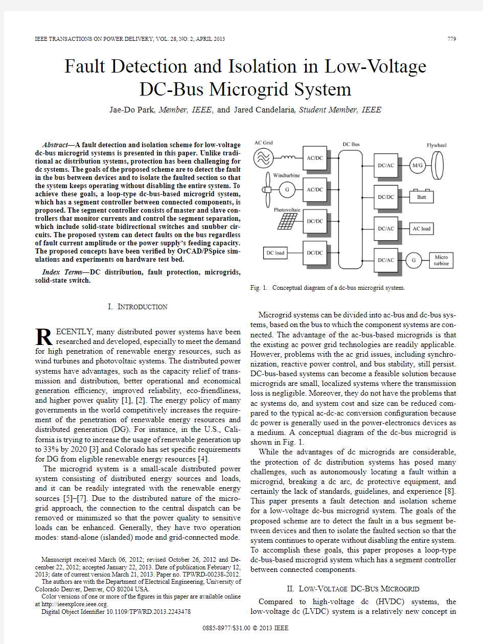
Fig.1.Conceptual diagram of a dc-bus microgrid system.
Microgrid systems can be divided into ac-bus and dc-bus sys-
tems,based on the bus to which the component systems are con-
nected.The advantage of the ac-bus-based microgrids is that
the existing ac power grid technologies are readily applicable.
However,problems with the ac grid issues,including synchro-
nization,reactive power control,and bus stability,still persist.
DC-bus-based systems can become a feasible solution because
microgrids are small,localized systems where the transmission
loss is negligible.Moreover,they do not have the problems that
ac systems do,and system cost and size can be reduced com-
pared to the typical ac-dc-ac conversion con?guration because
dc power is generally used in the power-electronics devices as
a medium.A conceptual diagram of the dc-bus microgrid is
shown in Fig.1.
While the advantages of dc microgrids are considerable,
the protection of dc distribution systems has posed many
challenges,such as autonomously locating a fault within a
microgrid,breaking a dc arc,dc protective equipment,and
certainly the lack of standards,guidelines,and experience[8].
This paper presents a fault detection and isolation scheme
for a low-voltage dc-bus microgrid system.The goals of the
proposed scheme are to detect the fault in a bus segment be-
tween devices and then to isolate the faulted section so that the
system continues to operate without disabling the entire system.
To accomplish these goals,this paper proposes a loop-type
dc-bus-based microgrid system which has a segment controller
between connected components.
II.L OW-V OLTAGE DC-B US M ICROGRID
Compared to high-voltage dc(HVDC)systems,the
low-voltage dc(LVDC)system is a relatively new concept in 0885-8977/$31.00?2013IEEE
Fig.2.Fault types in dc systems:(a)line-to-ground fault and(b)line-to-line fault.
electric power distribution.For small-scale systems,LVDC microgrids have many advantages over traditional ac distribu-tion systems.For both ac and dc microgrids,power-electronic converters are required to connect a variety of sources and loads to a common https://www.360docs.net/doc/f010706885.html,ing a dc bus requires fewer stages of conversion[8]–[10].Furthermore,the cables for the ac and dc power systems are chosen based upon the peak voltage of the system,and the power delivered by an ac system is based on the rms values,while the dc power is based on the constant peak voltage.Hence,the dc system can deliver times that of an ac system with the same cable.And dc systems do not suffer from the skin effect.Therefore,the dc system can utilize the entire cable,thus decreasing losses[9],[11].
Problems arise with dc microgrids when a system needs re-liable and versatile protection.AC systems have plenty of ex-perience and standards when it comes to system protection.DC systems do not have either of these advantages.The switchgear in dc systems must be very robust in order to handle the dc arc that is created during the interruption of fault currents.The pro-tection devices commercially available for low-voltage dc-bus systems are fuses and circuit breakers(CBs)[8].Traditional ac CB mechanisms,which rely on the natural zero crossing of the ac current to open the circuit,are inadequate to interrupt dc cur-rents.More important,the fault persists because the operating time of the CB increases.Allowing a fault current to persist on a microgrid bus could be catastrophic.
Because the microgrid systems need to be multiterminal, voltage-source converters(VSCs)must be used to interface different subsystems to bus.When a fault occurs on the dc side of a VSC system interfacing the ac source,the insulated-gate bipolar transistors(IGBTs)lose control and the freewheeling diodes become a bridge recti?er feeding the fault.The chal-lenge of protecting VSC systems is that the fault current must be detected and extinguished very quickly as the converter’s fault withstand rating is generally only twice the full-load rating [12].
III.F AULTS IN DC D ISTRIBUTION S YSTEMS
A.Possible Faults
Two types of faults exist in dc systems:1)line to line and2) line to ground,which can be seen in Fig.2.A line-to-line fault occurs when a path between the positive and negative line is cre-ated,short-circuiting them together.A line-to-ground fault oc-curs when either the positive or negative pole is short-circuited to ground.The line-to-ground faults are the most common types of faults in industrial distribution systems[13].
VSCs may experience internal switch faults that can cause a line-to-line short-circuit fault.This is a terminal fault for the device that cannot be cleared;in most cases,the device needs to be replaced.Hence,dc fuses would be a proper protection measure for this kind of fault.In ac systems,the ac-side CB will trip.
B.DC Fault Currents
When a fault occurs in a segment,the line current will split between load current and fault current
(1) The magnitude of the fault current depends on the fault loca-tion and resistance of the fault current path.If the impedance of fault path is low(e.g.,a line-to-ground fault with solid ground), the current polarity at the receiving end could be reversed,pre-venting the load from being supported at all.The fault current from the power source and bus capacitors can be given as fol-lows:
(2) where is the line voltage,and are the equivalent re-sistance and inductance including source,line and ground com-ponent,and and are the equivalent series resistance (ESR)and capacitance of bus capacitors,respectively.The time constant of the dc fault current is quite small because the line resistance of the dc system is negligible compared to ac power systems that have high reactance in the line.The bus voltage will drop or even collapse,depending on the capacity of the power supply and energy-storage device in the bus,and the grounding impedance.
C.Current Techniques
The common practice in dc power systems is not to install any protection on the dc side,and upon fault detection the ac CBs that link the ac and dc systems are opened[14],[15].A handshake method was suggested in[15]to isolate and locate the faulted segment:however,this method completely de-ener-gizes the dc system until the fault is removed and the systems can be re-energized.It works for HVDC and medium-voltage dc(MVDC)transmission systems where the dc system is a con-duit between the ac systems and loads.However,this method can create unnecessary outages in LVDC microgrids where mul-tiple sources and loads are connected to a common bus.Protec-tion techniques such as overcurrent[8],[9],[11],current time derivatives[8],undervoltage and directional protection[9]have been reported for LVDC distribution systems and dc shipboard power systems,but the dynamics of voltage and current on a faulted segment,especially when it is separated has not been extensively investigated.
Due to the limitations of fuses and traditional ac CBs in dc systems,a solid-state CB has become a valid option for dc power system protection.There are several alternatives for solid-state devices for the CBs,such as gate turn-off thyristors (GTOs),IGBTs,and insulated-gate commutated thyristors
PARK AND CANDELARIA:FAULT DETECTION AND ISOLATION IN LV DC-BUS MICROGRID SYSTEM781
(IGCTs).GTOs offer a high-voltage blocking capability and
a low on-state voltage,but suffer from slow switching speeds
[16].IGBTs are widely used in the low-voltage(1200V) systems and their advantages include fast interruption time and high short-circuit current withstanding capability[17]. However,high conduction loss is their disadvantage[18]. IGCTs have the lower conduction losses of a thyristor with the turnoff capability of a transistor.The IGCT has high voltage and current ratings as much as IGBTs,and the conduction loss is relatively low[19].In order for the microgrid bus to allow power?ow in either direction,the solid-state CB needs to be bidirectional.
Fuses or molded case CBs(MCCBs)can be utilized on dc systems[8].Fuses can be problematic as they will only trip the faulted line,leaving the unfaulted pole energized.Although this problem can be solved with MCCBs,the drawback of fuses and MCCBs is that neither can be controlled autonomously.In the event of a fault,human intervention is required to re-energize the system once the fault has been removed from the system. Another way to protect the system from excessive fault cur-rent is to limit the bus current under fault conditions.The fault current limiters can be used in conjunction with CBs.The ad-vantages of fault current limiting include ridethrough for tempo-rary faults,safe operation of switchgear,and system cost down by switchgear capacity reduction.Several devices have been uti-lized to limit the fault current,such as superconductors[20],sat-urated inductors[21],and power-electronics devices[22].
IV.P ROPOSED P ROTECTION S CHEME
A.Proposed Controller
This paper proposes a novel protection scheme for the dc-bus microgrid system.Instead of shutting down the whole system or limiting the bus current,the proposed scheme detects the fault and separates the faulted section so that the rest of the system keeps operating.The loop-type dc bus is suggested for the pro-posed scheme to make the system robust under faulted con-ditions.It has also been reported that the loop-type bus has a good system ef?ciency especially when the distribution line is not long[23].The entire loop will be divided into a series of segments between subsystems.Each segment will consist of a section of bus(positive and negative lines or positive line and ground)and a segment controller.The conceptual diagram of the proposed protection scheme is shown in Fig.3.The protec-tion system is shown only in segment A,and controllers on other segments are omitted.
The proposed protection system consists of one master con-troller,two slave controllers,and freewheeling branches be-tween each line and ground.The slave controllers read the cur-rent at each end of the bus segment connecting two components and send it to the master controller.They also operate the bidi-rectional solid-state switches on the bus segment and the free-wheeling branch according to the commands from the master controller.In the course of normal operations,the currents mea-sured at each end of the bus segment should be nearly iden-tical and the master controller sends commands to put the bus switches on normal
positions.Fig.3.Conceptual diagram of the proposed protection scheme.Protection con-trollers in segment B and C are
omitted.
Fig.4.Implementation of the proposed protection scheme.Arrows denote the switching action when a fault is detected.
B.Fault Detection and Isolation
The master controller monitors the difference of two current readings of slave controllers in a segment
(3) where and is the line current at each end of the bus segment.When the difference exceeds the threshold,the con-troller sends the appropriate commands to slave controllers so that the faulted segment can be separated from the system.Be-cause the proposed system uses the differential relaying prin-ciple monitoring only the relative difference of input and output current of a segment,it can detect the fault on the bus regardless of fault current amplitude or power supply’s feeding capacity. Once the faulted segment has been isolated,the bus voltage will be restored and remainder of the system can continue to operate on the loop-type bus.Even with multiple faulted segments,the system can operate partially if the segments from some power sources to loads are intact.The possibility of the fault around the device connection point can be minimized if the segment con-trollers are installed as close to the connection point as possible.
782IEEE TRANSACTIONS ON POWER DELIVERY,VOL.28,NO.2,APRIL
2013
Fig.5.Fault current and operation of the proposed protection scheme.(a)Line-to-ground fault between point A to G.(b)Isolated line-to-ground fault.(c)Line-to-line fault between point A and B.(d)Isolated line-to-line fault.
The implementation of the proposed protection scheme is shown in Fig.4,which shows the con?guration of segment A in Fig.3.Semiconductor-based bidirectional switches and diodes are used for segment separation and fault current freewheeling,respectively.In normal operations,switches are closed and diodes are open.When a fault occurs,the master controller detects it using the current information from the slave controllers and opens switches.Diodes are conducting at the same time to form a freewheeling path for fault currents so that the switches can open and the fault current can be extinguished through resistors.The segment con-trollers can detect the fault current of the line-to-ground fault (from point A or B to G)and line-to-line fault(from point A to B).A turnoff snubber circuit is included for switches to limit the voltage overshoot due to the line inductance.
The line-to-ground fault and the line-to-line fault are shown in Fig.5.It can be seen that the fault current is isolated and extinguished in the freewheeling loop.The freewheeling path impedance determines the extinction rate of the fault current, which can be given as follows:
(4) where and represent the resistance and inductance in the freewheeling path,respectively.
When a line-to-ground or a line-to-line fault occurs in the dis-tribution line,the bus voltage collapse would not allow the load to ride through if the current is limited from the source because of insuf?cient capacity.This is especially true for the VSC-in-terfaced microgrid systems.Furthermore,the fault current needs to be extinguished as quickly as possible even if the system has suf?cient current feeding capacity.Therefore,one of the best solutions would be to isolate the faulted line as soon as possible and continue operation with intact bus segments and subsys-tems.To achieve this,the segment controller needs to be capable of fast differential current detection and bus switch control.An automatic reclosing algorithm would be necessary for fault re-covery and more robust operation[24].
C.Snubber Circuit
Snubber circuits are indispensable to protect the solid-state CBs from the voltage transient due to the inductance of the bus cable.It is more so especially in a loop-type bus where the line inductance exists on both sides of the CB unlike the point-to-point-type system.Although the fault current needs to be interrupted as quickly as possible,the high could make the transient voltage catastrophically high for the solid-state switches.There are a couple of snubber circuit topologies to suppress the overvoltage at turn-off due to line inductance,such as decoupling capacitor,discharge restricted decoupling capacitor,discharge-charge-type RCD snubber, and discharge-suppressing-type RCD snubber[25].It has been reported that the decoupling capacitor has low losses but also oscillation issues,and RCD snubbers have higher losses but no oscillation problem and good for higher current applications[26].Since the solid-state CBs do not switch in
PARK AND CANDELARIA:FAULT DETECTION AND ISOLATION IN LV DC-BUS MICROGRID SYSTEM
783
Fig.6.Snubber circuits on the source side.(a)Discharge-suppressing-type RCD snubber.(b)Charge-discharge-type RCD snubber.
high frequency,charge-discharge-type RCD snubber has been chosen for better voltage suppression performance.Although the discharge-suppressing-type RCD snubber could eliminate the separate freewheeling path as can be seen in Fig.6(a), it would be dif?cult to handle bidirectional currents.The charge-discharge-type RCD snubber is shown in Fig.6(b).
A case of source-to-load power?ow has been considered. The capacitor in the charge-discharge-type snubber is fully dis-charged in normal operation when the switch is closed.When a fault is detected and the switch is trying to open,the diode
is forward biased and the snubber capacitor is charged to absorb the energy stored in the line inductance.The energy stored in the line inductance can be given as
(5)
where is the line current.The capacitance of snubber capac-itor to absorb the energy can be determined as follows:
(6)
(7) where is the allowable voltage overshoot over.The snubber resistor forms a discharging path when the switch is closed.Once the fault has been detected and separated,the system can check if the fault is cleared by reclosing test.When the switch is closed,most of the energy stored in the capacitor (6)should be discharged before the switch is re-opened in case the fault persists.Hence,the resistance can be determined by
(8) where is the percentage of stored energy to be discharged in time before the next switch opening.
D.Grounding
Grounding is one of the most important factors in the power system safety and protection.For a dc distribution system,the advantages of the grounding include predictable operating con-ditions,minimum voltage stress for the system components,and easier fault detection[27].The ground fault current can also be limited by using the resistance grounding.Since the typical power-electronics converters connected in the LVDC systems cannot feed large fault currents,it would be bene?cial to reduce the fault current to an appropriate level for detection and ex-tinction.However,some protective devices are still needed even with the resistance grounding schemes,because the fault current cannot be sustained.
The dc system grounding options are:1)solid grounding;2) low-resistance grounding;3)high-resistance grounding;and4) no grounding[13].Although ungrounded systems are used in some applications to avoid the effect of low-resistance pole-to-ground fault and stray current,ungrounded systems are sensitive to changes in the grounding plane and can be dangerous espe-cially under abnormal fault conditions[28].International stan-dard IEC60364de?nes three grounding systems.Low-voltage power systems(1kVac or1.5kVdc)using the two-letter codes TN,TT,and IT depending on how the source and conductive body of electric devices are connected to earth[29].The TN system ensures that distributed grounding and fault detection is straightforward but faults at a higher voltage level can increase the touch voltage.The TT system is easy to install and faults do not migrate to others but high-voltage stress is possible.The IT system has very low or even zero fault current and can op-erate with a single fault,but insulation monitoring is required and high fault current is possible with another ground fault[30]. It is a common practice to ground power subsystems at a single point and as close to the source as possible[27],like in a TN system.Multiple ground points in a TT system could form unnecessary circulating current paths.Possible grounding point for a dc system can be either one of the poles or the midpoint of the bus,and it has been reported that the balanced dc-side mid-point grounding signi?cantly reduces circulating current com-pared to the ac-side neutral-grounded system[27].Furthermore, it is safer because of lower ground potential compared to the di-rect pole grounding,and the ground impedance at the midpoint can limit the fault current under a safe level.The ground resistor can be used to detect the ground fault as well,although it is not able to identify the location of the fault because of the single ground point practices.
V.S IMULATION R ESULT
A computer simulation has been performed for a microgrid system that consists of three typical energy devices:a source,a load,and energy storage.They are connected as shown in Fig.7. Stiff dc power sources are assumed so that a constant fault cur-rent is fed by the sources without a voltage drop.A240V bipolar dc bus with200m bus cable segments[31]and a fault at the middle(100m)of the bus is simulated.Simulation parameters can be found in Table I.
A positive line-to-ground fault in the middle of the bus seg-ment A is simulated at1ms.Fig.8shows the source-and load-side current of a line-to-ground fault with and without pro-tection.It can be seen that the current from source increased to 180A after0.5msec.The fault current magnitude depends on the impedance of the fault path.The currents at each end of the segment which had been identical before fault show clear dif-ference after fault.Line-to-line fault current will be higher be-cause there is no resistance to limit it.Therefore,fast detection and isolation are critical.
It has been assumed in the simulation that the segment con-trollers can detect it and open/close solid-state CBs in250s.
784IEEE TRANSACTIONS ON POWER DELIVERY,VOL.28,NO.2,APRIL
2013
Fig.7.Simulation circuit for the line-to-ground fault in the three-node microgrid system that contains two sources and a load.A fault is simulated in the segment between source 1and load.
TABLE I
S IMULATION P
ARAMETERS
Considering the speed of current microcontrollers and switching devices,fast interruption in this speed range is feasible.Fig.8also shows that the fault currents are extinguished when the faulted segment is separated.
Fig.9shows the voltage across the load and the current in the freewheeling path.The ground fault pulls the positive pole voltage to zero,and the bipolar dc bus will experience a voltage offset on the faulted pole.However,the load voltage is quickly restored after the faulted segment has been separated.
Fig.10shows the voltage transient across the solid-state CB without and with the snubber circuits,respectively.It
also
Fig.8.Simulation:Source-side current (top)and load-side current (bottom)for a line-to-ground fault with and without protection.
shows the fault extinction in the freewheeling path.The voltage transient at turnoff due to the line inductance and high can be very high and it can easily damage the solid-state switch.It can also be seen that the voltage transient is suppressed by a snubber circuit at a tolerable level.
The protective devices in bus segments B and C have been omitted in this simulation because the proposed protective scheme that detects the difference in net current ?ow will not be triggered if there is no fault in the bus.This can be veri ?ed
PARK AND CANDELARIA:FAULT DETECTION AND ISOLATION IN LV DC-BUS MICROGRID SYSTEM
785
Fig.9.Simulation:Load voltage with and without protection (top)and current in a freewheeling path in the proposed scheme
(bottom).
Fig.10.Simulation:Voltage across switch at turnoff without (top)and
with (bottom)the snubber.
by the currents ?owing into and out of the intact bus segment C shown in Fig.11.Even with the transient caused by the fault on the bus segment A,the incoming and outgoing currents of segment C are identical.The proposed scheme that detects the current difference is robust to common-mode noise and transient due to a fault.
VI.E XPERIMENTAL V ALIDATION
A lab-scale experiment setup in about 6:1scale from the sim-ulation circuit has been built to validate the feasibility of the pro-posed protection scheme with actual hardware.The setup has a source-load-storage structure of Fig.3,but only with positive pole and ground to simulate a line-to-ground fault.Two chan-nels of 30-V 3-A power supply Instek GPC-3030D have been utilized for 20-V source and energy storage,and 12.5-resis-tive load is used.Each source supplies about 1A of load current in normal operation.Three 15-H inductors and six 220-pF ca-pacitors are installed in the positive line to simulate the line in-ductance and stray capacitance,respectively.But no resistance has been added in the bus due to the low current capacity of the power supply.Two IXYS 600V IGBT IXGN60N60C2D1mod-ules have been used to make a bidirectional solid-state CB
and
Fig.11.Simulation:Voltage of bus segments B and C (top)and currents of
segment
C
and (bottom).Intact segment C currents (incoming)and (outgoing)are identical.
Fig.12.Schematic of the experimental setup.
the same IGBT has been utilized to form the ground fault path.IGCTs can be considered for lower conduction losses.The free-wheeling path has an IR diode T40HF60and a 2-freewheeling https://www.360docs.net/doc/f010706885.html,ing a diode in the freewheeling branch simpli ?es the control circuits and it can be used for the line-to-ground fault protection.The RCD snubber circuit is attached to the IGBT with a 10-F capacitor,a 12-resistor,and a diode T40HF60.The circuit parameters have not been scaled down because of the inductance in the power supplies.The schematic of the ex-perimental test bed is shown in Fig.12.
The differential protection algorithm described in Section IV-B is implemented in TI’s TMS320F28335dig-ital signal processing (DSP)microcontroller.As shown in Fig.12,the controller monitors the source and load-side current using Tektronics A622current probes through analog-to-digital channels of DSP,and controls the IGBT CBs.A threshold of 20%has been used for (3)in the experiments,but the threshold level may vary depending on bus conditions to increase sensi-tivity or to avoid malfunction.The controller sends out a digital output to the gate driver board,which generates isolated gating signal using optocoupler HCPL-3120.In this experiment,the analog-digital conversion of the current measurement is done in the 100-s interrupt service routine.Although the controller takes the analog signal directly from the current sensors because of the small size of the test bed,digital communication between the master and slave controller should be considered for larger
786IEEE TRANSACTIONS ON POWER DELIVERY,VOL.28,NO.2,APRIL
2013
Fig.13.Experimental test bed and DSP
controller.
Fig.14.Experiment:Source-side current (top)and load-side current
(bottom)with and without protection.
scale systems.Distributed control without the master controller can be possible if the two slave controllers are communicating with each other.The experimental test bed is shown in Fig.13.A line-to-ground fault has been experimentally tested.In normal steady-state condition,the source power supply supplies 20W of power (20V ,1A)to the load and the power-supply simulating energy storage monitors the bus voltage.When the ground fault IGBT is turned on,two power-supply channels feed the fault current,and the segment controller measures the current shown in Fig.14.The difference is quite large because the direction of the load-side current is reversed unlike the simulation due to the low fault impedance.The controller readily detects the difference of the bus currents and isolates the faulted segment immediately.It turned out that the power supply can feed about 40-A peak transient fault current for a couple hundred microseconds before each channel settles down to 3A of the power supply’s rated current.It should be noted that this power-supply characteristic makes the waveform of experimental fault current different from that of the simulation in Fig.8.
Fig.14shows that the fault current is extinguished to zero as simulated.The fault current extinction time,which depends on the freewheeling path impedance,was about 100s in
this
Fig.15.Experiment:Load voltage with and without protection (top)and cur-rent in the freewheeling path in the proposed scheme
(bottom).
Fig.16.Experiment:IGBT collector-emitter voltage without (top)and
with (bottom)the snubber circuit.
experiment.Without protection,6-A fault current ?ows from two power-supply channels after transient.Fig.15shows that the load voltage is restored to a normal level quickly after the faulted segment is separated;otherwise,it collapses to a low voltage without the protection system.Fig.16shows that the snubber circuit effectively suppresses the voltage overshoot and oscillation across the IGBT.
VII.C ONCLUSION
This paper has presented a fault detection and isolation scheme for the low-voltage dc-bus microgrid system.The proposed protection scheme consists of segment controllers capable of detecting abnormal fault current in the bus and separating the faulted segment to avoid the entire system shutdown.A loop-type dc-bus-based microgrid system with segment controllers between connected components and the freewheeling branch has been proposed.The proposed pro-tection concepts have been validated by computer simulations and experiments.A prototype system with a segment controller that consists of master and slave controllers has been tested on an actual hardware test bed and it has shown successful fault detection and isolation capability.The proposed scheme can be applied to dc power systems,such as Green Buildings,
PARK AND CANDELARIA:FAULT DETECTION AND ISOLATION IN LV DC-BUS MICROGRID SYSTEM787
with sustainable energy resources and data centers with a server array.Challenges,such as a reduction of conduction loss in the solid-state CBs and fault ridethrough capability,and fault-location techniques need to be investigated.
R EFERENCES
[1]R.Dugan and T.McDermott,“Distributed generation,”IEEE Ind.
Appl.Mag.,vol.8,no.2,pp.19–25,Mar./Apr.2002.
[2]F.Blaabjerg,R.Teodorescu,M.Liserre,and A.Timbus,“Overview
of control and grid synchronization for distributed power generation
systems,”IEEE Trans.Ind.Electron.,vol.53,no.5,pp.1398–1407,
Oct.2006.
[3]U.S.Department of Energy,(2009).States With Renewable Portfolio
Standards.[Online].Available:https://www.360docs.net/doc/f010706885.html,/renewables
[4]U.S.Department of Energy Energy Ef?ciency and Renewable Energy
News,(2010).Colorado Boosts its Renewable Energy Requirement to
30%by2020.[Online].Available:https://www.360docs.net/doc/f010706885.html,/news/
news\_detail.cfm/news\_id=15878
[5]https://www.360docs.net/doc/f010706885.html,sseter and P.Paigi,“Microgrid:A conceptual solution,”in
Proc.35th Annu.IEEE Power Electron.Specialists Conf.,2004,pp.
4285–4290.
[6]H.Nikkhajoei and https://www.360docs.net/doc/f010706885.html,sseter,“Distributed generation interface to
the CERTS microgrid,”IEEE Trans.Power Del.,vol.24,no.3,pp.
1598–1608,Jul.2009.
[7]F.Katiraei,R.Iravani,N.Hatziargyriou,and A.Dimeas,“Microgrids
management,”IEEE Power Energy Mag.,vol.6,no.3,pp.54–65,May/
Jun.2008.
[8]D.Salomonsson,L.Soder,and A.Sannino,“Protection of low-voltage
DC microgrids,”IEEE Trans.Power Del.,vol.24,no.3,pp.
1045–1053,Jul.2009.
[9]M.Saeedifard,M.Graovac,R.Dias,and R.Iravani,“DC power sys-
tems:Challenges and opportunities,”in Proc.IEEE Power Energy Soc.
Gen.Meeting,July2010,pp.1–7.
[10]R.Cuzner and G.Venkataramanan,“The status of DC micro-grid pro-
tection,”in Proc.IEEE Ind.Appl.Soc.Annu.Meeting,Oct.2008,pp.
1–8.
[11]P.Salonen,P.Nuutinen,P.Peltoniemi,and J.Partanen,“LVDC dis-
tribution system protection:Solutions,implementation and measure-
ments,”in Proc.13th Eur.Conf.Power Electron.Appl.,2009,pp.1–10.
[12]J.Candelaria and J.-D.Park,“VSC-HVDC system protection:A re-
view of current methods,”in Proc.IEEE/Power Energy Soc.Power
Syst.Conf.Expo.,Mar.2011,pp.1–7.
[13]J.Das and R.Osman,“Grounding of AC and DC low-voltage and
medium-voltage drive systems,”IEEE Trans.Ind.Appl.,vol.34,no.
1,pp.205–216,Jan./Feb.1998.
[14]P.Cairoli,R.Dougal,U.Ghisla,and I.Kondratiev,“Power sequencing
approach to fault isolation in dc systems:In?uence of system parame-
ters,”in Proc.IEEE Energy Convers.Congr.Expo.,2010,pp.72–78.
[15]L.Tang and B.Ooi,“Locating and isolating DC faults in multi-terminal
DC systems,”IEEE Trans.Power Del.,vol.22,no.3,pp.1877–1884,
Jul.2007.
[16]H.Iwamoto,K.Satoh,M.Yamamoto,and A.Kawakami,“High-power
semiconductor device:A symmetric gate commutated turn-off
thyristor,”Proc.Inst.Elect.Eng.,Elect.Power Appl.,vol.148,no.4,
pp.363–368,Jul.2001.
[17]Y.Ito,Y.Zhongqing,and H.Akagi,“DC micro-grid based distribu-
tion power generation system,”presented at the4th Int.Conf.Power
Electron.Motion Control,Xi’an,China,Aug.2004.
[18]R.Schmerda,S.Krstic,E.Wellner,and A.Bendre,“IGCTs vs.IGBTs
for circuit breakers in advanced ship electrical systems,”in Proc.IEEE
Electric Ship Technol.Symp.,Apr.2009,pp.400–405.
[19]P.Steimer,O.Apeldoorn,E.Carroll,and A.Nagel,“IGCT technology
baseline and future opportunities,”in Proc.IEEE/Power Energy Soc.
Transm.Distrib.Conf.Expo.,2001,vol.2,pp.1182–1187.
[20]F.Luo,J.Chen,X.Lin,Y.Kang,and S.Duan,“A novel solid state fault
current limiter for DC power distribution network,”in Proc.IEEE23rd
Annu.Appl.Power Electron.Conf.Expo.,Feb.2008,pp.1284–1289.
[21]W.Fei,Y.Zhang,and Z.Lu,“Novel bridge-type FCL based on self-
turnoff devices for three-phase power systems,”IEEE Trans.Power
Del.,vol.23,no.4,pp.2068–2078,Oct.2008.
[22]U.Ghisla,I.Kondratiev,and R.Dougal,“Branch circuit protection for
DC systems,”in Proc.IEEE Elect.Ship Technol.Symp.,Apr.2011,pp.
234–239.
[23]M.Saisho,T.Ise,and K.Tsuji,“Con?guration of DC loop type
quality control center,”in Proc.Power Convers.Conf.,2002,vol.2,
pp.434–439.
[24]J.Machowski,J.Bialek,and J.Bumby,Power System Dynamics:Sta-
bility and Control.Hoboken,NJ:Wiley,2011.
[25]N.Mohan,T.Undeland,and W.Robbins,Power Electronics Con-
verters,Applications,Design,3rd ed.Hoboken,NJ:Wiley,2003.
[26]Y.Zhang,S.Sobhani,and R.Chokhawala,Snubber considerations for
IGBT applications,2002.[Online].Available:https://www.360docs.net/doc/f010706885.html,/technical-
info/designtp/tpap-5.pdf
[27]B.Jacobson and J.Walker,“Grounding considerations for dc and
mixed dc and ac power systems,”Naval Eng.J.,vol.119,no.2,pp.
49–62,October2007.
[28]D.Paul,“DC traction power system grounding,”IEEE Trans.Ind.
Appl.,vol.38,no.3,pp.818–824,May/Jun.2002.
[29]IEC60364-1Low-Voltage Electrical Installations—Part1:Funda-
mental Principles,Assessment of General Characteristics,De?nitions,
IEC60364-1,2005.
[30]R.Kamel,A.Chaouaski,and K.Nagasaka,“Design and testing of three
earthing systems for micro-grid protection during the islanding mode,”
Smart Grid Renew.Energy,vol.1,pp.132–142,Sep.2010.
[31]“Transmission Line Reference Book345kV and Above,”Elect.Power
Res.Inst.,
1987.
Jae-Do Park(M’07)received the Ph.D.degree in
electrical engineering from the Pennsylvania State
University,University Park,in2007.
Currently,he is an Assistant Professor of Elec-
trical Engineering at the University of Colorado
Denver,Denver,CO,USA.Prior to his arrival at
the University of Colorado Denver,he was Manager
of Software and Controls for Pentadyne Power
Corporation,CA,where he took charge of control
algorithm design and software development for the
high-speed?ywheel energy-storage system.He is interested in various energy and power system research and education topics, including electric machines and drives,energy-storage and harvesting systems, renewable energy sources,grid-interactive distributed generation,microturbine control,and microgrid
systems.
Jared Candelaria(S’10)is currently pursuing the
M.S.E.E.degree in power options at the University
of Colorado Denver,Denver,CO,USA.
He is an Electrical Engineer at NEI Electric Power
Engineering,Arvada,CO.His duties at NEI include
arc?ash,interconnection of distributed generation,
supervisory control and data acquisition,substation
design,industrial design,and protective relaying.
His research interests include power systems appli-
cations,power system protection,and HVDC.
Mr.Candelaria is a registered E.I.T.in the state of Colorado.