Lin Chen's CFOP
cfop三阶魔方速拧公式oll19
cfop三阶魔方速拧公式oll19CFOP(Cross-F2L-OLL-PLL)是一种常用于解魔方的方法,其中OLL (Orientation of the Last Layer)是指最后一层的定位。
OLL19是OLL阶段中的一个公式,用于完成最后一层的定位。
下面将详细介绍OLL19公式及其使用方法。
OLL19公式的全称为OLL 1-9-2,也被称为"鱼形公式"。
它的作用是将魔方最后一层的棱块和角块进行定位,使它们回到正确的位置和朝向。
使用OLL19公式前,需要先完成魔方的底层十字和F2L (First 2 Layers)步骤。
我们需要将魔方的白色十字放在底面,并将底层四个角块和中层四个棱块放在正确的位置上。
接下来,进行F2L步骤,将中层的四个角块和四个棱块与顶层的边缘块配对,并放在正确的位置上。
完成F2L后,我们进入OLL阶段。
OLL19公式的步骤如下:1. 将魔方顶面转到正确的面,使得其中两个棱块形成一个"鱼形"的图案。
这两个棱块可以是相邻的或者对面的。
这一步的目的是为了将这两个棱块定位到最后一层的正确位置。
2. 将魔方顶面转到正确的面,使得一个角块形成"鱼形"图案的其中一条边。
这一步的目的是为了将这个角块定位到最后一层的正确位置。
3. 将魔方顶面转到正确的面,使得一个角块形成"鱼形"图案的另一条边。
这一步的目的是为了将这个角块定位到最后一层的正确位置。
使用OLL19公式需要一定的练习和记忆,但一旦熟悉了这个公式,定位最后一层的棱块和角块将变得更加高效和准确。
除了OLL19公式,CFOP方法还包括PLL(Permutation of the Last Layer)步骤,用于完成最后一层的排列。
PLL步骤主要包括角块的位置和朝向的调整,以及棱块的位置的调整。
完成PLL步骤后,魔方的还原就完成了。
总结一下,OLL19是CFOP方法中用于定位魔方最后一层的一个公式。
2020年第43卷总目次

Ⅲ
船用锅炉汽包水位内模滑模控制………………………………………………… 段蒙蒙ꎬ甘辉兵 ( 3. 83 )
三峡升船机变频器 IGBT 路故障诊断 ……………………… 孟令琦ꎬ高 岚ꎬ李 然ꎬ朱汉华 ( 3. 89 )
定航线下考虑 ECA 的船舶航速多目标优化模型 …………… 甘浪雄ꎬ卢天赋ꎬ郑元洲ꎬ束亚清 ( 3. 15 )
改进二阶灰色极限学习机在船舶运动预报中的应用………… 孙 珽ꎬ徐东星ꎬ苌占星ꎬ叶 进 ( 3. 20 )
Ⅱ
规则约束下基于深度强化学习的船舶避碰方法
………………………………… 周双林ꎬ杨 星ꎬ刘克中ꎬ熊 勇ꎬ吴晓烈ꎬ刘炯炯ꎬ王伟强 ( 3. 27 )
船用起重机吊索张力建模与计算机数值仿真 ………………………… 郑民民ꎬ张秀风ꎬ王任大 ( 4. 94 )
约束规划求解自动化集装箱码头轨道吊调度 ………………………… 丁 一ꎬ田 亮ꎬ林国龙 ( 4. 99 )
航海气象与环保
162 kW 柴油机排气海水脱硫性能
基于模糊 ̄粒子群算法的舰船主锅炉燃烧控制 ……… 毛世聪ꎬ汤旭晶ꎬ汪 恬ꎬ李 军ꎬ袁成清 ( 1. 88 )
多能源集成控制的船舶用微电网系统频率优化……………… 张智华ꎬ李胜永ꎬ季本山ꎬ赵 建 ( 1. 95 )
基于特征模型的疏浚过程中泥浆浓度控制系统设计………… 朱师伦ꎬ高 岚ꎬ徐合力ꎬ潘成广 ( 2. 74 )
基于卷积神经网络的航标图像同态滤波去雾 …………………………………………… 陈遵科 ( 4. 84 )
船用北斗导航系统终端定位性能的检测验证 …………………………………………… 吴晓明 ( 4. 89 )
CFO也是首席聚焦(Focal)官(一)

CFO也是首席聚焦(Focal)官(一)为期两天的中国首届CFO高峰论坛暨“2004年中国CFO年度人物”颁奖典礼2月27日在北京国家会计学院落下帷幕。
作为国内财务管理界的最高盛会,此次论坛聚集了来自国内上市公司的众多首席财务官(ChieffinancialOfficer)。
与会者通过交流发现,在我国上市公司,无论是CFO的能力,还是在企业中的地位,都已经得到显著提高。
“CFO目前已经是现代公司里面最重要、最具有价值的顶尖管理职位之一,是一个穿插在金融市场操作和公司内部财务管理之间举足轻重的角色。
”北京国家会计学院院长陈小悦如是说。
CFO是“首席聚焦官”在这次论坛上,很多CFO笑言自己是“首席聚焦官”(ChiefFocalOfficer),他们认为自己已经站在了企业管理层的中心阵营,但在其能力和地位得到提升的同时,伴随而来的还有日益加重的压力。
东软集团副总裁兼CFO王莉在大会发言时谈到:“8年财务总监的工作让我发现,CFO总是站在矛盾的焦点上,需要处理一些很棘手的问题,然后总是被人误解、被人指责。
很多时候都要跟那些CXO争得面红耳赤,甚至有默默流泪的时候。
做这样的工作,需要有甘愿做绿叶的心态,需要有极强的抗击打能力;但是我同时又很满足,因为可以看到企业在自己的管理下能够不断前进。
我想这种感觉就是痛并快乐着吧。
”在东软集团迅速成长的8年中,王莉致力于设计制度、制定规则、建设队伍,同时介入经营、业务变革,呼吁建立价值管理体系和风险评价体系,实施ERP推行智能化管理,到最后建立战略决策支持系统,保障目标的完成。
在取得成绩的同时,王莉发现自己作为CFO的角色也在逐渐变化———从简单执行到参与战略制定,从财务管理到协调团队作战,挑战与阻力到处存在。
这样的转变在很多CFO身上都有发生。
华润集团财务总监蒋伟说,很长时间以来,公司很多人把他当成“警察”,因为财务系统和企业各个部门都有直接联系,可以非常清楚地知道很多真实情况,公司高层也只把财务系统作为执行系统看待。
CFO背景特征与审计费用

CFO背景特征与审计费用一、引言随着科技和经济的飞速发展,企业的经营环境越来越复杂,管理层对财务信息的准确性和真实性要求也越来越高,审计费用作为财务信息真实可靠性的保证,越来越受到企业关注。
CFO作为企业财务的核心管理者,其背景特征对审计费用可能产生一定的影响。
本文将从CFO的背景特征和审计费用之间的联系进行分析,旨在探讨CFO的背景特征对审计费用的影响。
二、CFO背景特征1. 学历CFO的学历是其背景特征中的一个重要因素。
一般来说,拥有高学历的CFO可能在财务管理、风险评估等方面有更为深入的理解和把握,能够对企业的财务信息进行有效的管理和控制,因此相对而言能够提高财务信息的真实性和可靠性,从而降低审计费用。
有些学历较低但具有丰富经验的CFO也能够在财务管理方面表现出色,因此并非所有情况下学历高低都能决定审计费用的高低。
2. 职业背景CFO的职业背景也是审计费用的影响因素之一。
如果CFO曾在知名的财务公司或者是国内外知名企业担任过重要职位,那么其在财务管理和风险评估方面可能具有较高的能力和经验,能够更好地管理企业的财务信息,并为审计工作提供更准确的数据,从而降低审计费用。
反之,如果CFO的职业背景比较简单或者是在一些小公司或行业内比较小众的企业工作过,那么其在财务管理方面可能相对较弱,需要审计师花费更多的时间和精力来对财务信息进行核实,因此可能会增加审计费用。
3. 技能和经验在实际的企业管理中,CFO应该根据自身的背景特征,不断提升自己的财务管理和风险评估能力,从而提高对企业财务信息的管理水平,降低审计费用,为企业财务管理工作做出更大的贡献。
四、总结CFO的背景特征对审计费用可能产生一定的影响,包括学历、职业背景、技能和经验、行业背景等因素。
这些因素都决定了CFO在财务管理和风险评估方面的能力和水平,进而可能影响审计费用。
对于企业而言,应该根据CFO的背景特征,合理安排审计工作,为审计师提供准确的数据,从而降低审计费用,并且对CFO进行进一步的培训和提升,提高其财务管理和风险评估的能力,降低审计费用,为企业的可持续发展提供保障。
1999.Multilevel Hypergraph Partitioning__Applications in VLSI Domain

Multilevel Hypergraph Partitioning:Applications in VLSI DomainGeorge Karypis,Rajat Aggarwal,Vipin Kumar,Senior Member,IEEE,and Shashi Shekhar,Senior Member,IEEE Abstract—In this paper,we present a new hypergraph-partitioning algorithm that is based on the multilevel paradigm.In the multilevel paradigm,a sequence of successivelycoarser hypergraphs is constructed.A bisection of the smallesthypergraph is computed and it is used to obtain a bisection of theoriginal hypergraph by successively projecting and refining thebisection to the next levelfiner hypergraph.We have developednew hypergraph coarsening strategies within the multilevelframework.We evaluate their performance both in terms of thesize of the hyperedge cut on the bisection,as well as on the runtime for a number of very large scale integration circuits.Ourexperiments show that our multilevel hypergraph-partitioningalgorithm produces high-quality partitioning in a relatively smallamount of time.The quality of the partitionings produced by ourscheme are on the average6%–23%better than those producedby other state-of-the-art schemes.Furthermore,our partitioningalgorithm is significantly faster,often requiring4–10times lesstime than that required by the other schemes.Our multilevelhypergraph-partitioning algorithm scales very well for largehypergraphs.Hypergraphs with over100000vertices can bebisected in a few minutes on today’s workstations.Also,on thelarge hypergraphs,our scheme outperforms other schemes(inhyperedge cut)quite consistently with larger margins(9%–30%).Index Terms—Circuit partitioning,hypergraph partitioning,multilevel algorithms.I.I NTRODUCTIONH YPERGRAPH partitioning is an important problem withextensive application to many areas,including very largescale integration(VLSI)design[1],efficient storage of largedatabases on disks[2],and data mining[3].The problemis to partition the vertices of a hypergraphintois definedas a set ofvertices[4],and the size ofa hyperedge is the cardinality of this subset.Manuscript received April29,1997;revised March23,1998.This workwas supported under IBM Partnership Award NSF CCR-9423082,by theArmy Research Office under Contract DA/DAAH04-95-1-0538,and by theArmy High Performance Computing Research Center,the Department of theArmy,Army Research Laboratory Cooperative Agreement DAAH04-95-2-0003/Contract DAAH04-95-C-0008.G.Karypis,V.Kumar,and S.Shekhar are with the Department of ComputerScience and Engineering,Minneapolis,University of Minnesota,Minneapolis,MN55455-0159USA.R.Aggarwal is with the Lattice Semiconductor Corporation,Milpitas,CA95131USA.Publisher Item Identifier S1063-8210(99)00695-2.During the course of VLSI circuit design and synthesis,itis important to be able to divide the system specification intoclusters so that the inter-cluster connections are minimized.This step has many applications including design packaging,HDL-based synthesis,design optimization,rapid prototyping,simulation,and testing.In particular,many rapid prototyp-ing systems use partitioning to map a complex circuit ontohundreds of interconnectedfield-programmable gate arrays(FPGA’s).Such partitioning instances are challenging becausethe timing,area,and input/output(I/O)resource utilizationmust satisfy hard device-specific constraints.For example,ifthe number of signal nets leaving any one of the clustersis greater than the number of signal p-i-n’s available in theFPGA,then this cluster cannot be implemented using a singleFPGA.In this case,the circuit needs to be further partitioned,and thus implemented using multiple FPGA’s.Hypergraphscan be used to naturally represent a VLSI circuit.The verticesof the hypergraph can be used to represent the cells of thecircuit,and the hyperedges can be used to represent the netsconnecting these cells.A high quality hypergraph-partitioningalgorithm greatly affects the feasibility,quality,and cost ofthe resulting system.A.Related WorkThe problem of computing an optimal bisection of a hy-pergraph is at least NP-hard[5].However,because of theimportance of the problem in many application areas,manyheuristic algorithms have been developed.The survey byAlpert and Khang[1]provides a detailed description andcomparison of such various schemes.In a widely used class ofiterative refinement partitioning algorithms,an initial bisectionis computed(often obtained randomly)and then the partitionis refined by repeatedly moving vertices between the twoparts to reduce the hyperedge cut.These algorithms oftenuse the Schweikert–Kernighan heuristic[6](an extension ofthe Kernighan–Lin(KL)heuristic[7]for hypergraphs),or thefaster Fiduccia–Mattheyses(FM)[8]refinement heuristic,toiteratively improve the quality of the partition.In all of thesemethods(sometimes also called KLFM schemes),a vertex ismoved(or a vertex pair is swapped)if it produces the greatestreduction in the edge cuts,which is also called the gain formoving the vertex.The partition produced by these methodsis often poor,especially for larger hypergraphs.Hence,thesealgorithms have been extended in a number of ways[9]–[12].Krishnamurthy[9]tried to introduce intelligence in the tie-breaking process from among the many possible moves withthe same high gain.He used a Look Ahead()algorithm,which looks ahead uptoa move.PROP [11],introduced by Dutt and Deng,used a probabilistic gain computation model for deciding which vertices need to move across the partition line.These schemes tend to enhance the performance of the basic KLFM family of refinement algorithms,at the expense of increased run time.Dutt and Deng [12]proposed two new methods,namely,CLIP and CDIP,for computing the gains of hyperedges that contain more than one node on either side of the partition boundary.CDIP in conjunctionwithand CLIP in conjunction with PROP are two schemes that have shown the best results in their experiments.Another class of hypergraph-partitioning algorithms [13]–[16]performs partitioning in two phases.In the first phase,the hypergraph is coarsened to form a small hypergraph,and then the FM algorithm is used to bisect the small hypergraph.In the second phase,these algorithms use the bisection of this contracted hypergraph to obtain a bisection of the original hypergraph.Since FM refinement is done only on the small coarse hypergraph,this step is usually fast,but the overall performance of such a scheme depends upon the quality of the coarsening method.In many schemes,the projected partition is further improved using the FM refinement scheme [15].Recently,a new class of partitioning algorithms was devel-oped [17]–[20]based upon the multilevel paradigm.In these algorithms,a sequence of successively smaller (coarser)graphs is constructed.A bisection of the smallest graph is computed.This bisection is now successively projected to the next-level finer graph and,at each level,an iterative refinement algorithm such as KLFM is used to further improve the bisection.The various phases of multilevel bisection are illustrated in Fig.1.Iterative refinement schemes such as KLFM become quite powerful in this multilevel context for the following reason.First,the movement of a single node across a partition bound-ary in a coarse graph can lead to the movement of a large num-ber of related nodes in the original graph.Second,the refined partitioning projected to the next level serves as an excellent initial partitioning for the KL or FM refinement algorithms.This paradigm was independently studied by Bui and Jones [17]in the context of computing fill-reducing matrix reorder-ing,by Hendrickson and Leland [18]in the context of finite-element mesh-partitioning,and by Hauck and Borriello (called Optimized KLFM)[20],and by Cong and Smith [19]for hy-pergraph partitioning.Karypis and Kumar extensively studied this paradigm in [21]and [22]for the partitioning of graphs.They presented new graph coarsening schemes for which even a good bisection of the coarsest graph is a pretty good bisec-tion of the original graph.This makes the overall multilevel paradigm even more robust.Furthermore,it allows the use of simplified variants of KLFM refinement schemes during the uncoarsening phase,which significantly speeds up the refine-ment process without compromising overall quality.METIS [21],a multilevel graph partitioning algorithm based upon this work,routinely finds substantially better bisections and is often two orders of magnitude faster than the hitherto state-of-the-art spectral-based bisection techniques [23],[24]for graphs.The improved coarsening schemes of METIS work only for graphs and are not directly applicable to hypergraphs.IftheFig.1.The various phases of the multilevel graph bisection.During the coarsening phase,the size of the graph is successively decreased;during the initial partitioning phase,a bisection of the smaller graph is computed,and during the uncoarsening and refinement phase,the bisection is successively refined as it is projected to the larger graphs.During the uncoarsening and refinement phase,the dashed lines indicate projected partitionings and dark solid lines indicate partitionings that were produced after refinement.G 0is the given graph,which is the finest graph.G i +1is the next level coarser graph of G i ,and vice versa,G i is the next level finer graph of G i +1.G 4is the coarsest graph.hypergraph is first converted into a graph (by replacing each hyperedge by a set of regular edges),then METIS [21]can be used to compute a partitioning of this graph.This technique was investigated by Alpert and Khang [25]in their algorithm called GMetis.They converted hypergraphs to graphs by simply replacing each hyperedge with a clique,and then they dropped many edges from each clique randomly.They used METIS to compute a partitioning of each such random graph and then selected the best of these partitionings.Their results show that reasonably good partitionings can be obtained in a reasonable amount of time for a variety of benchmark problems.In particular,the performance of their resulting scheme is comparable to other state-of-the art schemes such as PARABOLI [26],PROP [11],and the multilevel hypergraph partitioner from Hauck and Borriello [20].The conversion of a hypergraph into a graph by replacing each hyperedge with a clique does not result in an equivalent representation since high-quality partitionings of the resulting graph do not necessarily lead to high-quality partitionings of the hypergraph.The standard hyperedge-to-edge conversion [27]assigns a uniform weightofisthe of the hyperedge,i.e.,thenumber of vertices in the hyperedge.However,the fundamen-tal problem associated with replacing a hyperedge by its clique is that there exists no scheme to assign weight to the edges of the clique that can correctly capture the cost of cutting this hyperedge [28].This hinders the partitioning refinement algo-rithm since vertices are moved between partitions depending on how much this reduces the number of edges they cut in the converted graph,whereas the real objective is to minimize the number of hyperedges cut in the original hypergraph.Furthermore,the hyperedge-to-clique conversion destroys the natural sparsity of the hypergraph,significantly increasing theKARYPIS et al.:MULTILEVEL HYPERGRAPH PARTITIONING:APPLICATIONS IN VLSI DOMAIN 71run time of the partitioning algorithm.Alpert and Khang [25]solved this problem by dropping many edges of the clique randomly,but this makes the graph representation even less accurate.A better approach is to develop coarsening and refinement schemes that operate directly on the hypergraph.Note that the multilevel scheme by Hauck and Borriello [20]operates directly on hypergraphs and,thus,is able to perform accurate refinement during the uncoarsening phase.However,all coarsening schemes studied in [20]are edge-oriented;i.e.,they only merge pairs of nodes to construct coarser graphs.Hence,despite a powerful refinement scheme (FM with theuse oflook-ahead)during the uncoarsening phase,their performance is only as good as that of GMetis [25].B.Our ContributionsIn this paper,we present a multilevel hypergraph-partitioning algorithm hMETIS that operates directly on the hypergraphs.A key contribution of our work is the development of new hypergraph coarsening schemes that allow the multilevel paradigm to provide high-quality partitions quite consistently.The use of these powerful coarsening schemes also allows the refinement process to be simplified considerably (even beyond plain FM refinement),making the multilevel scheme quite fast.We investigate various algorithms for the coarsening and uncoarsening phases which operate on the hypergraphs without converting them into graphs.We have also developed new multiphase refinement schemes(-cycles)based on the multilevel paradigm.These schemes take an initial partition as input and try to improve them using the multilevel scheme.These multiphase schemes further reduce the run times,as well as improve the solution quality.We evaluate their performance both in terms of the size of the hyperedge cut on the bisection,as well as on run time on a number of VLSI circuits.Our experiments show that our multilevel hypergraph-partitioning algorithm produces high-quality partitioning in a relatively small amount of time.The quality of the partitionings produced by our scheme are on the average 6%–23%better than those produced by other state-of-the-art schemes [11],[12],[25],[26],[29].The difference in quality over other schemes becomes even greater for larger hypergraphs.Furthermore,our partitioning algorithm is significantly faster,often requiring 4–10times less time than that required by the other schemes.For many circuits in the well-known ACM/SIGDA benchmark set [30],our scheme is able to find better partitionings than those reported in the literature for any other hypergraph-partitioning algorithm.The remainder of this paper is organized as follows.Section II describes the different algorithms used in the three phases of our multilevel hypergraph-partitioning algorithm.Section III describes a new partitioning refinement algorithm based on the multilevel paradigm.Section IV compares the results produced by our algorithm to those produced by earlier hypergraph-partitioning algorithms.II.M ULTILEVEL H YPERGRAPH B ISECTIONWe now present the framework of hMETIS ,in which the coarsening and refinement scheme work directly with hyper-edges without using the clique representation to transform them into edges.We have developed new algorithms for both the phases,which,in conjunction,are capable of delivering very good quality solutions.A.Coarsening PhaseDuring the coarsening phase,a sequence of successively smaller hypergraphs are constructed.As in the case of mul-tilevel graph bisection,the purpose of coarsening is to create a small hypergraph,such that a good bisection of the small hypergraph is not significantly worse than the bisection di-rectly obtained for the original hypergraph.In addition to that,hypergraph coarsening also helps in successively reducing the sizes of the hyperedges.That is,after several levels of coarsening,large hyperedges are contracted to hyperedges that connect just a few vertices.This is particularly helpful,since refinement heuristics based on the KLFM family of algorithms [6]–[8]are very effective in refining small hyperedges,but are quite ineffective in refining hyperedges with a large number of vertices belonging to different partitions.Groups of vertices that are merged together to form single vertices in the next-level coarse hypergraph can be selected in different ways.One possibility is to select pairs of vertices with common hyperedges and to merge them together,as illustrated in Fig.2(a).A second possibility is to merge together all the vertices that belong to a hyperedge,as illustrated in Fig.2(b).Finally,a third possibility is to merge together a subset of the vertices belonging to a hyperedge,as illustrated in Fig.2(c).These three different schemes for grouping vertices together for contraction are described below.1)Edge Coarsening (EC):The heavy-edge matching scheme used in the multilevel-graph bisection algorithm can also be used to obtain successively coarser hypergraphs by merging the pairs of vertices connected by many hyperedges.In this EC scheme,a heavy-edge maximal 1matching of the vertices of the hypergraph is computed as follows.The vertices are visited in a random order.For eachvertex are considered,and the one that is connected via the edge with the largest weight is matchedwithandandofsize72IEEE TRANSACTIONS ON VERY LARGE SCALE INTEGRATION(VLSI)SYSTEMS,VOL.7,NO.1,MARCH1999Fig.2.Various ways of matching the vertices in the hypergraph and the coarsening they induce.(a)In edge-coarsening,connected pairs of vertices are matched together.(b)In hyperedge-coarsening,all the vertices belonging to a hyperedge are matched together.(c)In MHEC,we match together all the vertices in a hyperedge,as well as all the groups of vertices belonging to a hyperedge.weight of successively coarser graphs does not decrease very fast.In order to ensure that for every group of vertices that are contracted together,there is a decrease in the hyperedge weight in the coarser graph,each such group of vertices must be connected by a hyperedge.This is the motivation behind the HEC scheme.In this scheme,an independent set of hyperedges is selected and the vertices that belong to individual hyperedges are contracted together.This is implemented as follows.The hyperedges are initially sorted in a nonincreasing hyperedge-weight order and the hyperedges of the same weight are sorted in a nondecreasing hyperedge size order.Then,the hyperedges are visited in that order,and for each hyperedge that connects vertices that have not yet been matched,the vertices are matched together.Thus,this scheme gives preference to the hyperedges that have large weight and those that are of small size.After all of the hyperedges have been visited,the groups of vertices that have been matched are contracted together to form the next level coarser graph.The vertices that are not part of any contracted hyperedges are simply copied to the next level coarser graph.3)Modified Hyperedge Coarsening(MHEC):The HEC algorithm is able to significantly reduce the amount of hyperedge weight that is left exposed in successively coarser graphs.However,during each coarsening phase,a majority of the hyperedges do not get contracted because vertices that belong to them have been contracted via other hyperedges. This leads to two problems.First,the size of many hyperedges does not decrease sufficiently,making FM-based refinement difficult.Second,the weight of the vertices(i.e.,the number of vertices that have been collapsed together)in successively coarser graphs becomes significantly different,which distorts the shape of the contracted hypergraph.To correct this problem,we implemented a MHEC scheme as follows.After the hyperedges to be contracted have been selected using the HEC scheme,the list of hyperedges is traversed again,and for each hyperedge that has not yet been contracted,the vertices that do not belong to any other contracted hyperedge are contracted together.B.Initial Partitioning PhaseDuring the initial partitioning phase,a bisection of the coarsest hypergraph is computed,such that it has a small cut, and satisfies a user-specified balance constraint.The balance constraint puts an upper bound on the difference between the relative size of the two partitions.Since this hypergraph has a very small number of vertices(usually less than200),the time tofind a partitioning using any of the heuristic algorithms tends to be small.Note that it is not useful tofind an optimal partition of this coarsest graph,as the initial partition will be sub-stantially modified during the refinement phase.We used the following two algorithms for computing the initial partitioning. Thefirst algorithm simply creates a random bisection such that each part has roughly equal vertex weight.The second algorithm starts from a randomly selected vertex and grows a region around it in a breadth-first fashion[22]until half of the vertices are in this region.The vertices belonging to the grown region are then assigned to thefirst part,and the rest of the vertices are assigned to the second part.After a partitioning is constructed using either of these algorithms,the partitioning is refined using the FM refinement algorithm.Since both algorithms are randomized,different runs give solutions of different quality.For this reason,we perform a small number of initial partitionings.At this point,we can select the best initial partitioning and project it to the original hypergraph,as described in Section II-C.However,the parti-tioning of the coarsest hypergraph that has the smallest cut may not necessarily be the one that will lead to the smallest cut in the original hypergraph.It is possible that another partitioning of the coarsest hypergraph(with a higher cut)will lead to a bet-KARYPIS et al.:MULTILEVEL HYPERGRAPH PARTITIONING:APPLICATIONS IN VLSI DOMAIN 73ter partitioning of the original hypergraph after the refinement is performed during the uncoarsening phase.For this reason,instead of selecting a single initial partitioning (i.e.,the one with the smallest cut),we propagate all initial partitionings.Note that propagation of.Thus,by increasing the value ofis to drop unpromising partitionings as thehypergraph is uncoarsened.For example,one possibility is to propagate only those partitionings whose cuts arewithinissufficiently large,then all partitionings will be maintained and propagated in the entire refinement phase.On the other hand,if the valueof,many partitionings may be available at the coarsest graph,but the number of such available partitionings will decrease as the graph is uncoarsened.This is useful for two reasons.First,it is more important to have many alternate partitionings at the coarser levels,as the size of the cut of a partitioning at a coarse level is a less accurate reflection of the size of the cut of the original finest level hypergraph.Second,refinement is more expensive at the fine levels,as these levels contain far more nodes than the coarse levels.Hence,by choosing an appropriate valueof(from 10%to a higher value such as 20%)did not significantly improve the quality of the partitionings,although it did increase the run time.C.Uncoarsening and Refinement PhaseDuring the uncoarsening phase,a partitioning of the coarser hypergraph is successively projected to the next-level finer hypergraph,and a partitioning refinement algorithm is used to reduce the cut set (and thus to improve the quality of the partitioning)without violating the user specified balance con-straints.Since the next-level finer hypergraph has more degrees of freedom,such refinement algorithms tend to improve the solution quality.We have implemented two different partitioning refinement algorithms.The first is the FM algorithm [8],which repeatedly moves vertices between partitions in order to improve the cut.The second algorithm,called hyperedge refinement (HER),moves groups of vertices between partitions so that an entire hyperedge is removed from the cut.These algorithms are further described in the remainder of this section.1)FM:The partitioning refinement algorithm by Fiduccia and Mattheyses [8]is iterative in nature.It starts with an initial partitioning of the hypergraph.In each iteration,it tries to find subsets of vertices in each partition,such that moving them to other partitions improves the quality of the partitioning (i.e.,the number of hyperedges being cut decreases)and this does not violate the balance constraint.If such subsets exist,then the movement is performed and this becomes the partitioning for the next iteration.The algorithm continues by repeating the entire process.If it cannot find such a subset,then the algorithm terminates since the partitioning is at a local minima and no further improvement can be made by this algorithm.In particular,for eachvertexto the other partition.Initially allvertices are unlocked ,i.e.,they are free to move to the other partition.The algorithm iteratively selects an unlockedvertex is moved,it is locked ,and the gain of the vertices adjacentto[8].For refinement in the context of multilevel schemes,the initial partitioning obtained from the next level coarser graph is actually a very good partition.For this reason,we can make a number of optimizations to the original FM algorithm.The first optimization limits the maximum number of passes performed by the FM algorithm to only two.This is because the greatest reduction in the cut is obtained during the first or second pass and any subsequent passes only marginally improve the quality.Our experience has shown that this optimization significantly improves the run time of FM without affecting the overall quality of the produced partitionings.The second optimization aborts each pass of the FM algorithm before actually moving all the vertices.The motivation behind this is that only a small fraction of the vertices being moved actually lead to a reduction in the cut and,after some point,the cut tends to increase as we move more vertices.When FM is applied to a random initial partitioning,it is quite likely that after a long sequence of bad moves,the algorithm will climb74IEEE TRANSACTIONS ON VERY LARGE SCALE INTEGRATION (VLSI)SYSTEMS,VOL.7,NO.1,MARCH1999Fig.3.Effect of restricted coarsening .(a)Example hypergraph with a given partitioning with the required balance of 40/60.(b)Possible condensed version of (a).(c)Another condensed version of a hypergraph.out of a local minima and reach to a better cut.However,in the context of a multilevel scheme,a long sequence of cut-increasing moves rarely leads to a better local minima.For this reason,we stop each pass of the FM algorithm as soon as we haveperformedto be equal to 1%of the number ofvertices in the graph we are refining.This modification to FM,called early-exit FM (FM-EE),does not significantly affect the quality of the final partitioning,but it dramatically improves the run time (see Section IV).2)HER:One of the drawbacks of FM (and other similar vertex-based refinement schemes)is that it is often unable to refine hyperedges that have many nodes on both sides of the partitioning boundary.However,a refinement scheme that moves all the vertices that belong to a hyperedge can potentially solve this problem.Our HER works as follows.It randomly visits all the hyperedges and,for each one that straddles the bisection,it determines if it can move a subset of the vertices incident on it,so that this hyperedge will become completely interior to a partition.In particular,consider ahyperedgebe the verticesofto partition 0.Now,depending on these gains and subject to balance constraints,it may move one of the twosets .In particular,if.III.M ULTIPHASE R EFINEMENT WITHR ESTRICTED C OARSENINGAlthough the multilevel paradigm is quite robust,random-ization is inherent in all three phases of the algorithm.In particular,the random choice of vertices to be matched in the coarsening phase can disallow certain hyperedge cuts,reducing refinement in the uncoarsening phase.For example,consider the example hypergraph in Fig.3(a)and its two possible con-densed versions [Fig.3(b)and (c)]with the same partitioning.The version in Fig.3(b)is obtained by selectinghyperedgesto be compressed in the HEC phase and then selecting pairs ofnodesto be compressed inthe HEC phase and then selecting pairs ofnodesand apartitioningfor ,be the sequence of hypergraphsand partitionings.Given ahypergraphandorpartition,,are collapsedtogether to formvertexof,thenvertex belong。
DB33∕T 1136-2017 建筑地基基础设计规范

5
地基计算 ....................................................................................................................... 14 5.1 承载力计算......................................................................................................... 14 5.2 变形计算 ............................................................................................................ 17 5.3 稳定性计算......................................................................................................... 21
主要起草人: 施祖元 刘兴旺 潘秋元 陈云敏 王立忠 李冰河 (以下按姓氏拼音排列) 蔡袁强 陈青佳 陈仁朋 陈威文 陈 舟 樊良本 胡凌华 胡敏云 蒋建良 李建宏 王华俊 刘世明 楼元仓 陆伟国 倪士坎 单玉川 申屠团兵 陶 琨 叶 军 徐和财 许国平 杨 桦 杨学林 袁 静 主要审查人: 益德清 龚晓南 顾国荣 钱力航 黄茂松 朱炳寅 朱兆晴 赵竹占 姜天鹤 赵宇宏 童建国浙江大学 参编单位: (排名不分先后) 浙江工业大学 温州大学 华东勘测设计研究院有限公司 浙江大学建筑设计研究院有限公司 杭州市建筑设计研究院有限公司 浙江省建筑科学设计研究院 汉嘉设计集团股份有限公司 杭州市勘测设计研究院 宁波市建筑设计研究院有限公司 温州市建筑设计研究院 温州市勘察测绘院 中国联合工程公司 浙江省电力设计院 浙江省省直建筑设计院 浙江省水利水电勘测设计院 浙江省工程勘察院 大象建筑设计有限公司 浙江东南建筑设计有限公司 湖州市城市规划设计研究院 浙江省工业设计研究院 浙江工业大学工程设计集团有限公司 中国美术学院风景建筑设计研究院 华汇工程设计集团股份有限公司
CFO分管一级部门目标图
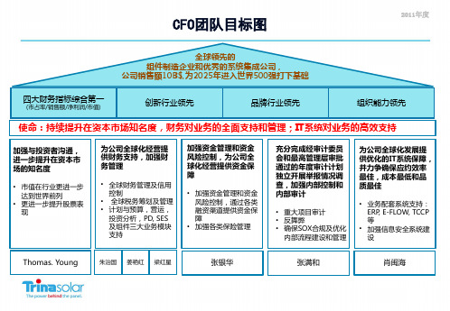
• 加强各类保险管理
充分完成经审计委员 会和最高管理层审批 通过的年度审计计划 独立开展举报情况调 查,加强内部控制和 内部审计
• 重大项目审计 • 反舞弊 • 确保SOX合规及优化
内部流程建设和管理
为公司全球化发展提 供优化的IT系统保障, 并力争确保应约效率 最佳,成本最低和品 质最佳
• 建立完善的全球保险管 理制度和体系
• 提升现金流预测能力 • 完善资金部管理架构
• 完善和健全常州公司内部财务 会计制度及流程
• 提高财务基础管理工作服务质 量,为相关部门提供基础财务 数据的信息支持。
• 建立和完善全球信用管理体系 (上、中、下游价值生产链、 包括制度、流程、组织和信用 系统等);
• 负责日常的客户和供应商的信 用审批、合同评审、提供信用 风险防范建议和信用风险的及 时预警反应;
研发技术决策和支持
制造决策和支持
下游业务决策和支持
部门使命:持续推进和改善全面预算管理,财务对业务的全面支持和管理,实现持续的开源节流
加强与业务部 门沟通,完善和 提高全面预算 管理体系
• AOP的编制 与管理
• 财务计划与 预测
• 预算分析与 绩效
为公司提供投 资分析,建立投 资分析管理体 系
• 资本性支出 立项管理
exemption ruling • Changzhou APA
• PD; Tax analyst & tax manual updates • SES; tax incentive investigation • R&D; enjoy high tech 15% CIT • Supply chain ;China VAT refund & EU VAT
卡梅伦液压数据手册(第 20 版)说明书

iv
⌂
CONTENTS OF SECTION 1
☰ Hydraulics
⌂ Cameron Hydraulic Data ☰
Introduction. . . . . . . . . . . . . ................................................................ 1-3 Liquids. . . . . . . . . . . . . . . . . . . ...................................... .......................... 1-3
4
Viscosity etc.
Steam data....................................................................................................................................................................................... 6
1 Liquid Flow.............................................................................. 1-4
Viscosity. . . . . . . . . . . . . . . . . ...................................... .......................... 1-5 Pumping. . . . . . . . . . . . . . . . . ...................................... .......................... 1-6 Volume-System Head Calculations-Suction Head. ........................... 1-6, 1-7 Suction Lift-Total Discharge Head-Velocity Head............................. 1-7, 1-8 Total Sys. Head-Pump Head-Pressure-Spec. Gravity. ...................... 1-9, 1-10 Net Positive Suction Head. .......................................................... 1-11 NPSH-Suction Head-Life; Examples:....................... ............... 1-11 to 1-16 NPSH-Hydrocarbon Corrections.................................................... 1-16 NPSH-Reciprocating Pumps. ....................................................... 1-17 Acceleration Head-Reciprocating Pumps. ........................................ 1-18 Entrance Losses-Specific Speed. .................................................. 1-19 Specific Speed-Impeller. .................................... ........................ 1-19 Specific Speed-Suction...................................... ................. 1-20, 1-21 Submergence.. . . . . . . . . ....................................... ................. 1-21, 1-22 Intake Design-Vertical Wet Pit Pumps....................................... 1-22, 1-27 Work Performed in Pumping. ............................... ........................ 1-27 Temperature Rise. . . . . . . ...................................... ........................ 1-28 Characteristic Curves. . ...................................... ........................ 1-29 Affinity Laws-Stepping Curves. ..................................................... 1-30 System Curves.. . . . . . . . ....................................... ........................ 1-31 Parallel and Series Operation. .............................. ................. 1-32, 1-33 Water Hammer. . . . . . . . . . ...................................... ........................ 1-34 Reciprocating Pumps-Performance. ............................................... 1-35 Recip. Pumps-Pulsation Analysis & System Piping...................... 1-36 to 1-45 Pump Drivers-Speed Torque Curves. ....................................... 1-45, 1-46 Engine Drivers-Impeller Profiles. ................................................... 1-47 Hydraulic Institute Charts.................................... ............... 1-48 to 1-52 Bibliography.. . . . . . . . . . . . ...................................... ........................ 1-53
“分拆高手”李永伟:让资本成为互联网企业发展的加速器

“分拆高手”李永伟:让资本成为互联网企业发展的加速器作者:田晶来源:《中国商人》2020年第07期“加入普华永道就像做了一道选择题!”网易有道公司的新任财务副总裁李永伟说。
李永伟出生于1979年,从暨南大学工商管理硕士研究生毕业后,在普华永道会计事务所北京分所得到了自己的第一份工作。
对于很多财务人员而言,加入梦寐以求的普华永道,就意味着“开挂”的职业生涯拉开了序幕,李永伟提到普华永道时,却仿佛他高考中随手刷过的一道题一般轻松。
不过,此后被业界誉为“分拆高手”的李永伟,正是由普华永道展开其职业生涯里的系列经典战例和高光时刻。
对于那些需要在业务裂变的关键时期加速“抢钱”、“抢地盘”的独角兽们,李永伟这样的“分拆高手”,是红牛一般的高能饮料,不仅能给资本旷野中的苦行者们解渴,还令人上瘾。
2008年,全球金融危机爆发,企业募资压力急剧增加。
当时,李永伟正是普华永道负责搜狐公司旗下搜狐畅游的项目经理。
对于来势汹汹的资本寒流,他并未感到无助和绝望,依然有条不紊地进行着搜狐畅游美股上市的审计工作。
李永伟当时的淡定,是基于他本人的一个常识性的判断:从全球范围内来看,美国资本市场具有明确的规则和稳定的政策,属于机制最成熟、规模最大的市场,依旧吸引着国内大批企业赴美上市。
但他清楚地知道,在当时的背景条件下要成功执行一个美股IPO,打开美国资本市场的大门,并不是一件容易的事。
“搜狐畅游”要通过分拆的方式在美上市,最起码要满足三个基本条件。
首先,需要专业会计师事务所出具的审计报告;其次,要提供完整的上市招股书,并经过多次答辩和修改之后,获得SEC的同意;再次,要确认股票能够顺利卖出去。
这其中,出具审计报告和编写招股书是李永伟的重要任务,这是一份极具挑战性的工作,任何一项财务数据都要非常负责。
李永伟深知责任重大而勇于担当,在短时间内高质高效地完成了任务。
合格的审计报告,不仅促成搜狐畅游赴美IPO一举成功,为公司业务的增长和拓展奠定了财务基础,还进一步巩固了普华永道对互联网科技企业进行IPO审计的江湖地位。
cfop公式表范文

cfop公式表范文CFOP公式表是一种用于解决魔方的算法方法。
CFOP是指魔方的四个主要步骤:交叉(Cross),F2L(First Two Layers),OLL(Orientation of the Last Layer),PLL(Permutation of the Last Layer)。
本文将详细介绍CFOP的每个步骤的公式,以帮助小白更好地解决魔方。
1. 交叉(Cross):(1)白色棱块的交叉:RUR'U'RU2R'U'(2)黄色棱块的交叉:FRUR'U'F'(3)蓝色棱块的交叉:F'L'U'LUF(4)绿色棱块的交叉:F'R'U'RUF2. F2L(First Two Layers):角块和棱块是一组放在第一层的块,F2L是指先组装这两层。
(1)第一层角块:RUR'U'RU2R'(2)第一层棱块:URU'R'U'F'UF3. OLL(Orientation of the Last Layer):在第一层和第二层都完成后,我们需要调整最后一层角块的正确朝向。
(1)只有一个角块朝向正确:RU2R'U'RUR'(2)两个角块相邻朝向正确:FRUR'U'F'(3)两个角块对角朝向正确:RU2R2U'R2U'R2U2R(4)四个角块都朝向正确:RU2R'U'RU'R'4. PLL(Permutation of the Last Layer):在完成了第一层、第二层和第三层角块朝向后,我们需要调整最后一层角块的位置。
(1)形成十字的情况:RU2R'U'RU'R'(2)形成条的情况:FRUR'U'F'(3)角块位置不对应的情况:RUR'U'RU'R'(4)角块位置对应的情况:RU2R'U'RUR'此外,还有一些特殊情况下的公式,如:(1)两个角块位于对角位置的情况:RUR'U'RU'R'U2RU'R'(2)两个角块位于相邻位置的情况:RUR'U'RU'R'U'RUR'(3)F面有两个角块已经正确归位的情况:R'U'RU'RURURU'R'(4)F面有两个角块归位,但颜色反了的情况:RUR'URU2R'U2RU'R'U'RU'R'以上是CFOP公式表的部分内容,通过掌握这些公式,可以逐步提高魔方的还原速度和技巧。
圆筒式磁控溅射靶的磁场仿真与结构设计

第52卷第8期表面技术2023年8月SURFACE TECHNOLOGY·371·圆筒式磁控溅射靶的磁场仿真与结构设计王栋,蔡长龙,弥谦,王麟博,刘桦辰,侯杰(西安工业大学 兵器科学与技术学院,西安 710021)摘要:目的探究一种可用于实现圆柱形工件外表面镀膜设备的可能性,设计了一种新型的圆筒式磁控溅射靶结构,溅射在圆筒状靶材内表面发生,从整个圆周方向对工件外表面镀膜,以改善传统长管工件镀膜设备体积庞大、结构复杂的不足。
方法首先对圆筒式磁控溅射靶进行初始结构设计,再运用有限元分析软件COMSOL中静磁无电流仿真模块,通过控制变量法对溅射靶内部冷却背板厚度d1、内磁环轴向高度h1、内磁环径向宽度Δr1、外磁环轴向高度h2、外磁环径向宽度Δr2以及内外磁环间距d2不同结构参数下的靶面水平磁感应强度值进行仿真与研究。
在此基础上进行磁场优化并设计出溅射靶的理想磁铁结构参数。
结果计算结果表明,当冷却背板厚度为13 mm,外磁环内径为266 mm、外径为310 mm、厚度为20 mm,内磁环内径为270 mm、外径为310 mm、厚度为22 mm,内外磁环间距为50 mm时,距靶面上方3 mm处最大水平磁感应强度为40 mT,磁场分布均匀区域可达40%左右。
结论此外考虑溅射靶内部的水冷、密封以及绝缘结构,最终设计的圆筒式磁控溅射靶整体高384 mm,最大直径432 mm,结构紧凑可靠,为长管工件外表面金属薄膜的制备提出了一种新的磁控溅射靶结构。
关键词:磁控溅射靶;磁场仿真;有限元分析;优化;结构设计;圆筒式中图分类号:TG174.442 文献标识码:A 文章编号:1001-3660(2023)08-0371-09DOI:10.16490/ki.issn.1001-3660.2023.08.032Magnetic Field Simulation and Structure Design ofCylindrical Magnetron Sputtering TargetWANG Dong, CAI Chang-long, MI Qian, WANG Lin-bo, LIU Hua-chen, HOU Jie(College of Ordnance Science and Technology, Xi'an Technological University, Xi'an 710021, China)ABSTRACT: In order to explore the possibility of a device which can be used to coat the outer surface of cylindrical workpiece, a new type of cylindrical magnetron sputtering target is designed. Sputtering takes place on the inner surface of the cylindrical target, and the outer surface of the workpiece is coated from all sides to improve the large volume and complex structure of the traditional coating device for long tube workpiece. Firstly, the initial structure of the cylindrical magnetron sputtering target was designed, and then the magnetostatic non-current simulation module in the finite element analysis software收稿日期:2022-06-24;修订日期:2022-09-14Received:2022-06-24;Revised:2022-09-14基金项目:国家自然科学基金(11975177);西安市智能探视感知重点实验室资助项目(201805061ZD12CG45);西安市智能兵器重点实验室资助项目(2019220514SYS020CG042)Fund:National Natural Science Foundation of China (11975177); Xi'an Key Laboratory of Intelligent Visitation Perception (201805061ZD12CG45); Xi'an Key Laboratory of Intelligence (2019220514SYS020CG042)作者简介:王栋(1998—),男,硕士研究生。
等值图fly图形研究团队

02
等值图技术介绍
等值图定义
等值图是一种可视化技术,用于表示数据点在某个维度上的等值线或等值面。它 通过颜色、线条或符号的变化来表示数值的变化,帮助用户直观地理解数据的分 布和趋势。
等值图通常用于地理信息系统、气象预报、医学影像等领域,以展示空间数据的 连续变化。
非专业用户而言,理解Fly图形的含义和解 读数据的变化趋势也需要一定的学习和训练
。
04
等值图Fly图形研究进展
研究成果展示
01
成果1:等值图算法优化
02
等值图算法是图形渲染中的关键技术,该团队在算法优化 方面取得了重要突破,提高了渲染速度和图像质量。
03
成果2:实时图形渲染技术
04
团队成功研发出实时图形渲染技术,使得图形渲染更为流 畅,减少了延迟,提高了用户体验。
缺点
等值图对于数据的准确性和精度有一定要求,如果数据质量 不高,可能会影响可视化效果;对于大规模数据集,等值图 的计算和渲染可能比较耗时;此外,等值图的可视化效果也 受限于地图投影、比例尺等因素。
03
Fly图形技术介绍
Fly图形定义
总结词
Fly图形是一种基于等值线构建的 二维图形表示方法。
详细描述
Fly图形的优缺点
总结词
Fly图形具有直观、易于理解等优点,但也 存在计算量大、精度要求高等挑战。
详细描述
Fly图形能够清晰地表达数据的空间结构和 变化规律,使得数据可视化结果易于被用户 理解和接受。然而,由于其生成过程涉及大 量的计算和数据预处理,对于大规模和高精 度数据的处理存在一定的难度。此外,对于
TMS570的ECC逻辑自诊断机制与实现方法
TMS570的ECC逻辑自诊断机制与实现方法刘骋程;宗凯【摘要】A self-diagnosis procedure of ECC detection logic and protection mechanism targeting TMS570 is designed,which included RAM,Flash,FMC and FEE regions.By configuring the MCU internal registers,ECC error can be created intemionally.Then,the logic can be self-diagnosed.This approach is proved to be effective by online test and observation.This method can dramatically improve the validity and integrity of program and data,in addition,the safety of product can be guaranteed.%对TMS570的RAM ECC 校验逻辑、Flash ECC校验逻辑、FMC ECC校验逻辑和FEE ECC校验逻辑设计了自诊断流程并给出了详细实现方法,通过操作芯片内部寄存器来故意制造ECC错误进行逻辑自诊断.在多种型号芯片上进行了在线测试与观察,证明检测成功,能够有效地提高程序、数据的正确性和完整性,确保产品的安全性.【期刊名称】《单片机与嵌入式系统应用》【年(卷),期】2017(017)011【总页数】4页(P27-29,33)【关键词】MCU;TMS570;ECC;自诊断;安全关键系统【作者】刘骋程;宗凯【作者单位】南京康尼机电股份有限公司,南京210018;南京康尼机电股份有限公司,南京210018【正文语种】中文【中图分类】TP311.1安全关键系统(Safety Critical Systems,SCS)是指系统功能一旦失效将引起生命、财产的重大损失以及环境可能遭到严重破坏的系统。
旋翼跨音速非定常黏性绕流的高效CFD模拟方法
旋翼跨音速非定常黏性绕流的高效CFD模拟方法吴琪;招启军;林永峰;印智昭【摘要】为提高旋翼跨音速黏性绕流CFD模拟的效率,建立了一套基于隐式LU-SGS算法和OpenMP并行策略的旋翼非定常流场高效数值求解方法.首先,基于二维剖面翼型的Poisson方程求解和网格插值、翻折方法生成绕桨叶的O-C-O型贴体正交网格,并采用高效的“扰动衍射”(Disturbance diffraction method,DDM)挖洞方法、并行化"Inverse map"(IM)的贡献单元搜索方法,构建了旋翼运动嵌套网格系统.在此基础上,以耦合S-A湍流模型的非定常RANS方程为主控方程,对流通量采用高精度的Roe-MUSCL格式进行离散,时间推进采用隐式LU-SGS双时间方法,同时采用OpenMP并行策略加速旋翼流场求解.最后,运用所建立的方法分别对悬停ONERA 7A旋翼、前飞Caradonna-Tung(C-T)旋翼无升力状态及SA349/2旋翼有升力状态的气动特性及涡尾迹特征进行了模拟,通过与试验值对比验证了文中方法在旋翼非定常流场CFD模拟中的有效性和高效性.【期刊名称】《南京航空航天大学学报》【年(卷),期】2015(047)002【总页数】8页(P212-219)【关键词】旋翼;非定常气动特性;隐式算法;并行策略;S-A湍流模型;运动嵌套网格【作者】吴琪;招启军;林永峰;印智昭【作者单位】南京航空航天大学直升机旋翼动力学国家级重点实验室,南京,210016;南京航空航天大学直升机旋翼动力学国家级重点实验室,南京,210016;中国直升机设计研究所,景德镇,333001;南京航空航天大学直升机旋翼动力学国家级重点实验室,南京,210016【正文语种】中文【中图分类】V211.52直升机兼备垂直起降、空中悬停和高速前飞等独特优势,可以广泛用于运输、巡逻、救护等多个领域。
作为直升机的关键部件,旋翼提供了直升机飞行所需的升力、推进力以及操纵力,而旋翼往往工作在严重非对称的气流环境中:前飞状态下,前行桨叶易发生激波-附面层干扰现象,而后行桨叶易发生动态失速现象;旋翼在运动过程中,前一片桨叶拖出桨尖涡对后一片桨叶存在桨涡干扰现象(Blade vortex interaction, BVI);旋翼流场根部为低速/反向流动,尖部为跨音速流动。
- 1、下载文档前请自行甄别文档内容的完整性,平台不提供额外的编辑、内容补充、找答案等附加服务。
- 2、"仅部分预览"的文档,不可在线预览部分如存在完整性等问题,可反馈申请退款(可完整预览的文档不适用该条件!)。
- 3、如文档侵犯您的权益,请联系客服反馈,我们会尽快为您处理(人工客服工作时间:9:00-18:30)。
Lin Chen's CFOP (Algorithms)
First Two Layer (F2L)
First Two Layers, or F2L are normally the first two bottom layers of the 3x3x3 cube, or essentially all layers up until the last layer on larger cubes.
The definition is a little different depending on the subject or who you are talking to. Normally it is as above but it may also refer to the part of the Fridrich method that solves the pairs without counting the cross part.
Fridrich F2L
There are many ways to solve the 'F2L' on a cube. A common system is using the Fridrich method first two layer approach. After solving the cross, a corner-edge pair is paired up, and then inserted into the correct slot. A total of four corner edge (or 'CE') pairs are made and inserted to solve the first two layers.
The con cept of pairing up four corner/edge pairs was first proposed by René Schoof in 1981.
Algorithms:
Permutation of the Last Layer
PLL is the Permutation of the Last Layer, the last step of many speedsolving methods. In this step, the pieces on the top layer have already been oriented (OLL) so that the top face has all the same color, and they can now be moved into their solved positions. There are 21 PLLs (13 if you count mirrors and inverses as being the same) and each one is named after a letter. The following page gives a list of all of the PLLs, along with a picture and a list of common algorithms for each one. The diagrams below are top views of where you want the pieces to go. For example, the T Permutation (or 'T perm') swaps the UL and UR edges, as well as the UFR and UBR corners. Make sure to try out all of the available algorithms for a case to see which one feels the fastest to you - the same algorithm may not be the fastest for everyone, and shorter algorithms are not always faster than longer ones.
Algorithms:
Orientation of the Last Layer
OLL (short for Orientation of the Last Layer) is a last-layer step for 3x3 that orients all last-layer corners and edges in one step. It is the first last-layer step in many speedsolving methods, including the Fridrich Method. OLL is usually followed by PLL.
There are 57 kinds of algorithm for OLL. But you might be skipped this step if you are lucky enough
Algorithms:
The meaning of Alphabet
R=Right
L=Left
U=Up
D=Down
F=Front
B=Back。
