爱乐优机器人说明书
JMV Robotique FF130 Flap Folder 操作与维护手册说明书

COMPLETE SOLUTIONS FOR ON-DEMAND CD & DVD PRODUCTIONThank you for purchasing a JMV RobotiqueFF130 Flap FolderOPERATING & MAINTENANCE MANUALDocument Reference No. M/000116Production StandardT.ZZ 003 032JMV RobotiqueZI du Clos Aux Pois6/8 Rue de la CloserieLISSES91048 EVRY CedexFranceTel: 33 (0) 1 60 86 15 25Fax: 33 (0) 1 60 86 10 74Email:************************JMV Robotique reserves the right to amend or modify the specifications and design criteria applying to these products.WARRANTY TERMSThe FF130 is covered by the JMV Robotique standard warranty.WARRANTY EXCLUSIONSWe will not provide warranty repairs if, in our opinion, the problem resulted from externally caused damage, use outside the product’s specification, faults caused by inexperienced or non-approved repairers.The warranty does not cover the replacement of used consumables (or of parts which need periodic replacement during the life of the product as a result of the use made of them) unless the consumable itself is defective.IF YOUR PRODUCT FAILS WITHIN THE WARRANTY PERIOD•Prepare a description of the problem you have had•Make sure you have your proof of purchase document (invoice or receipt.)•Contact your supplierOPTIONAL EXTENDED WARRANTY PROGRAMMESOptional extended warranty programs are available. JMV Robotique extended warranty programs can only be purchased at the same time or shortly after the product to be covered has been purchased. Contact JMV Robotique for details.TABLE OF CONTENTSSection 1 SPECIFICATION 6Section 2 INTRODUCTION & INSTALLATION 72.1 Introduction 72.2 Installation 7 Section 3 SET-UP PROCEDURE 8 Section 5 OPERATION 9 Standard Terms & Conditions 10-13SECTION 1: SPECIFICATIONPower Supply: 110v to 240volts50Hz or 60HzSelf-adjustingCurrent (Typical) 100maFuse: 1 ampDimensions: Length 312 mm (12.3”) (excluding chutes)Width 195 mm (7.7”)Height 155 (6.1”)Weight 5.5 kg (12lbs) Throughput: 55 Sleeves per minute (minimum)SECTION 2: INTRODUCTION & INSTALLATION2.1 IntroductionThe FF130 Flap Folder has been designed to work in conjunction with the MEP120P CD Sleever and as such the unit is supplied complete with all the necessary fixtures, fittings and chute to convert the MEP120P.Note:As an aid to production, the FF130 will automatically separate out correctlysleeved CD’s and empty sleeves.2.2 Installation2.2.1 UnpackingYour FF130 has been fully tested at the factory and our Quality Control Department has ensured before despatch that it performs satisfactorily to the full specification.Should any damage have occurred in transit, please contact your shipperimmediately and also inform JMV Robotique.2.2.2 Power WiringThe power connection is made to the FF130 via the power cable supplied. Thepower circuit to the FF130 should be rated in accordance with the national and local electrical codes.The FF130 has been specially designed to accept power in the range 110v to 240v and either 50 or 60Hz.CAUTION: A good electrical ground must be connected to the FF130SECTION 3: SET-UP PROCEDURE3.1The Flap Folder is to be secured to a bracket which must be trapped underthe CD Sleever. In order to correctly trap the bracket the standard long feetfitted to the Sleever must be replaced with the shorter version supplied withthe Flap Folder. (Refer to your MEP120P manual for instructions on front andrear cover removal to gain access to the feet.)Having fitted the correct length feet, the mounting bracket (REP 200) must betrapped under the MEP120P with the two front feet located in the two holes inthe bracket.3.2The FF130 Flap Folder may now be hooked onto the bracket (200) byinserting the two screws protruding from the rear of the FF130 into the twoslots on the fold in the bracket.3.3The original collection hopper is now removed from the MEP120P andclipped on to the output of the FF130 i.e., The right hand end (When viewedfrom the front) using the screws supplied.3.4 The new chute ( 204) is now clipped into position at the output of theMEP120P using the two screws supplied.A container of some description should be placed beneath the FF130 tocatch ejected faulty sleeves which do not contain a CD.Connect the FF130 to the mains supply using the lead supplied.SECTION 4: OPERATIONThe Flap Folder when switched on via the switch adjacent to the power cable socket runs on a continuous basis, processing the sleeved CD’s as and when they aresupplied by the sleever.No adjustments are provided on the FF130 except for the correct positioning of the chute ( 204) and the collection hopper.STANDARD TERMS AND CONDITIONS OF SALEIn these conditions JMV Robotique has its registered office at ZI du Clos Aux Pois, 6/8 Rue de la Closerie, LISSES, 91048 EVRY Cedex, France. And the “Purchaser” is an individual or company with whom JMV Robotique contracts.All orders are accepted by JMV Robotique subject to Conditions of Sale set out below1. GENERALThese conditions shall prevail over any terms or conditions, which the Purchaser may seek or have sought to impose. Any conditions in the Purchaser’s Order will be binding only so far as they arecompatible with these Terms and Conditions and are expressly accepted by a Director of JMVRobotique in writing.2. ERRORSClerical errors may be corrected by JMV Robotique at any time.3. PRICESThe prices quoted are Ex Works and exclude Value Added Tax/sales tax. Any published list priceshall be subject to revision without notice according to JMV Robotique prices ruling at the time ofdelivery.4. SETTLEMENT TERMSPunctual payment is the essence of the Contract and the Purchaser will pay interest at the rate of 2% per month or part thereof of any overdue payments. Provided that the Purchaser has producedreferences which are in JMV Robotique’ opinion are satisfactory Settlement Terms will be net 30days from delivery. In all other cases payment shall be in advance upon submission by JMVRobotique of a pro forma invoice.5. DELIVERYAll times quoted for delivery are from receipt from the purchaser of a written order to proceed. Unless otherwise agreed in writing any quoted delivery date shall only be an estimate thereof and shall not be essence of the Contract. Whilst all reasonable endeavours will be made to comply with estimated delivery dates JMV Robotique does not accept any liability in respect of failure or delay in delivery.Where a Purchaser’s Order calls for a number of items JMV Robotique reserves the right to deliver all or any as soon as they are available at JMV Robotique’ premises and the Purchaser shall honour all statements presented in respect of such deliveries in accordance with the Settlement Terms.Notification to the Purchaser by JMV Robotique that the goods are available for delivery to anindependent carrier or to the Purchaser or his agent shall constitute delivery to the Purchaser. In all cases the carrier acts as Agent of the Purchaser.6. EXPORT CONTROLIf the goods or components thereof are licensed by the US Government for ultimate destination within the United Kingdom and any other EEC Country then the goods may not be re-exported without theapproval of JMV Robotique in writing.7. INSPECTION AND ACCEPTANCETHE PURCHASER MUST INSPECT THE PRODUCTS as soon as is reasonably practicable afterdelivery and shall within 3 working days of delivery give notice to JMV Robotique in detail of anydefect in the Products or of any other complaint which the Purchaser may have in relation to theProducts. Upon acceptance of the goods the Purchaser shall be deemed to acknowledge that thegoods so accepted conform in all respects with the specification of the goods ordered. If thePurchaser desires to inspect the goods prior to delivery such inspection must be made at JMVRobotique’ premises and notification of this requirement must be given in writing at the time of placing the order. If upon inspection the goods are approved by or on behalf of the Purchaser such approval shall constitute acceptance of the goods If no such inspection is made the Purchaser shall bedeemed to have accepted the goods when they are delivered to him or his agent or carrier unless thePurchaser gives written notice to the contrary to JMV Robotique within three working days ofdelivery. If the Purchaser fails to give such notice, the Products shall be conclusively presumed to be in all respects in accordance with the contract and free from any defect which would be apparent onreasonable examination and the Purchaser shall be deemed to have accepted the Productsaccordingly. The Purchaser acknowledges that JMV Robotique does not write software comprised inProducts sold by it and, accordingly, the Purchaser acknowledges that it is its sole responsibility tocheck (by the application of appropriate diagnostic software) for the presence of computer viruses insoftware comprised in Products before such Products are used or disposed of. In the event that thePurchaser establishes to JMV Robotique’ reasonable satisfaction that the Products are not inaccordance with the contract or are so defective, the Purchaser’s sole remedy in respect of suchnon-accordance or defects shall be limited as JMV Robotique may elect to the replacement of theProducts or refund of the purchase price or, where sums are owed by the Purchaser to JMVRobotique, the issue of a credit note against the return of the Products.THE PURCHASER MUST REFUSE PARCELS DELIVERED TO HIM IN A DAMAGED CONDITION.In no circumstances shall JMV Robotique be liable to compensate the Purchaser in damages orotherwise for non-delivery or late delivery of the Products or for any loss consequential or otherwisearising from non-delivery or late delivery.8. CANCELLATION OF ORDERIf at any time the Purchaser cancels an order for goods or services which JMV Robotique specifiesto be “non-standard”, i.e. not detailed on the current price list, JMV Robotique shall be entitled toclaim as damages an amount equal to 75% of the value of the order. For standard goods or servicesdamages would equate to 50% of the value of the order. These amounts the Purchaser agreesrepresents a genuine pre-estimate of JMV Robotique’ loss. Upon the cancellation of any order, JMVRobotique shall have the right to realize at its discretion after 60 days all monies, securities or goodspledged with or held by it on behalf of the Purchaser and to apply the proceeds in or towards thesatisfaction of such claim for damages and the Purchaser shall have no claim whatsoever againstJMV Robotique in connection therewith.9. PASSING OF PROPERTY AND RISKThe goods shall remain the sole and absolute property of JMV Robotique as legal and equitableowner until such times as the Purchaser shall have paid to JMV Robotique the agreed price. Fromdelivery of the goods the Purchaser acknowledges that he is in possession of the goods solely asbailee for JMV Robotique as shall as bailee insure and keep the same insured in the name of JMVRobotique in their full reinstatement value in some reputable insurance office and indemnify JMVRobotique for any uninsured loss thereof. For the purpose of recovering the goods JMV Robotiquemay enter any premises where the goods are stored or where they are reasonably thought to bestored and may repossess the same. Until such time as the purchaser becomes the owner of thegoods he will store them on his premises in a manner, which makes them readily identifiable as thegoods of JMV Robotique. The Purchaser is licensed by JMV Robotique to agree to sell JMVRobotique’ goods subject to the express conditions that the entire proceeds thereof are held in trustfor JMV Robotique and are not mingled with other monies or paid into any overdrawn Bank Accountand shall be at all times identifiable as JMV Robotique monies. The Purchaser is licensed to use thegoods in the manufacture of other goods provided that if the goods being the property of JMVRobotique are mixed with goods being the property of the Purchaser or are processed with orincorporated therein the product shall be deemed to be the sole and exclusive property of JMVRobotique.If the goods being the property of JMV Robotique are mixed with goods being the property of anyperson other than the Purchaser or incorporated therein the product thereof shall become or shall bedeemed to be owned in common with that other person in proportion to the value of the constituentparts therein. The Purchaser is licensed by JMV Robotique to agree to sell on the said productsubject to the express condition hereinbefore mentioned in relation to the proceeds of sale thereof.10. SPECIFICATIONAll drawings, specifications and particulars of the goods submitted are approximate only. Thedescriptions and illustrations contained in catalogues, price lists and other advertising of JMVRobotique are intended merely to present a general idea of the goods described therein and shall not form part of the Contract. Whilst every effort is made to ensure that the latest specification isavailable JMV Robotique reserves the right to incorporate new features and to supply products which may not be strictly in accordance with the specification agreed upon, provided that any changes inspecification shall not materially prejudice the performance of the goods.11. FORCE MAJEUREJMV Robotique shall not be liable for failure to perform or delay in performance of any contract or for the loss or damage to goods directly or indirectly caused by force majeure to include acts of God,fire, theft, riot, war, embargo, strike, shortage of labour, delays in delivery of material by suppliers,prohibition or export or import, confiscation or any other occurrence (whether or not of a similarnature to those specified) beyond the control of JMV Robotique. No consequences of any suchevent shall give rise to the recession of the Contract unless in the opinion of JMV Robotique thecontract becomes incapable of performance.12. WARRANTYa)JMV Robotique warrants that the goods will be of good quality and that JMV Robotique has title to sellthe same. JMV Robotique’ warranty of workmanship (if provided) shall be effective from the date on which the goods were accepted in accordance with Clause 8 and limited to 12 months from dispatch or such period as may be notified (“the warranty period”). During the warranty period JMV Robotique will replace, free of charge, any part or parts of the goods which fail to function as a result of faultscaused during their manufacture providing always that such faulty goods are returned carriage paid to JMV Robotique’ premises. The goods when repaired by JMV Robotique will then be returned carriage paid to the Purchaser. JMV Robotique shall not be liable under this warranty:i) where the defect results from the goods being subjected to abnormal usage or where the defectis due to the act, neglect or default of anyone other than JMV Robotiqueii) for the replacement or repair of the goods or part or parts thereof where such replacement, or repair becomes impossible as a result of force majeure or any other circumstances beyond JMVRobotique’ controliii) where the goods or any components or parts thereof are the subject of a separate guarantee given by a third party.iiv) where failure is caused by abuse or neglect.a)The Purchaser acknowledges that if he has not notified to JMV Robotique any particular purpose forwhich the goods are required all express or implied warranties or conditions statutory or otherwise as to quality of or fitness for any particular purpose of the goods are hereby expressly excluded and JMV Robotique shall not (except as set out above) be under any liability whatsoever in respect of defects in goods delivered or for any injury, damage or loss resulting from such defects from any causewhatsoever.13. LEGAL CONSTRUCTIONexcept where otherwise stipulated in writing the relations, arrangements and agreements between the parties shall be governed by the laws of England and all disputes which may arise under out of or in connection with any contract between JMV Robotique and the Purchaser shall besubmitted to arbitration by the London Court of Arbitration in accordance with its Rules for the timebeing in force. Service of any notices in the course of such arbitration to the address of thePurchaser given in the Contract shall be valid and sufficient. All references in the Terms andConditions to the masculine gender shall be deemed to include the feminine and neuter genders.Failure or neglect by JMV Robotique to enforce at any time any of the provisions hereof shall not be construed a waiver of JMV Robotique’ rights nor in any way affect the validity of the whole or part of this contract nor prejudice JMV Robotique’ rights to take subsequent action. The headings of theTerms and Conditions are inserted for convenience or reference only and are not intended to be part of or to affect the meaning or interpretation of any of the terms and conditions of this Contract. In the event that any of these terms, conditions or provisions shall be determined invalid, unlawful orunenforceable it shall be severed from the remaining terms, conditions and provisions that shallcontinue to be valid to the fullest extent permitted by law.14. STERLING PROTECTIONany quoted or listed sterling prices are subject to variation in the rate of exchange between sterling and the currency paid by JMV Robotique for whole or major components between the date of the contract and the time of the submission of JMV Robotique’ invoice to the Purchaser. JMVRobotique reserves the right to vary the price so that it accords with the said rate of exchangeprevailing at the time of JMV Robotique’ invoice.15. DEFAULTIf the Purchaser shall default in the performance of any of its obligations under the Contract JMVRobotique shall on giving the Purchaser notice in writing have the right without prejudice to any otherrights or remedies to take all or any of the following actions:a)cancel all or any part of any discount which might otherwise have been due under the terms ofthe contract;b)suspend any outstanding delivery of goods or parts thereof until such default shall have beenmade good;c)recover possession of that part of the goods to which the default relates and the Purchaser shallallow JMV Robotique free access to his premises to enable JMV Robotique to do so.No waiver or delay in exercise by JMV Robotique of its right under this clause shall be deemed to imply acceptance of the default or any subsequent default. If the Purchaser shall become bankrupt, go intoliquidation, have a Receiving Order made against him, or carry on his business under a Receiver JMVRobotique shall have the liberty without prejudice to any further remedies under the Contract to terminate the Contract forthwith by notice in writing to the Purchaser or Liquidator and recover possession of all equipmentfor which full payment of the contract price has not been received in c. above.。
焊接机器人说明书

焊接机器人说明书一、产品概述我们的焊接机器人是一款高效、精确且易于操作的自动化设备,专为工业制造过程中的焊接工作而设计。
通过先进的计算机视觉和深度学习技术,焊接机器人能够识别并跟踪焊接目标,实现高质量的焊接效果。
二、产品特点1、高精度:焊接机器人配备高精度的激光传感器和先进的运动控制系统,可以精确地跟踪和定位焊接目标,确保焊接质量的稳定性和一致性。
2、自动化:焊接机器人能够自动完成复杂的焊接流程,大大减少了人工干预和操作时间,提高了生产效率。
3、远程监控:通过无线网络连接,用户可以在远程监控焊接机器人的工作状态,随时了解焊接进程并进行调整。
4、易于操作:焊接机器人配备直观的用户界面,操作简单易懂,方便非专业人员快速上手。
三、使用步骤1、打开焊接机器人并启动:按下电源开关,等待机器人启动完成。
2、设置工作参数:根据实际需要,用户可以在控制面板上设置各种工作参数,如焊接速度、电弧长度等。
3、校准机器人:为确保焊接机器人的准确性,每次使用前需要进行校准。
用户应按照说明书的指示进行操作。
4、开始焊接:当所有参数设置完成后,用户可以按下开始按钮,机器人将自动进行焊接工作。
5、监控和调整:用户应时刻焊接进程,根据需要调整工作参数以确保焊接质量。
6、结束工作:当焊接完成后,用户应关闭机器人并清理工作现场。
四、注意事项1、请在安全环境下使用焊接机器人,避免在潮湿、高温或极寒环境中使用。
2、请确保机器人连接的电源稳定,防止电压波动导致设备损坏。
3、使用过程中如遇到问题,请立即停止使用,专业人员进行维修。
焊接机器人系统说明书一、概述本说明书旨在为使用焊接机器人系统的用户提供详细的操作指南和维护方法。
焊接机器人系统是一种高效、精确且可靠的自动化焊接设备,适用于各种工业制造领域的焊接工作。
通过本说明书,您将了解如何正确设置、操作和维护焊接机器人系统,以确保其正常运行并延长使用寿命。
二、设备组成焊接机器人系统主要由以下几部分组成:1、机器人本体:包括机械臂、关节、移动装置等。
机器人用户使用说明书

惠州市东扬科技有限公司前言非常感谢选购东扬科技BioROBO系列娱教型机器人!首先,我们先对机器人做个简单的了解!Robot—机器人,该词来源于1920年捷克的一个反映科幻内容的话剧。
剧中的一个人物名叫robota(捷克文,意为苦力,奴隶),一个形状像人的机器,可以听从人的命令做各种工作。
英文robot是从robota衍生而来的。
我国将robot 翻译为机器人,给人一种错觉,机器人一定具有类人的外形。
其实,应该为具有人的某种的功能的机器。
机器人到目前为止共经历了三个发展阶段:第一阶段:机器人只能根据事先编好的程序来工作,这时它就好像只有干活的手儿,不懂如何去处理外界的信息。
比如,这一阶段的机器人,让它去抓会损坏它的东西,只要你给了指令,它绝对会去抓,这种称为示教再显型。
此类型的机器人非常合适机器人教育,他能真正的让使用者了解和学习机器人的运动、控制原理。
第二阶段:机器人好像有了感觉神经,具有了视觉、感觉、听力等功能,使得它可以依据外界的不同信息做出相应的反馈。
如果再让它去抓某些东西,它就有可能不干啦。
这种称之为感觉型。
第三阶段:机器人就真正的长大成人了,这时它不仅具有多种技能,能够感知外面的世界,而且它还能不断的自我学习,用自己的思维来决策自己该干什么,该怎么去干。
这种称为知慧型,目前各国的科学家都在为这一梦想的实现而努力。
BioROBO系列机器人是由惠州市东扬科技与上海交通大学合作研制的娱教型机器人,BioROBO适用于教育、竞赛、娱乐等多领域,是机体可重构“智能”模块化机器人。
BioROBO娱教机器人有四种控制模式:(1)遥控模式:通过2.4G无线遥控器直接控制的模式,组合操纵杆,按钮,可步行,胳膊动作,练武及日常的精彩动作及表情表演。
(2)特设动作模式:按遥控器上的相应A或B键或AB组合键,即可表演一段完美的风情舞,可做多种趣味性的表演!(3)同步控制:通过BioROBO Studio虚拟机器人同步调试机器人动作。
AUBO-i5 用户手册说明书

AUBO - i5 USER MANUAL使用产品前请仔细阅读本手册AUBO Robotics用户手册AUBO-i5 & CB-MOriginal Version 4.5.11本手册适用于AUBORPE V 4.5,详见本手册版本信息章节,使用前请仔细核对实际产品版本信息,确保一致。
V4.5.11目录目录目录 (i)前言 ................................................................................................................................................ v ii 产品组成......................................................................................................................................... v ii 更多信息 (viii)1安全 (9)简介 (9)安全警示标志 (9)安全注意事项 (10)1.3.1概述 (10)1.3.2使用须知 (10)1.3.3人员安全 (12)责任及规范 (13)危险识别 (14)预定用途 (15)紧急情况处理 (15)1.7.1紧急停止装置 (15)1.7.2从紧急状态恢复 (16)1.7.3强制关节的紧急移动 (16)1.7.4机器人本体过大力安全保护 (17)1.7.5碰撞防护 (17)2搬运及注意事项 (19)3维护维修及废弃处置 (21)维护维修 (21)废弃处置 (22)4质量保证 (23)产品质量保证 (23)免责声明 (23)5机器人系统硬件组成 (25)6机器人安装 (27)简要安装步骤 (27)重要安全说明 (27)机器人工作空间 (28)6.3.1机器人机械尺寸 (28)6.3.2机器人运动范围 (29)安装机器人 (29)6.4.1底座 (29)6.4.2安装机器人本体 (30)安装末端工具 (32)6.5.1末端法兰机械结构尺寸 (32)电缆连接 (33)7I系列控制柜 (37)目录V4.5.11简介 (37)重要安全说明 (38)控制柜面板介绍 (39)7.3.1控制柜前面板 (39)7.3.2控制柜侧面板 (40)7.3.3控制柜上面板 (40)工作模式选择 (42)7.4.1手动模式 (42)7.4.2联动模式 (42)示教器使能开关 (46)8电气接口 (47)简介 (47)电气警告和小心事项 (47)控制柜通信接口 (48)控制柜I/O供电 (49)8.4.1内部电源供电 (49)8.4.2外部电源供电 (49)控制柜安全I/O (50)8.5.1简介 (50)8.5.2安全提示 (50)8.5.3安全I/O功能定义 (50)8.5.4默认安全配置 (52)8.5.5外部紧急停止输入 (52)8.5.6防护停止输入 (53)8.5.7缩减模式输入 (55)8.5.8防护重置输入 (56)8.5.9三态开关输入 (57)8.5.10操作模式输入 (58)8.5.11拖动示教使能输入 (59)8.5.12系统停止输入 (59)8.5.13系统紧急停止输出(常开) (60)8.5.14机器人运动输出 (61)8.5.15机器人未停止输出 (62)8.5.16缩减模式输出 (63)8.5.17非缩减模式输出 (64)8.5.18系统错误输出 (65)8.5.19外部紧急停止输出(常闭) (66)8.5.20上位机运行指示输出 (67)控制柜内部I/O (68)控制柜通用I/O (69)8.7.1通用数字I/O接口 (69)8.7.2模拟I/O接口 (72)8.7.3清除警报信号接口 (74)远程开关机控制I/O接口 (74)V4.5.11目录8.8.1远程开机 (75)8.8.2远程关机 (75)联动控制I/O接口 (75)机器人本体工具I/O接口 (76)9快速启动 (79)机器人基础功能介绍 (79)安装机器人系统 (79)机器人系统上电 (80)9.3.1上电前准备 (80)9.3.2系统上电 (80)机器人系统关机 (81)快速启动系统 (82)10示教器 (83)简介 (83)示教器操作界面 (84)10.2.1用户登录 (84)10.2.2初始界面 (85)10.2.3机器人移动控制 (85)机器人I/O设置及状态显示 (96)10.3.1控制器I/O (96)10.3.2用户I/O (97)10.3.3工具端I/O (98)机器人系统安装设置 (99)10.4.1初始位姿标定 (99)10.4.2工具标定 (100)10.4.3坐标系标定 (107)机械臂安全配置 (111)10.5.1基础配置 (111)10.5.2缩减模式 (112)10.5.3关节限制 (113)机器人系统设置 (114)10.6.1语言设置 (114)10.6.2日期时间设置 (114)10.6.3网络设置 (115)10.6.4密码设置 (115)10.6.5其他设置 (116)10.6.6更新 (116)扩展模块 (120)10.7.1Modbus插件 (121)系统信息 (123)关于 (124)10.9.1版本信息 (124)11在线编程 (125)简介 (125)目录V4.5.11功能模块说明 (127)11.2.1文本框编辑器 (127)工程管理 (127)11.3.1新建工程 (128)11.3.2保存工程 (129)11.3.3默认工程 (130)11.3.4加载工程 (131)11.3.5运行工程 (132)11.3.6工程根节点 (133)子工程(过程) (134)11.4.1新建过程文件 (135)11.4.2调用子工程命令(Procedure) (136)11.4.3调用指令组命令(Command Group) (137)移动命令(move) (139)11.5.1移动类型 (140)11.5.2路点命令(Waypoint) (146)11.5.3提前到达 (148)基础条件命令 (159)11.6.1循环命令(Loop) (159)11.6.2跳出循环命令(Break) (160)11.6.3结束单次循环命令(Continue) (160)11.6.4If命令(if...else). (161)11.6.5条件选择命令(Switch...Case...Default) (162)11.6.6设置命令(Set) (163)11.6.7等待命令(Wait) (164)11.6.8行注释命令(Line Comment) (165)11.6.9块注释命令(Block Comment) (165)11.6.10任务转移命令(Goto) (166)11.6.11弹窗命令(Message) (167)11.6.12空命令(Empty) (168)高级条件条件命令 (168)11.7.1多线程控制命令(Thread) (168)11.7.2脚本命令(Script) (169)11.7.3离线命令(Offline Record) (171)轨迹记录 (172)11.8.1调用轨迹记录命令(Record Track) (173)变量配置 (174)定时器 (175)11.10.1插入定时器(Timer) (175)11.10.2定时器状态显示 (175)仿真模型 (177)工程日志 (178)脚本文件 (179)附录 (I)V4.5.11目录术语 (I)认证与检测 (II)停止时间和停止距离............................................................................................................. I V 参照标准. (V)技术规格................................................................................................................................. V I 有效负载. (VII)机械臂安装要求.................................................................................................................. V III 报警信息及常规问题说明..................................................................................................... I X目录V4.5.11V4.5.11前言前言感谢您购买和使用本公司研发的轻型6自由度协作机器人AUBO-i5。
机器人操作说明书

机器人操作说明书斯图加特航空自动化(青岛)有限公司中国-山东-青岛-高新技术开发区Tel:0532- Fax:0532-1.概要 (3)2.坐标系 (7)3.程序创建 (11)4.动作指令 (12)5.焊接指令 (16)6.摆动指令 (18)7.寻点指令 (20)斯图加特航空自动化(青岛)有限公司中国-山东-青岛-高新技术开发区Tel:0532- Fax:0532-概要•机器人•控制装置•示教器机器人机器人是由通过伺服电机驱动的轴和手腕构成的机构部件。
手腕叫做机臂,手腕的接合部叫做轴杆或者关节。
最初的3轴(J1.J2.J3)叫做基本轴。
机器人的基本构成,由该基本轴分别由几个直动轴和旋转轴构成而确定。
机械手腕轴对安装在法兰盘上的末端执行器(焊枪)进行操控。
如进行扭转、上下摆动、左右摆动之类的动作。
机械臂控制装置机器人控制装置,由电源装置、用户接口电路、动作控制电路、存储电路、I/O电路等构成。
用户在进行控制装置的操作时,使用示教操作盘和操作箱。
动作控制电路通过主cpu印刷电路板,对用来操作包含附加轴在内的机器人的所有轴之伺服放大器进行控制。
- 3 -示教操作盘- 5 -与菜单相关的键控开关与JOG 相关的键控开关与执行相关的键控开关与编辑相关的键控开关2.坐标系坐标系是位确定机器人的位置和姿势而在机器人或空间上进行定义的位置坐标系统。
坐标系有关节坐标系、关节坐标系关节坐标系是设定在机器人的关节中的坐标系。
关节坐标系中的机器人的位置和状态,以各关节的底座侧的关节坐标系为基准而确定。
下图中的关节坐标系的关节值,处在所有轴都为0°的状态.关节坐标系刀具坐标系这是用来定义刀尖点(TCP)的位置和刀具姿势的坐标系.刀具坐标系必须事先进行设定.位定义时.将由机械接口坐标系代替刀具坐标系。
世界坐标系世界坐标系,是被固定在空间上的标准笛卡尔坐标系,其被固定在机器人事先确定的位置。
用户坐标系基于该坐标系而设定。
爱乐优说明书
以win7为例:一、右键桌面上的“计算机”,选“属性”选项注:xp系统为“我的计算机”二、点“更改设置”,再点“更改”,重命名计算机注:xp系统下为先选择“计算机名”选项三、按部门-姓名,拼音简称方式修改电脑用户名如“技术-黄庆坤”简写为“js-hqk”四、点确定,如果提示重启电脑,备份当前工作后重启电脑。
篇二:爱乐优简介爱乐优小优名片小优机器人又名爱乐优机器人,产品定位于0-12岁婴幼童的智慧启蒙,是机器人行业标志性产品之一,目前由聪锐机器人等国内几家机器人公司负责代理销售。
了解小优小优机器人是一个具有生命特征的智能机器人,可以成为您温馨家庭的一名小成员。
它上知天文下知地理,什么语文、数学、英语、科学、音乐、美术,全不在话下。
孩子在家就可以轻松学习,有的家长开玩笑说,以后就不用送孩子去幼儿园了。
基本特性环境感知、自主导航和避障声控对话,语音识别和交互面部表情和情绪特征wifi无线上网人工智能个性化定制幼教陪护,智能启蒙和开发产品亮点一、全球首款进入家庭的心智发育型亲子机器人二、第一款消费者买的起家庭智能机器人三、国家十一26颗高性能处理芯片8个智能传感器600多个高精度零部件6个高速微电脑芯片4个精密步进驱动马达3个srs高品质音响20000种会话内容——针对各种生活场景的互动会话 6500句声控文件——让小优具备听懂人类语言的能力 800个英语命令——贴身的中英文双语启蒙老师32个主题智能训练——涵盖宝宝成长过程中的方方面面小优档案中文名:爱乐优(简称小优)name:ilu 生日:2010年5月9日国籍:中国籍贯:北京星座:金牛座专长:陪宝宝玩,给宝宝当榜样,解答宝宝的疑问爱好:唱歌,帮助别人,看电影喜欢的颜色:绿色最爱吃的东西:机器人能量块最大优点:聪明、乐观、上进最喜欢的电影:《猫和老鼠》、《变形金刚》最喜爱的衣着:圣斗士黄金盔甲最爱的运动:跳舞最想去的地方:外太空最喜欢的事:陪宝宝聊天最大心愿:走遍全世界,带给每个孩子一个快乐的童年最大梦想:去火星旅行,找个火星机器人做女朋友最喜欢听到的话:爱乐优,i love you!座右铭:快乐至上!小优智能十大超凡智能一,音乐艺术培养。
ALTO 560 B 机器人操作手册说明书

Operator'sManualModel560 BForm No. 999836 3/99Clarke Technology Printed in the U.S.A.Table of ContentsOperator Safety Instructions (3)How To Prepare The Machine For Operation (4)How To Assemble the Handle (4)How To Install the Dust Bag (4)How To Install the Paper Filter Bag (5)How To Start the Machine (5)How To Change the Brush Segments (5)Instructions for Connection to the Power Supply and the Electrical Ground (6)Maintenance (7)Assembly Drawing (8)Parts List (9)Page -2- Clarke Technology Operator's Manual Model 560 BClarke Technology Operator's Manual Model 560 BPage -3-OPERATOR SAFETY INSTRUCTIONSWARNINGAVERTISSEMENTADVERTENCIADANGER:WARNING:DANGER:Failure to read the Owner's Manual prior to operating or attempting any service or maintenance procedure to your ALTO machine could result in injury to you or to other personnel; damage to the machine or to other property could occur as well.You must have training in the operation of this machine before using it. If your operator(s) cannot read English, have this manual explained fully before attempting to operate this machine.DANGER:Operating a machine that is not completely or fully assembled could result in injury or property damage. Do not operate this machine until it is completely assembled.Inspect the machine carefully before operation.DANGER:Machines can cause a fire when operated near flammable materials and vapors.Do not use this machine with or in areas near flammable fluids, fuels, grain dust,solvents, thinners, vapors or other flammable materials. This machine is not suitable for picking up hazardous dust.WARNING:To prevent electrical shock, always remove the electrical plug from the electrical outlet before doing any repairs or maintenance to this machine.WARNING:To prevent injury, always remove the electrical plug from the electrical outlet before changing the brush or accessories and before leaving the machine.WARNING:Maintenance and repairs performed by unauthorized personnel could result in damage or injury. Maintenance and repairs must be performed by authorized Clarke Technology personnel only.WARNING:Any alterations or modifications of this machine could result in damage to the machine or injury to the operator or other bystanders. Alterations or modifications not authorized by the manufacturer voids any and all warranties and liabilities.WARNING:To prevent electrical shock, do not use this machine on wet surfaces. Electrical compo-nents of this machine can "short-out" if exposed to water or moisture. Keep the electri-cal components of the machine dry. Protect the machine from rain. For storage, keep the machine in a dry building. Always clean the machine with a clean dry cloth.WARNING:To prevent damage to the power cord, do not let the brush touch the power cord when the machine is running. Always lift the cord over the machine.WARNING:Operating a machine without observing all labels and instructional information could result in injury or damage. Read all machine labels before attempting to operate. Make sure all of the labels and instructional information are attached or fastened to the ma-chine. Get replacement labels and decals from your distributor.CAUTION:Use of this machine to move other objects or to climb on could result in injury or dam-age. Do not use this machine as a step or furniture. Do not ride on this machine.Figure 1Figure 21122Figure 3Figure 4Page -4- Clarke Technology Operator's Manual Model 560 BClarke Technology Operator's Manual Model 560 BPage -5-3.Slide the clamp over the folded edge of the dustbag. Make sure the paper bag is included (see figure 6.)To start the machine, do the following:1.Step on the release lever.2.Lower the handle (see figure 7.)When the brush bristles become worn, replace the brush segments. To change the brush segments,follow this procedure:1.Turn the levers (figure 8, #1), that hold the plate, tothe left.2.Remove the nozzle plate (figure 8, #2).3.Remove the brush roller (figure 8, #3).4.Remove the four screws from each half (figure 8,#4).5.Install the new brush sections.Figure 5Figure 6Figure 7Figure 8112443Page -6-Clarke Technology Operator's Manual Model 560 BFigure 9(C). This adapter must be connected as shown in Figure 9(B) to an electrical ground in the electrical outlet. Make sure you use a plate screw and the ground tab to fasten the adapter.WARNING:Always use this machine with an AC three-conductor electrical system connected to the electri-cal ground. Replace any worn,cut or damaged cords. Replace any damaged plugs, receptacles or connector bodies.WARNING:For maximum protection against electric shock, use an electrical circuit interrupter. Get this device from your electrical supplier.WARNING:Do not cut, remove or break the ground terminal. Do not try to fit a three terminal plug into a receptacle or connector body that does not fit the plug. If the receptacle or connector body does not fit the plug, see your authorized dealer to get an authorized person to make the connection.WARNING:Do not move the machine over an electrical cord. Always lift the cord over the machine.EXTENSION CORDSUse only an approved extension cord with three conduc-tors, a plug with three terminals and a connector body with three holes. This machine has a power cord with wire size 18 AWG (AWG means American Wire Gauge).WARNING:If you use an extension cord,use an extension cord with minimum wire size 16 AWG.Figure 9Plate ScrewOutlet must be connected to the electrical ground(B)(A)Ground PinGround TabAdapter(C)NOTE: Do not use adapters shown in figures B and C in Canada.Figure 10How to Check the Commutator and the Carbon BrushesTo check the commutator and the carbon brushes, followthis procedure:1.Remove the screws that hold the motor cover andremove the cover.2.Remove the spring clips that hold the top of thevacuum motor and remove the top of the vacuummotor.3.Inspect the commutator. Take the machine to anauthorized repair location if you see any of the followingconditions.a.Small holes in the surface of the commutator.See figure 10A.b.Uneven color - Look for an even dark brown color.Clean areas or very dark areas indicate a problem.See figure 10B.c.High mica - The mica insulation must be lowerthan the commutator bars. See figure 10C.4.Remove the carbon brush assemblies and check thecarbon brushes. Replace both carbon brush assem-blies if either carbon brush is shorter that 1 cm (3/8inch). If either brush is shorter than 13 mm (1/2 inch),order replacement brushes. Be ready to replace bothcarbon brushes earlier than the normal inspectiontime.5.Install the top of the motor, the motor cover, and thefasteners.WARNING:The machine must be tested forelectrical safety after electricalrepairs are made.NOTE: For the best operation, have the machine checkedby an authorized repair person every 12 months. Forsafe operation and longer life of your machine, use onlygenuine Clarke Technology replacement parts.Circuit BreakerIn case of a motor overload due to a foreign object in theroller brush or impeller, the overload circuit breaker turnsoff the motor. After removal of the foreign object, the motorcan be restarted by pressing the button on the bottom of theunit.Clarke Technology Operator's Manual Model 560 B Page -7-CLARKE TECHNOLOGY Model 560BAssembly Drawing 3/995051Page -8- Clarke Technology Operator's Manual Model 560 BClarke Technology Operator's Manual Model 560 B Page -9-130037A Cover 1251600ABumper 13920688Nut, Plastic 1456205A Nut, M7 Left 1587608A Washer 1654711A Impeller 17964037Screw 4858546A Spacer1951910A Clamp, Strap 21052958A Chamber, Fan 11157878A Mount, Rubber 212961025Screw, Wing 213964007Screw, 6 x 12214980607Washer81554801A Housing, Blower 11658008A Screw, 4 x 8217980603Washer 218667201Retainer 11954304A Gasket 120912311Switch121964048Screw, 4 x 182********Insulation, Switch 12354802A Plate, Bottom 12454379A Gasket12556806A Plate, Sealing 12653010A Ring Retainer 127980933Washer 128961021Screw 12954302A Gasket130666612Nozzle Plate 131980935Washer Spring 232662004Lever233961027Shoulder Screw 23442217A Power Cord 135964006Screw, 3 x 16436912313Terminal Block 13754701A Insulation 13857318A Strain Relief 13957303A Rivet, Plastic 14058601A Spring 141924003Nut M614256808AFoot Pedal1Ref.No.Description Part No.Part No.Ref.No. No.Req’d. No.Req’d.Description 4356807A Foot Plate 14456810A Roll Pin14556809B Pivot, Handle 146961022Screw147668101Strain Relief 14844708B Motor14950295A Carbon Brush 250662005Clamp15153167A Insulating Disc 15258327A Shaft, Belt15351994A Circuit Breaker 15459905A Wheel 455660502Axle45651924A Clip, Locking 45752704A Cover, Hinged 158661507Cap, Brush End 159663602Thread, Guard 160902648Bearing26151406A Brush Segment 462964047Screw, 4 X 12863660905Brush Assembly 164663703Handle Grip165663906Handle Tube, Upp 166664506Cable Guide 167924004Nut M5268664507Cable Guide 169662104Bag Clip170964004Screw, 5 x 16271668310Spring172964062Screw, 8 x 25273662411Connector 174662412Connector 175662001Dustbag Clip 176660603Paper Filter Bag 177662801Elbow 178664102Hose179663909Handle Tube Low 180660609Cloth Filter Bag 181663409Gasket 182660201Adaptor 183903404Belt18454803AHousing Asm.1CAUTION:Repairs by qualified personnel only.ACHTUNG: Reparaturen nur durch Facharbeiter.PRECAUTION: Reparations par personnel specialize seulement.PRECAUTUION: Unicamente personal calificado deberian hacer reparaciones.CLARKE TECHNOLOGY Model 560BParts List 3/99NOTESALTO® PRODUCT SUPPORT BRANCHESALTO Danmark A/S, AalborgBlytaekkervej 2DK-9000 Aalborg+45 72 18 21 00ALTO Danmark A/S, HadsundIndustrikvarteretDK-9560 Hadsund+45 72 18 21 00ALTO Canada Ltd., Rexdale Ontario24 Constellation Ct.(416) 675-5830ALTO Overseas Inc., Sydney (Australia)1B/8 Resolution DriveCaringbah NSW 2229+61 2 9524 6122AL TO Cleaning Systems Asia Pte Ltd., SingaporeNo. 17 Link RoadSingapore 619034+65 268 1006ALTO Deutschland GmbH, Frondenberg (Germany)Ardeyer Str. 15D-58730 Frondenberg+49 2373 754 200AL TO Cleaning Systems (UK) Ltd., PenrithGilwilly Industrial EstatePenrithCumbria CA11 9BN+44 1768 868 995ALTO France S.A. StrasbourgB.P. 44, 4 Place d’OstwaldF-67036 StrasbourgCedex 2+33 3 8828 8400ALTO Nederland B.V. VianenStuartweg 4CNL-4131 NJ Vianen+31 347 324000ALTO Sverige AB, Molndal (Sweden)Aminogatan 18Box 4029S-431 04 Molndal+46 31 706 73 00ALTO Norge A/S, Oslo (Norway)Bjornerudveien 24N-1266+47 2275 1770CLARKE TECHNOLOGYAMERICAN SANDERS TECHNOLOGYA.L. COOK TECHNOLOGYCustomer Service Headquarters and Factory2100 Highway 265Springdale, Arkansas 72764(501) 750-1000Technical Service1-800-356-7274U. S. A. LocationsEuropean LocationsALTO U.S. Inc., St. Louis, Missouri16253 Swingley Ridge Road, Suite 200Chesterfield, Missouri 63017-1725ALTO U.S. Inc., Springdale, Arkansas2100 Highway 265Springdale, Arkansas 72764(501) 750-1000Customer Service - 1-800-253-0367Technical Service - 1-800-356-7274ALTO U.S. Inc., Bowling Green, Ohio 434021100 HaskinsALTO U.S. Inc., Clearwater, Florida 337651500 N. Belcher RoadALTO U.S. Inc., Carlstadt, New Jersey 07072150 Commerce Road(201) 460-4774ALTO U.S. Inc., Elk Grove, Illinois 600072280 Elmhurst Road(847) 956-7900ALTO U.S. Inc., Denver, Colorado 802041955 West 13th Ave.(303) 623-4367ALTO U.S. Inc., Houston, Texas 770407215 North Gessner RoadALTO U.S. Inc., Madison Heights, Michigan 48071-015829815 John R.(810) 544-6300ALTO U.S. Inc., Marietta, Georgia 300621355 West Oak Common Lane(770) 973-5225CLARKE TECHNOLOGY WARRANTYThis Clarke Technology Industrial/Commercial Floor Product is warranted to be free from defects in materials and workmanship under normal use and service for a period of one year from the date of purchase, when operated and maintained in accordance with Clarke T echnology's Maintenance and Operations instructions.This warranty is extended only to the original purchaser for use of the product. It does not cover normal wear parts such as electrical cable, rubber parts, hoses and motor brushes.If difficulty develops with the product, you should:(a).Contact the nearest authorized Clarke Technology repair location or contact the Clarke Technology Service Operations Department, 2100 Highway 265, Springdale, Arkansas 72764, for the nearest authorized Clarke T ech-nology repair location. Only these locations are authorized to make repairs to the product under this warranty.(b).Return the product to the nearest Clarke Technology repair location. T ransportation charges to and from the repair location must be prepaid by the purchaser.(c).Clarke Technology will repair the product and or replace any defective parts without charge within a reason-able time after receipt of the product.Clarke T echnology's liability under this warranty is limited to repair of the product and/or replacement of parts and is given to purchaser in lieu of all other remedies, including INCIDENT AL AND CONSEQUENTIAL DAM-AGES.THERE ARE NO EXPRESS WARRANTIES OTHER THAN THOSE SPECIFIED HEREIN. THERE ARE NO WARRANTIES WHICH EXTEND BEYOND THE DESCRIPTION OF THE FACE HEREOF. NO WARRANTIES, INCLUDING BUT NOT LIMITED TO WARRANTY OF MECHANT ABILITY, SHALL BE IMPLIED. A warranty registration card is provided with your Clarke T echnology product. Return the card to assist Clarke T echnology in providing the performance you expect from your new floor machine.ALTO, 2100 Highway 265, Springdale, Arkansas 72764.CLARKE TECHNOLOGY reserves the right to makechanges or improvements to its machine without notice.Always use genuine Clarke Technology Parts for repair.CLARKE TECHNOLOGY2100 Highway 265Springdale, Arkansas, 72764。
10K Lowrise LR10000 杠杆抬高机器人说明书
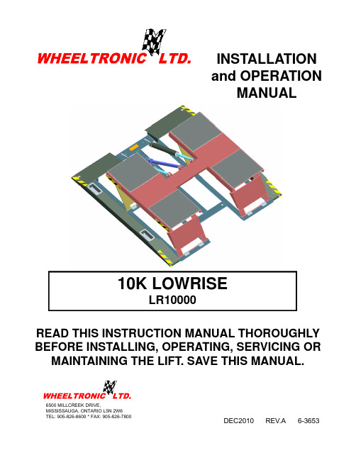
INSTALLATIONd OPERATIONand OPERATION MANUAL10K LOWRISE READ THIS INSTRUCTION MANUAL THOROUGHLY 10K LOWRISELR10000READ THIS INSTRUCTION MANUAL THOROUGHLY BEFORE INSTALLING, OPERATING, SERVICING OR MAINTAINING THE LIFT. SAVE THIS MANUAL.DEC2010 REV.A 6-36536500 MILLCREEK DRIVE,MISSISSAUGA, ONTARIO L5N 2W6TEL: 905-826-8600 * FAX: 905-826-7800TABLE OF CONTENTSTABLE OF CONTENTS (2)1.0 SAFETY AND OPERATING INSTRUCTIONS (3)2.0 SAFETY WARNING DECALS (6)3.0 GENERAL SPECIFICATIONS (8)Figure 1 - Overall Specifications (9)4.0 SHIPPING CONTENTS (10)5.0 TOOLS REQUIRED FOR INSTALLATION (10)6.0 INSTALLATION INSTRUCTIONS (11)6.1 BAY LAYOUT – SURFACE MOUNT (12)Figure 2 - Bay Layout – Surface Mount (12)6.2 UNPACKING THE LIFT (13)7.0 HYDRAULIC CONNECTIONS (13)7.1 ANCHORING PROCEDURES (13)Figure 3 - Anchoring Steps (14)8.0 BLEEDING PROCEDURE (15)8.1 FINAL CHECK OF ASSEMBLED LIST (15)8.2 OPERATION TEST WITH VEHICLE (16)9.0 LIFT OPERATION (16)Before Lifting: (16)Raising the Lift: (16)Lowering the Lift: (16)After Lowering: (17)10.0 RECOMMENDED MAINTANANCE (17)Inspect Regularly for: (17)10.1 MAINTANANCE SCHEDULE (17)11.0 TROUBLE SHOOTING (18)12.0 LIFT ASSEMBLY (19)12.1 LIFT PARTS LIST (19)13.0 POWER PACK ASSEMBLY (20)13.1 POWER PACK PARTS LIST (20)14.0 AVAILABLE ACCESSORIES (22)Figure 4 – Square Rubber Pad, Part No. 6-2776 (Set of 4) (22)Figure 5 – Pump Stand Assembly, Part No. 22573 (22)Figure 6 – Pump Stand Bolt Down 84”, Part No. 3-1027 (23)1.0 SAFETY AND OPERATING INSTRUCTIONS IMPORTANT SAFETY INSTRUCTIONSWhen using your garage equipment , basic safety precautions should always be followed, including the following:1. Read all instructions2. Care must be taken as burns can occur from touching hot parts3. Do not operate equipment with a damaged cord or if the equipment has beendropped or damaged – until it has been examined by a qualified person.4. Do not let a cord hang over the edge of the table, bench , or counter or come incontact with hot manifolds or moving fan blades.5. If an extension cord is necessary, a cord with a current rating equal to or morethan that of the equipment should be used. Cord rated for less current that theequipment may pverheat. Care should be taken to arrange the cord so that it will not be tripped over or pulled.6. Always unplug equipment from electrical outlet when not in use. Never use thecord to pull the plug from the outlet. Grasp plug and pull to disconnect.7. Let the equipment cool completely before putting away. Loop cord loosely aroundequipment when storing.8. To reduce the risk of fire, do not operate equipment in the vicinity of opencontainers of flammable liquids ( gasoline).9. Adequate ventilation should be provided when working on operating internalcombustion engines.10. K eep hair, loose clothing , fingers, and all parts of body away from moving parts.11. T o reduce the risk of electric shock, do not ise on wet surfaces or expose to rain.12. U se only as described in this manual. Use only manufacturer’s recommendedattachments.13. A LWAYS WEAR SAFETY GLASSES. Everyday eye glasses only have impactresistant lenses, they are not safety glasses.SAVE THESE INSTRUCTIONSWhen using this lift, basic safety precautions should always be followed, including the following:1. Thoroughly read all instructions in this manual and on the lift before installing,operating, servicing or maintaining the lift.2. Inspect the lift daily. Do not operate lift if it malfunctions or if problems have beenencountered.3. Never attempt to overload the lift. The manufacturer’s rated capacity is shown onthe identification label. Do not override the operating controls or the warranty will be void.4. Only trained and authorized personnel should operate the lift. Do not allowcustomers or bystanders to operate the lift or be in the lift area.5. Caution! Never work under the lift unless the mechanical safety locks areengaged.6. Always keep the lift area free of obstruction and debris. Grease and oil spillsshould always be cleaned up immediately.7. Never lift a vehicle with passengers inside.8. Before lowering the lift check the area for any obstructions.9. To protect against risk of fire, do not operate lift in the vicinity of open containersof flammable liquids.10. Adequate ventilation should be provided when working on internal combustionengines.11. Do not remove hydraulic fittings while under pressure.12. Only replace parts with genuine lift manufacturer supplied parts.SAVE THESE INSTRUCTIONSFor additional safety instructions regarding lifting, lift types, warning labels, preparing to lift, vehicle spotting, vehicle lifting, maintaining load stability, emergency stop procedures, vehicle lowering, lift limitations, lift maintenance, good shop practices, installation, operator training, and owner/employer responsibilities, please refer to “Lifting It Right” (ALI/SM) “Safety Tips” (ALI/ST) and vehicle lift points for service garage lifting SAE J2184.For additional instructions on general requirements for lift operation, please refer to “Automotive Lift-Safety Requirements For Operation, Inspection and Maintenance” (ANSI/ALI ALOIM).Installation shall be performed in accordance with ANSO/ALI ALIS, SafetyRequirements for Installation and Service of Automotive Lifts.ATTENTION! This lift is intended for indoor installation only. It is prohibited to install this product outdoors. Operating environment temperature range should be 41 – 104 °F (5 – 40 °C). Failure to adhere will result in desertification, loss of warranty, and possible damage to the equipment.2.0 SAFETY WARNING DECALSBe sure the operator is aware and understands all safety warning labels and followsthem accordingly.CAUTION TAPE LOCATIONSNOTE: CAUTION TAPE IDENTIFIES POSSIBLE TRIP HAZARDS WHEN THE LIFT IS LOWERED AND NOT IN USE. ENSURE THAT THIS TAPE IS REPLACED WHEN WORN ORREMOVED.3.0 GENERAL SPECIFICATIONSCapacity: 10000 lbs. 4536 kg Overall Width: 85” 2159 mm Overall Length: 83” 2108 mm Lowered Height: 3-7/8” 98 mm Raised Height: 21½” 546 mm Power Requirements:115 Volts AC, 1 Ph., 60 Hz.Figure 1 - Overall Specifications4.0 SHIPPING CONTENTSOverall Weight: 900lb / 408kg1 – Lifting frame assembly with cylinders attached1 – Pump box including:1 – Pumping unit assembly4 - 1/4” x 1 bolts with nuts & washers (Pump Mount)8 – ¾” x 5 ½” anchor bolts with nuts & washers (Frame Mount)1 – Tee fitting1 – Automotive lift safety tips1 – ALI manual “Lifting it Right”1 – Installation and Operation manual1 – Parts box including:4 – Height adapters4 – Height extensions2 – ¼”x29” hydraulic hose1 – 3/8” x 20’hydralic hose1 – Pumping unit mounting standMissing PartsIt is important to notify the delivery carrier immediately if any parts are damages or missing from shipment.5.0 TOOLS REQUIRED FOR INSTALLATION•16ft. Measuring Tape• Chalk Line•Rotary Hammer Drill•3/4” diameter Masonry Drill Bit• Hammer•SAE Wrenches and Ratchet Set• 2ft. Level• 4ft. Level• Crow Bar•12ft. Step Ladder• Side Cutters• Screwdrivers•4” x 4” Wooden Blocks (for unpacking)6.0 INSTALLATION INSTRUCTIONSWhen the lift arrives on site, please read the owner’s manual completely and make sure the installation instructions are fully understood. Check the contents of the hardware and accessory boxes to make sure no parts are missing and no freight damages exist before starting installation. Gather all the tools listed above and make sure the installation instructions are fully understood before commencing with the installation. IMPORTANT:It is the user’s responsibility to provide a satisfactory installation area for the lift. Lifts should only be installed on level concrete floors with a minimum thickness of five 4 1/4” or 115 mm. Concrete must have a steel reinforcing with a minimum strength of 3000 psi or 21 MPa and should be aged thirty (30) days prior to installation. Maximum slope must not exceed 1/16” per foot.Always pay special attention to the condition of the concrete such as age, cracking, chipping, and levelness. Please consult the architect, contractor or engineer if doubt exists as to the strength and feasibility of the floor to enable proper lift installation and operation.It is the user’s responsibility to provide all wiring for electrical hook-up prior to installation and to insure that the electrical installation conforms to local building codes. Where required, it is the user’s responsibility to provide an electrical isolation switch located in close proximity to the lift that will enable emergency stop capability and isolate electrical power from the lift for any servicing requirements.6.1 BAY LAYOUT – SURFACE MOUNTFigure 2 - Bay Layout – Surface MountNOTE: LAYOUT SHOWN WITH OPTION LINE COVER KIT EAK0299T13A6.2 UNPACKING THE LIFTRemove the metal strapping from the main structure package and slide the liftshipping skid. Open the accessory box and check the contents of the box.1. Position unit on a flat floor allowing a minimum of 6 feet from center of lift to sideobstructions and 12 feet from center of lift to front or rear obstructions. (Lift cylinder is on front end of lift.) Recommended overhead clearance is a minimum97 inches ceiling providing 25 inches for the maximum lift height and 6 feet forthe supported vehicle. For vehicles taller than 6 feet it is recommended that the user provides additional overhead clearance or a shut off mechanism to stop the lift from raising the vehicle too high.2. Remove pumping unit from box and install on pump stand.7.0 HYDRAULIC CONNECTIONSNOTE: When working with hydraulics it is important to keep all components clean.1. Select a position best suited for the power pack.2. Remove the breather filler cap and fill with 11 liters / 3 Gal. of ISO 32 10 weighthydraulic oil.3. Reinstall the breather filler cap onto the Power Unit.4. Connect the 90° elbow fitting (9/16” JIC-M, 3/8” JIC-M) with ‘O’ ring, to thehydraulic outlet port on the valve assembly of the power pack. The 90° elbow fitting is located in a hardware kit.5. Connect 11' (3353 mm) long hydraulic hose (female end) to the opposite end ofthe 90° elbow fitting.6. Locate the opposite (male) end of the 11' (3353 mm) long hydraulic hose.Connect to the central end of the swivel tee.7. Connect the male ends from both 29” long hydraulic hoses to the swivel tee sideends. Locate the opposite (female) ends of both 29” long hydraulic hoses and connect them to the inlet ports of the lift, which are located on the corresponding hydraulic cylinders.8. Tighten the hydraulic line in place so that it runs along the floor giving it a lowprofile.7.1 ANCHORING PROCEDURESNOTE: Check operation of lift (up/down) before anchoring the lift.1. Using a rotary hammer drill and a 3/4” concrete bit, drill through the floor at eachanchor bolt location. Make sure that the 3/4” concrete drill bit is in good condition.2. Clean out the drilling dust from the holes3. Assemble the nut and washer onto the supplied ¾” x 5 ½” long wedge anchorbolts. A minimum of six threads must be visible below the surface of the nut.4. Hammer in the anchors until they make contact with the base plate. Handtighten all anchor bolts. Remove any bolt assembly that does not grip concrete firmly and open expansion sleeve before reinstalling.5. Inspect to make certain lift sits firmly on floor. There should be no twisting orrocking motion in the base unit.6. Torque all anchor bolts to 75 ft-lbs.7. Position the power pack in the final desired location. Using a rotary hammer drilland a 1/4” concrete bit, drill four (4) holes and anchor the power pack stand to the floor using anchor bolts located in the hardware kit.8. Install the optional line covers to protect hydraulic hoses, refer to section 7.29. With all anchor bolts torqued as specified operate the lift checking its fulloperation.If anchor bolts do not tighten to 75 ft-lbs OR project more than 2 ¼” above the concrete surface, the concrete should be replaced by an appropriate concrete pad.(Consult Product Manufacturer / Supplier for further details.)Figure 3 - Anchoring Steps7.2 LINE COVER INSTALLATION (OPTIONAL)NOTE: FLOOR COVERS ARE DESIGNED TO SUPPORT FOOT TRAFFICAND TOOL BOXES UNDER 300LBS. ANY VEHICLE TRAFFIC WILL CAUSE DAMAGE TO THE LINE COVERS.1. Position the power pack in the location shown in the Bay layout Figure 22. Use the combination of straight (2-2736) and angled (2-2734 and 2-2733) linecovers provided in the options line cover kit EAK0299T13 to cover the hosesfrom the structure to the power pack. Any excess hydraulic hose should be coiled and zip tied to the power pack stand to avoid trip hazards.3. The angled line covers 2-2733 and 2-2734 will need to be cut at the cut lineshown in figure 2.4. Using a ¼” concrete drill bit, drill and fasten the line covers to the floor using the¼” x 1” long nail in anchors provided. The number beside the line coversrepresent the quantity of fasteners required to secure that side. Ensure that theline covers are sitting securely on the floor.NOTE: If the lift is shimmed to a point where the line covers do not sit flush due to interference with hoses, the line covers can be heated with a heat gun and then placed over the hoses for a cleaner look.8.0 BLEEDING PROCEDURE1. Press the up control button and raise the lift 10” (254mm) above the ground.2. Lower the lift to the ground and hold the down button until lift fully reaches theground.3. Repeat these steps 3-4 times to completely bleed the system of air. Check the liftfor hydraulic leaks at all connections.4. After bleeding, it is recommended that the filter assembly fitting (between thehydraulic hose and the power pack be cleaned. Place the fitting on a workbench and use an air gun to blow through the filter in the opposite direction to flow from the lift.8.1 FINAL CHECK OF ASSEMBLED LIFT1. Check for hydraulic leaks. ____2. Ensure all safety lock mechanisms are working correctly. ____3. Re-check level of decks. ____4. Check all fasteners, tighten if necessary. ____5. Operate lift to full stroke then lower to ground while checkingfor proper functionality. ____6. Ensure Customer Care Kit is complete and given to operator. ____a. Operation Manual____b. ANSI / ALI Lift It Right Manual ____c. ANSI / ALI Safety Tip CARD ____d. ANSI / ALI ALIS safety Requirements for Installationand Service of Automotive Lifts ____e. ANDI / ALI Quick Reference Guide ____7. Train end user on operation of the lift. ____8.2 OPERATION TEST WITH VEHICLE1. Lower lift to ground.2. Drive vehicle on to lift such that the lift’s contact frame is properly aligned with themanufacturer’s recommended lifting points for that vehicle.3. Raise lift to and lower onto first, second, and third lock positions during full rise toensure all locks are working correctly.4. Check lowering speed and smooth decent rate.5. Lower lift to ground and drive vehicle off lift.If any problems occur during the final checkout or operation of the lift please contact customer service at 1-800-268-7959.9.0 LIFT OPERATIONOperators of this lift should be trained by authorized personnel.Before Lifting:1. After making certain lift is in the fully lowered position, drive the vehicle into thebay and position it with the wheel in front of the superstructure.NOTE: The center of gravity of the vehicle should be centered on the liftingstructure. Refer to the "Lifting it Right" and "Vehicle lifting points quick referenceGuide" ALI/LP Guide provided. SAE J2184DO NOT TURN STEERING WHEEL WHILE TIRES ARE CROSSING2. Check to make certain car is fairly well centered left to right on lift.Raising the Lift:1. Hold toggle switch on pumping unit in “ON” position until locking leg drops ontoone of the three lifting height locking positions.2. Rock vehicle to check for stability.3. Lower the vehicle onto the mechanical locks.Lowering the Lift:1. After making certain lifting area is clear of people, electric cords, hoses, etc.,raise lift past next the safety lock to full height to disengage locking device.2. Press the lowering handle slowly until the lift is in its fully collapsed position..After Lowering:1. Drive car off lift without turning steering wheel while tires are crossing the lift.10.0 RECOMMENDED MAINTANANCEInspect Regularly for:a. Overload cracks in welds and metal fatigue.b. Misalignment of working parts.c. Hydraulic leaks.d. Low fluid level in pump reservoir. DO NOT use automatic transmission fluid.Use only petroleum based ISO 32-10 weight hydraulic oil.e. Lubricate all moving parts.f. Check locking latch for smooth and proper operation.10.1 MAINTANANCE SCHEDULEDaily:1. Check all hydraulic lines and fittings for pinch points , damage , cracks or leaks2. Check all electrical wiring for pinch points , cracks or damage3. Check all moving parts for uneven or excessive wear4. Repair or replace all damaged, defective, worn or broken componentsimmediately.5. Check the telescopic arms for movement. Clean any grease or oil from the liftingadapters.6. Raise and lower the lift at the beginning of each shift, without a vehicle on, toverify the lift is leveled and operating properly.7. Check the operation of the mechanical safety lock and release mechanism. If anydamage or malfunction is found, discontinue using the lift until repair isperformed.Weekly:1. Check and adjust hydraulic level.Every Two Months:1. Clean and re-grease hinge pins.Every Year:Inspect lift as per Automotive Lift Operation, Inspection and Maintenance(ALOIM).Every Two Years:Change hydraulic fluid.LUBRICATION:Where grease is required multi-purpose lithium grease.Where lubricating oil is required > multi-purpose SAE 30 lubricating oil.Where hydraulic oil is required > ISO 32 10W - non detergent hydraulic oil.11.0 TROUBLE SHOOTING1) Motor does not run:A. Breaker tripped or fuse blown.B. Motor thermal overload tripped. Wait for overload to cool.C. Defective control switch. Replace switch.D. Faulty wiring connections. Call electrician.2) Motor runs but the lift will not hold a load.A. A foreign object under check valve. Push handle down and push “raise”switch. Foreign matter should release under pressure.B. Remove check valve. Clean ball and seat and replace the nut.C. Oil level low, check oil reservoir. With lift cylinder (cylinders) in the downposition, pump reservoir should be full.3) Motor runs but the lift picks up partial load only.A. Lift is overloaded. Check capacity of lift and weight of vehicle.B. Relief valve setting is too low. Remove back hex cap on pump and adjustvalve clockwise.C. Hydraulic seals damaged (call customer service for instructions 1-800-266-7959)..4) Lift makes groaning sound when raising or lowering.A. Bleed cylinder manually.B. Add an ounce of oil to the air side of the piston.12.0 LIFT ASSEMBLYNOTE: Only replace parts with genuine lift manufacturers supplied parts12.1 LIFT PARTS LISTItem Part No. Description QTY.1 1-3368 3/8” x 19” x 22-1/2” Rubber Pad 42 2-2569HeightExtension Adapter 44”Height Extension Adapter 43 2-25704-1/2”4 6-1379 3/4” x 5-1/2” Anchor Bolt 45 1-3806 7/8” x 2-3/4” Piston Top Axle 26 2-2561 1/4” x 29” Hydraulic Hose M-F 2Assembly 2Cylinder7 3-10688 6-3516 F Pipe x F Pipe Swivel Tee 6-4-4 19 1-3374 Plastic Lug Nut Box 4restrictor 210 6-4018Flow11 1-3805 3/4” x 2-7/16” Pin 212 3-1066 Lock Leg Assembly 114 2-2566 11' High Pressure Hose 13-1026 Pump Stand Bolt Down Standard 1* Not shown in figure.13.0 POWER PACK ASSEMBLYNOTE: Only replace parts with genuine lift manufacturer’s supplied parts13.1 POWER PACK PARTS LISTAssembly No. Part No. Description1 6-2298 BOLT, 5/16” - 24” X 2-3/4” LG2 6-0774 COUPLING (4 POST POWER PACK)3 6-2157 PLUMBING PLUG 5/16” SAE4 6-2158 SEAL SHAFT 0.5X1X.25.338X.625X.065 6-2159WASHER6 62300 CORDSET 16/3 SJO 8FT 115V PLUG7 6-2156 WIRING ASSEMBLY AC 1PH FENNER8 6-2301 PACKAGE PLUG 9/16” SAE9 6-2157 PLUMBING PLUG 9/16 SAEMAGNET10 6-2162PLUMBING11 6-2302 ELECTRICAL STAKON NUT12 6-2164 SCREW TAPTITE TORX13 6-2165 COVER ASY SUCTIONINLETCLAMPHOSESEADJ.14 6-216615 6-2303 ELECTRIC CORD GRIP 3/4"NPT3/4"PIPENUTELECTRIC16 6-230417 6-1087 VALVE CARTRIDGE CHECK18 6-2305 VALVE LOAD DELAY19 6-2167 NUT 3/4”-16x1” HEX .2520 6-2168 WASHER 3/4” INT TOOTH21 6-1108 RELEASE HANDLE ASS’Y22 6-3782 END HEAD UNIV.23 6-2311 ELECT. REDUCER WASHER.35MMM6X124 6-2169SHCS,25 6-2170 WASHER 1/4 LC HI-COLLRMOTOR(2781-BC)115/230V,1PH,1HP26 6-2600RESERVOIRSCREW27 6-1091BREATHERFILLER28 6-137629 6-0884 INLET HOSE/FILTER ASS'Y30 6-1089 RELIEF VALVE CAP31 6-3783 TANK 2.0 GAL WHITE32 6-1846 CABLE TIE 8” LONG WHITERV1933 6-131934 6-2153 COMPRESSION TUBE NUT35 6-2154 COMP. TUBE SLEEVE36 6-3786 RETURN TUBE 1/2 OD 90 DEGO-RING37 6-0875RESERVOIR38 6-2306 PUMP ASS’Y 0.8 SHORT SPLINE.48X.063X.4239 6-2151SPRING40 6-0880 VALVE CARTRIGE RELEASE MANUAL41 6-2156 MICROSWITCH W/SNAP LID W-20042 6-2161 PLUMB. PLUG 3/8NPT43 6-3466 GROUNDING SCREW, #8-32 X 1/2"DECAL44 6-399614.0 AVAILABLE ACCESSORIESFigure 4 – Square Rubber Pad, Part No. 6-2776 (Set of 4)Figure 5 – Pump Stand Assembly, Part No. 22573Figure 6 – Pump Stand Bolt Down 84”, Part No. 3-1027EAK0299T13A Line Coverkit。
机器人焊接系统操作说明书

延锋座椅OTC机器人焊接系统操作说明一、操作步骤1、上工准备:a、上电;(顺序:变压器、焊接电源、机器人控制箱、系统主控箱)b、压缩气开启;c、检查焊丝、混合气是否充足,并确认气体流量;d、检查焊枪部位是否正常(导电嘴、喷嘴);e、检查机器人操作盘、示教器、系统主操作盒、副操作盒“紧急停止”打开,然后副操作盒处“运转准备”启动,打开外部轴伺服及读取外部轴位置数据f、检查夹具是否正常,并在水平位置,检查工件设定是否正确;g、按“机器人启动”第一次启动机器人伺服,成功后指示灯闪动,按第二次启动机器人自动模式,成功后指示灯亮,并确认其在起点在安全位置(区域干涉);h、三色灯只“绿”灯亮,系统准备就绪;i、工件准备,进入工作状态。
2、下班准备:a、机器人、夹具回到起点位置;b、断电;(顺序:系统主控箱、机器人控制箱、焊接电源、变压器)c、压缩气关闭,混合气关闭;d、现场飞溅清理。
3、运转条件:a、系统运转准备好,自动状态,触摸屏显示自动焊接画面;b、机器人自动模式,伺服启动且在安全位置;c、无报警信号(机器人报警,外部轴电机报警)d、三色灯只绿灯亮,自动焊接准备好e、三色灯红灯(报警或紧急停止),绿灯亮(准备好),绿灯闪(系统运转中),黄灯亮(待机状态,机器人未准备好),黄灯闪(机器人停止中);f、两主操作盒分别对应两个工位的启动、预约、再启动、预约指示及预约解除,运转中如有停止发生,预约启动会自动解除。
所有停止按钮功能相同4、触摸屏操作说明a、系统非常停止中检查机器人操作盘、示教器、系统主操作盒、副操作盒“紧急停止”是否可靠打开后,扣押副操作盒上“运转准备”按钮b、扣押“运转准备”启动主轴伺服电机,读取两工位外部轴位置数据,并且允许机器人操作,否则不能进行。
c、手动调整副操作盒手动/自动至手动位置“工位1正向”“工位1反向”控制工位1主轴旋转;“工位2正向”“工位2反向”控制工位2主轴旋转;上侧数值为主轴坐标点,单位为“度”,及显示主轴速度单位为“度/秒”“工位-1/工位-2”切换工位1及2,然后操作“+”“-”改变设定步号,一直操作“位置到达”指定工位到达设定位置,下方显示是否到达“定义位置”,上方显示目前的回转形式(说明:回转形式及步数及位置设定不在此屏幕设定)下侧为机器人周边调整,“1-门开”“1-门关”“2-门开”“2-门关”为点动操作两工位防护门,“1-护升”“1-护降”“2-护升”“2-护降”为两工位调整遮光板升降,“送丝”“退丝”“检气”“伺服启动”“自动输入”为方便机器人焊前操作,以上按钮为带灯显示按钮,到位后自动点亮指示灯。
AirSpace G6 - 机器人操作手册说明书

R E V 2 10122022USER MANUAL G6TABLE OF CONTENTSSafety PrecautionsTechnical DataMachine ComponentsOperating InstructionsQuick StartUser ScreensMachine Run ModesRecommended MaintenanceFactory Machine SettingsError CodesMaintenanceServiceAccessories2Safety Precautions•Always make sure the power is disconnected before touching any electrical part of the machine.•In case of an emergency, _______________•During the installation and set up, the machine should be off and the power should be disconnected.•Before doing any work on the machine, the machine should be turned off, disconnected and completely cooled down.3Technical Data4Machine ComponentsCKey:A: On/Off switchB: Connector for optional foot switch or photo eye C: USB ConnectorD: Main ScreenE: Clamp LeverF: NozzleG: Film RollerH: Guide RollerI: Power Cord Connector AD5E FG H BIAIRSPACE G6 -OperatorAir Pillow and Bubble on Demand Quick Start User Guide#8•The Main Screen will appear.•If top of screen is red, the machine is not running.•If the top of the screen is green, the machine is running.Toll Free in US: (800) 457-3961For assistance and questions contact Customer Service, 8 a.m. to 5 pm EST at (800) 457-3961. After hours, leave a message.#4•Thread the film around the inflationtube•To access the film channel opening,take the film and rub your fingers together to separateInflation tube#3•Rotate the clamp lever counterclockwise to releaseRotate clamp counter-clockwise#6•Rotate the clamp clockwise to lock down film#5•Pull the film throughRotate clamp clockwise#7•Plug the machine in and turn it on with the On/Off switch. Plug in optional accessories (photo eye or foot switch) as indicated.Main screen#1•Using a Philips screwdriver, position the roller in the back screw hole.•Place the film on the roll holder. •If you are using printed film, make sure the printed information is facing you; if you are NOT using printed film, make sure the channel is on the left. Plug for footswitch or photoeyeOn/Offswitch#2A•For air pillows , flip the roller stop so the blue tab is visibleRoller in the back screw holeBlue tabFil m#2B•For bubble film , flip the roller stop so the yellow tab is visibleYellow tabPress Red stop button to halt operation.Press Green start button to initiate operation.EZ AirQuick Start Supervisor GuideThread the film as indicated on the diagram.* (Makesure the information on the film is facing you.)Plug in the machine and turn it on and see the MAIN SCREEN. Press the AIRSPACE G6 logo.The PASSWORD screen will appear.On the PASSWORD SCREEN, Enter the code “2244”. The SETTINGS screen will appear.Main ScreenPassword ScreenThe SETTINGS SCREEN allows you to customize your job to meet your film characteristics and operational need. Press:•SPEED to select run speed.•FILM to indicate the specs of the film being used •MODE to select various run options•FINE TUNE to adjust to motor speed, fan speed and temperature•BACK to return to the Main ScreenSettings ScreenSPEED SCREEN : Choose the appropriate setting.Pillows on Demand (POD)Bubble on Demand (BOD)FAST 100’ per minute 40’ per minute NORMAL 70’ per minute 30’ per minute SLOW40’ per minute25’ per minute7Speed ScreenEZ AirQuick Start Supervisor Guide –Film SelectionFILM WIDTH SCREEN:Choose the appropriate film width:•PILLOW selects Pillow Film. •BUBBLE selects Bubble film.FILM TYPE SCREEN:If Pillow Width is selected: You will be prompted to select the Pillow Perforation Width.Film Width ScreenFilm Type ScreenFILM PERFORATION WIDTH: Choose the appropriate distance between perforations. (Pillow Film Only )After selecting film perforation distance, you will be prompted to select film thickness.Bubble Film PerforationWidth ScreenFILM THICKNESS SCREEN: Choose the appropriate film thickness.Once film settings are complete, you will be returned to the main screen. Press the Green Button to Start your job.For assistance and questions contact Customer Service, 8 a.m. to 5 pm EST at (800) 926-3700.After hours, leave a message.8After selecting film type, you will be brought to the Film Width Screen.PILLOW•8” Wide •10” Wide •12” WideBUBBLE•12” Wide •15” WideIf Bubble Width is selected: You will be prompted to selectthe Film Thickness.BUBBLEPILLOW8” WIDE PILLOW •4” Perforation •5” Perforation •8” Perforation •10” Perforation •12” Perforation10” WIDE PILLOW •4” Perforation •6” Perforation •8” Perforation •10” Perforation •14” Perforation12” WIDE PILLOW •4” Perforation •8” Perforation •12” PerforationFilm Thickness Screen•0.75 mil •0.80 mil • 1.00 mil • 1.20 mil •1.80 milMain Screen•Green button starts the machine•Red button stops the machine•Press the AIRSPACE G6 logo at thebottom of the screen to access themachine setting menusPassword Screen•Enter the Password 2244 to access thesetup menu•“Back” button takes you to the MainScreenSettings Screen•“Speed” button selects the run speed forthe machine•“Film” button selects the film being used•“Mode” button selects the operationmode for the machine•“Fine Tune” button accesses the settingsfor the selected speed and film type•“Back” button takes you to the MainScreen9SPEED SCREEN•“Fast” is a factory preset, which can be adjusted in the Fine Tune menu. •Pillow on Demand preset is 100’ per minute •Bubble on Demand preset is 40’ per minute•“Normal” is a factory preset, which can be adjusted in the Fine Tune menu. •Pillow on Demand preset is 70’ per minute •Bubble on Demand preset is 30’ per minute•“Slow” is a factory preset, which can be adjusted in the Fine Tune menu. •Pillow on Demand preset is 40’ per minute •Bubble on Demand preset is 25’per minute10FILM WIDTH SCREEN:Choose the appropriate film width:If Pillow Width is selected: You will be prompted to select the Pillow Perforation Width.Film Width ScreenPILLOW•8” Wide •10” Wide •12” WideBUBBLE•12” Wide •15” WideIf Bubble Width is selected: You will be prompted to selectthe Film Thickness.BUBBLEPILLOW•PILLOW selects Pillow Film.•BUBBLE selects Bubble film.FILM TYPE SCREENFilm Type ScreenAfter selecting film type, you will be brought to the Film Width Screen.Speed ScreenUser ScreensMODE SCREENNote: See mode descriptions section for more details about different modes •“Count” button selects the count run mode. When this button is pressed, you can select the number of air pillows you want to dispense in the count mode.•“Continuous ” button selects the continuous run mode •“Keypad” button selects the Keypad run mode•“Photoeye-Count” button selects the Photoeye triggered count run mode. When this button is pressed, you can select the number of air pillows you want to dispense in the count run mode.FILM THICKNESS SCREEN: Choose the appropriatefilm thickness.Film Thickness Screen•0.75 mil •0.80 mil • 1.00 mil • 1.20 mil •1.80 milFILM PERFORATION WIDTH: Choose the appropriate distance between perforations. (Pillow Film Only )Bubble Film PerforationWidth Screen8” WIDE PILLOW •4” Perforation •5” Perforation •8” Perforation •10” Perforation •12” Perforation10” WIDE PILLOW •4” Perforation •6” Perforation •8” Perforation •10” Perforation •14” Perforation12” WIDE PILLOW •4” Perforation •8” Perforation •12” PerforationMode ScreenUser ScreensFINE TUNE SCREEN•Press the number above “Motor Speed” to select the motor speed fine tune. Then adjust the number up ordown using the arrows.•Press the number above “Blower Speed” to select the fan speed fine tune. Then adjust the number up or down usingthe arrows.•Press the number above “Temperature” to select the seal temperature fine tune. Then adjust the number up ordown using the arrows.•“Enter” goes back to the Settings Menu•“Service” goes to a service screenSERVICE SCREEN•“Total Film Feet” is the linear feet of material the machine has dispensed•“Total On/Off Cycles” is the number of times the machine has started and stopped running•“Settings” navigates you to the photo-eye delay and accessories screen. Accessories gives the choice to use a photo-eye, or foot switch, Photo-eye delay let you fine tune the delay of the Photo-eye operation.•“Reset” changes the fine tune setting to the factory setting fora given speed and film choice•“Reset All” changes all the fine tune settings to the factory settings•“Back” goes back to the settings menuFine Tune ScreenService Screen Photo Eye Delay ScreenPHOTO EYE DELAY SCREEN•“Start Delay” is the delay of time to begin operating the machine after the photo-eye has been triggered to start.•“Stop Delay” is the delay of time to halt operation of the machine after the photo-eye has been triggered to stop.Continuous Run ModeHow to Enter the ModeSelect the “Continuous” button in the MODE menu and, if connected, disconnect the photo eye or the foot switch.How the Machine RunsWhen the green button on the main menu is pressed, the machine runs until the red button is pressed.Count Run ModeHow to Enter the ModeSelect the “Count” button in the modes menu and, if connected, disconnect the photo eye or the foot switchHow the Machine RunsWhen the green button on the main menu is pressed, the machine runs until either the red button is pressed, or the user-defined number of pillows have been dispensed from the machine.Keypad Run ModeHow to Enter the ModeSelect the “Keypad” button in the modes menu and, if connected, disconnect the photo eye or the foot switchHow the Machine RunsPress the number button to dispense that predetermined number of air pillows. For example, pressing the green “20” button dispenses 20 air pillows.Foot Switch Continuous Run ModeHow to Enter the ModeSelect the “Continuous” button in the modes menu and connect the foot switch to the back of the machine.How the Machine RunsWhen the foot switch is pressed, or the green button in the main menu is pressed, the machine runs until the foot switch or the red button is pressed.Photo Eye Continuous Run ModeHow to Enter the ModeSelect the “Continuous” button in the modes menu and connect the photo eye sensor to the back of the machine.How the Machine RunsWhen the green button in the main menu is pressed, the machine runs until the photo eye sees an air pillow. Then it pauses until the air pillow is removed. If the air pillow is removed, the machine runs again until the photo eye sees another air pillow. When the red button in the main menu is pressed, the machine is stopped.Foot Switch Count Run ModeHow to Enter the ModeSelect the “Count” button in the modes menu and connect the foot switch to the back of the machine.How the Machine RunsWhen the foot switch or the green button is pressed, the machine runs until either the foot switch is pressed, the red button is pressed, or the user-defined number of pillows have been dispensed from the machine.Temperature SettingsThese are factory settings preset into the machine. When a given speed and film thickness is chosen, a film seal temperature is automatically selected. These setting can be adjusted in the Fine Tune menu.Pillow FilmFilm Thickness0.75 mil0.8 mil 1 mil 1.2 mil 1.8 mil Fast260260275330340Normal256256260290300Slow240240252270286Bubble FilmFilm Thickness0.75 mil0.8 mil 1 mil 1.2 mil 1.8 mil Fast-288---Normal-284---Slow-272---Blower Speed SettingsThese are factory settings preset into the machine. When a given speed and film type is chosen, a film blower speed is automatically selected. These setting can be adjusted in the Fine Tune menu.Blower Speed %Film Width4"5"6"8"10"12"14"8"2333-334163-Fast10"25-405765-9112"28--65-95-8"1619-192432-Normal10"19-253543-5612"22--42-60-8"1417-9911-Slow10"15-111417-2412"19--17-25-Film Perforation WidthPillowBlower Speed %Film Width12"Fast12"19015"200Normal12"18015"200Slow12"17015"180Film PerforationWidthBubbleMaintenanceChanging Belts1.Turn off the machine and unplug thepower cord from the machine.2.Remove the two screws (A) holding onthe upper heater block cover3.Remove the two screws (B) holding onthe lower heater block cover.4.Remove the two covers from the machine.5.Raise the upper heater block by moving theclamp lever (C) into the up position.6.Pull the rear belt guide roller (D) forwardand pull off the old belts.7.Put the new belts on by putting the belt onthe front roller (E) first and then onto theback roller (D) with the roller pulledforward.8.Attach the upper lower side covers.A BCD EChanging the Blade1.Turn off the machine and unplug thepower cord from the machine.2.Remove the three screws (A) holding onthe left side of the housing.3.Remove the small screw (B) on themachine frame.4.Locate the blade between the circuit boardand blower hose, and remove the screw (C).5.Note the orientation of the blade beforeremoval, and make sure to align the newblade in the same manner that the oldblade was removed.6.When installing new blade, make sure frontof blade is seated below the outer surfaceof the nozzle. Failure to perform this mayresult in the film not cutting and cause clogs in the machine.7.Reinstall covers, and test machine function.ABCBlade removed from nozzleMaintenanceMaintenance Changing the Upper and Lower HeaterBlocks1.Turn off the machine and unplug the powercord from the machine.2.Remove the belts from the machine,following the maintenance guide forchanging belts. (Page 18)3.Remove two 5mm socket head screws onupper heater block (A) along with retainerplate.4.Pull out the upper heater block, carefully,until yellow wires are visible (B).5.Remove two 2mm socket head screws (C)from upper heater block, and remove wiresfrom terminals. The upper block is now freefor removal.6.Once the upper block is removed, the lowerblock can now be removed. To remove thelower block, simply lift from below the lowerblock until it is free from the locating posts.(D)7.Turn the lower block upside down to removethe 2mm socket head screws holding the redwires to the lower block. (E)8.The lower block is now free for removal.Installation for replacement heater blocks isthe reverse of removal.ABCDEMachine Error Codes Error Code SolutionCheck heater clamp is down all the way.•Check that the heater clamp is down •This error will clear when the clamp is in the down position.The film roll is not moving. This can be due to no film on the roller or in the feed rollers.•Check the roller has material on it.•Check the film is fed correctly onto the nozzle •Check the film is being pulled all the way through the heating element block and the feedrollers.The heating element is not heating. Please check wiring.•Check all wires going to the heating elements.•If no loose wire is seen, call Better Packages Service for assistance•Once the problem has been fixed, turn the machine off and then onOver temperature condition has been detected. Check temperature sensor and heater block.•Check for signs of over temperature, burnt belts, etc.•If signs of burnt belts are present, Call POLYAIR Customer Service for assistance.*•If no sign of burnt belt is present, replace Upper Heater Block.Temperature reading out of range. Check temperature sensor.•Replace Upper Heater Block.•Call POLYAIR Customer Service for assistance.*Motor rotation has been stopped. Check for film jam.•Check feed roller for a film jam.•If no film jam is seen, Call POLYAIR Customer Service for assistance.*Broken Belt or Belt Switch Activated•Replace both upper and lower belts.ServiceAccessories。
智能救援机器人的说明书

智能救援机器人的说明书一、引言智能救援机器人是一款高度智能化的设备,旨在应对紧急救援和灾害救援的需求。
本说明书将详细介绍智能救援机器人的功能、操作方式和注意事项等内容,以便用户正确并安全地使用该设备。
二、技术参数1. 外观尺寸:长 x 宽 x 高2. 重量:xxx 克3. 工作温度范围:-20℃至 50℃4. 动力系统:电池/充电器5. 通信方式:xxx6. 导航方式:xxx7. 最大行进速度:xxx 米/秒8. 工作时间:xxx 小时9. 防水等级:IP67三、功能介绍1. 搜索与救援智能救援机器人搭载先进的图像识别系统和传感器,能够准确地搜索被困人员,并快速定位其位置。
机器人还配备了携带器具,可用于紧急救援行动。
2. 监测与报警该机器人具备监测环境的能力,可通过传感器实时监测气体浓度、温度、湿度等参数。
一旦发现异常状况,智能救援机器人将迅速发出警报并提醒相关人员采取相应措施。
3. 语音交流与通信机器人配有高保真音箱和麦克风,可进行双向语音通信。
用户可以通过机器人发送语音指令或进行远程指挥,使救援行动更加高效和准确。
4. 物资携带与送达智能救援机器人拥有足够的载重能力,可以携带救援物资,如食品、药品、急救工具等。
它能够快速而安全地将这些物资送达给被困人员,提供急需的援助。
5. 自主避障与导航机器人采用激光雷达和红外传感器等技术,能够实现自主避障和规划最优路径。
即使在复杂的环境下,智能救援机器人也能够灵活应对,并顺利抵达目的地。
四、使用指南1. 起动与关机(详细说明如何启动和关闭机器人,包括电源按钮、充电方式等)2. 操作界面(详细介绍机器人的操作界面,包括触摸屏显示等)3. 故障排除(列举常见故障及解决方法,并提醒用户在遇到无法解决的故障时及时联系售后服务)4. 注意事项- 在使用机器人前,请仔细阅读本说明书并按照指引正确操作。
- 请避免将机器人暴露在高温或低温环境中,并避免机器人接触水分。
- 请勿在机器人的触摸屏上使用尖锐物品或过于剧烈地点击。
爱乐奇平板系列产品使用手册说明书

爱爱乐平板爱乐乐奇产板系列乐奇产品使列Ap 奇英语使用手pp语手册册1 概述2 智慧3 学习4 唱一5 注册6 添加7 切换8 会员9 购买10下述 ..........慧屋功能习任务功一唱功能册爱乐号加班级 ..换教材 ..员权限 ..买与充值下载 .....................能 ...........功能 .......能 ...........号 .....................................................值 .....................................................................................................................................................................目 录............................................................................................................................................................................................................................................................................................................................................................................................................................................................................................................................................................................................................................................................................................................................... 3 ... 4 ... 5 ... 6 ... 6 ... 9 11 12 13 131 概爱乐奇爱乐奇容,一脉绩,又将础。
六腿动物形机器人辅导者说明书

Six-Legged Animaloid Robot as a Trainer for Robotic CourseSiti Sendari a,1, Hakkun Elmunsyah a,2, Yogi Dwi Mahandi a,3a Electrical Engineering Department, State University of MalangJl. Semarang 5, Malang 65145, INDONESIA1*********************.id,2************.id,3************************Abstract–The innovation of robot technology attracts students to study and participate in many robot contests. Thus, robotic trainer is very urgent to be developed, especially an animaloid robot, which can encourage both of robotics course and robot contest. Here, the trainer was developed using seven steps of ten steps, i.e., (1) potential and problem, (2) data collection, (3) product design, (4) design validity, (5) design revision, (6) product trials, and (7) product revision. The developed trainer is a six-legged animaloid robot, which consists of five learning modules, i.e., (1) master-slave communication, (2) ultrasonic ranger, (3) motor servos, (4) flame sensors, and (5) extinguisher. The trainer was evaluated by media and material experts, where the validation results are 94% and 90%, respectively, while the validation result in the implementation stage is 87.31%. The result can be concluded that developed trainer is feasible and can be used as the learning media.Index Terms – six-legged animaloid robot, hexapod robot, robotic course, learning media1.IntroductionRobotic Innovation has been enhancing since1990, which starts as industrial tools and becoming as home appliances [11].This enhancement attracts students to studyrobotic course indicated by many of them attended competitions in the robotic field, such as IndonesianRobotics Competition held by The Directorate of HigherEducation.Robotics is one of compulsory courses at the Departmentof Electrical Engineering, State University of Malang (called as the TE-FTUM). The course provides mechanicaland electrical circuits, and the algorithms of movements. Arobotics lab is available to support the robotics course, where some trainers of line follower and arm robots aredeveloped. However, these modules are not enough to coverall competencies, especially for supporting robot contests. In order to support the competency of hardware and software troubleshooting, the “learning by doing” is a suitable method for teaching robotics [12]. Thus, trainers whichsupport the learning course and robotics competition areneeded. The trainers will be used as experiment tools, which could improve the knowledge of students.Robotics can be classified as (1) non-mobile robot, (2)mobile robot, (3) combination of non-mobile and mobile robots, and (4) extraordinary robot [10]. Here, humanoid and animaloid as extraordinary robots are needed to be developed at the TE-FTUM, while developing an animaloid robot is the main focus in this paper. Based on this reason, the six-legged animaloid robot, which imitates the movement of an insect [8] is developed.Fundamental Objectives of Engineering LaboratorariesThe goal of engineering education is to develop studentsto advance their practice skills. It has been studied that the emphasis of laboratory has been paid by the curriculum andteaching methods, while there is a still lack of laboratory instruction. Laboratories have to be the central role ineducation of engineers therefore laboratories can not beforgone completely [6]. There are three basic types of engineering laboratories, i.e., development, research, andeducational, where students do the practices to extract datafor a design, to evaluate devices, or to discover a new knowledge.Feisel explained that the fundamental objectives of engineering laboratories consist of 13 points of the cognitivedomain, i.e., (1) instrumentation, (2) models, (3)experiment, (4) data analysis, (5) design, (6) learn from failure, (7) creativity, (8) psychomotor, (9) safety, (10)communication, (11) teamwork, (12) ethics in the laboratory, and (13) sensory awareness. The first five ofthose objectives are dealing with cognitive domain, i.e.,instrumentation, models, experiment, data analysis, and design. The other two are specified as psychomotor domain,i.e. psychomotor and sensory awareness, while theremaining objectives determine affective domain, i.e., behaviour and attitudes, learn from failure, creativity, safety,communication, teamwork, and ethics in the laboratory. Using these objectives as a framework, laboratorydevelopers and educational researchers can identify thespecific objectives, which work like expectation by engineering education community.2.Research MethodIn order to obtain the goals of engineering laboratories,developing robot trainer is needed to advance the practiceskills of the students in robotic course. The trainer in this research is developed based on Sugiyono’s model [14],where the steps are (1) potential and problem, (2) datacollection, (3) product design, (4) design validity, (5) design revision, (6) product trials, and (7) product revision.The objective of developing the six-legged robot trainer is to support the learning course, however the trainer also should be able to participate in the national robot competition held by the Directorate of Higher Education of Indonesia. Then, parameter data for developing trainer is selected based on the requirements of the Fire –fighting Robot in 2014.Robot Institute of America (RIA) present the definitionof a robot, i.e., a reprogrammable, multifunctional function designed to move material, parts, tools, or specialized devices through various programmed functions for the performance of a variety of tasks. Considering thisThe 3rd UPI International Conference on Technical and Vocational Education and Training (TVET)definition, the trainer is developed into three parts, i.e., (1) Mechanics to interact with environments, (2) Sensor to perceive environments, (3) Control systems of mechanics and sensor data.The trainer is validated by the experts in the TE-FTUM, i.e., media and material experts. After some revisions, the trainer is implemented to the robotic class consisting of 43 students, and the implementation result is analyzed. The data and instrument types are shown in Table 1.Table 1. Data And Instrumentation TypeThe quantitative data is analyzed based on questionnairescores according to the method explained by Akbar [1], thatis, validity is determined by the number of questionnaireitems and Linkert scale used by. The validation isdetermined using Eq. (1) and (2) as follows.∆Score= (N_item× Max_Score) –(N_item× Min_Score)(1)Class_Interval= ∆Score / Linkert Scale (2)Where, N_item, Max_Score, and Min_Score representthe number of questionnaire items, maximum and minimumscore in each item, respectively, while Score calculates thedeviation between those scores. The percentage of validity isdetermined by the rate of score in class interval andmaximum score as shown in Eq. (3).Validity(%) = Class_Interval_Score/ Max_Score x 100%(3)Based on those equations above, the validation criteria ofmedia and material experts are shown in Table 2. Thevalidation in the implementation is also categorized usingTable 2. [3]Table 2. Validation Criteria Of Media And Material3.Developing Animaloid Robot TrainerThe developed animaloid robot here is called as the six-legged robot, which imitates of insect. The robot movesusing six legs, where each leg is developed by two degree offreedom (2-DOF), while another case, can be three DOF.DOF means robot’s joints coupled with servo motors andconstructed like a leg of animal. The six-legged robot isshown in Fig. 1.Fig. 1.The six-legged robot.A.Developing Mechanics of the Six-legged RobotThe developed robot here is the six-legged robot with 2-DOF for each leg. The servo motors are coupled at eachjoint, as shown in Fig. 2(a). Actuator 1 makes the robot tomove forward or backward representing “x” axis at theCartesian graph, while actuator 2 makes it to move up ordown representing “z” axis. Here, the designed robot usestwelve servo motors, i.e., Towerpro series (MG946R),where the motors are assembled as six legs and 2-DOF foreach leg. Each motor can turn until 180 degree. The motorsare assembled to the robot as shown in Fig. 2(b). Thisconstruction can be enhanced to 3-DOF while one DOF isadded to the each leg. Three-DOF makes the robot movesmore flexible to the right or left, however it will beexpensive.(a)(b)Fig. 2.Mechanics of six-legged robot (Hexapod). (a) using 2-DOF (b)assembling servo motors to the six-legged robot.1.The moving model of the six-legged robot in itsenvironment is called gait, i.e., a sequence of footcontacts with the ground, which produces motionpatterns [7]. There are three types of gaits, i.e., (1)metachronal gait, (2) ripple gait, and (3) tripod gait.The typical of those gaits’ patterns are shown in Fig.3, where white color indicates that the foot is inground contact. Among those types, tripod gaitshows the fastest speed [4].Fig. 3.Giat diagram (a) Metachonal giat (b) Ripple gait (c) Tripod gaitThe metachronal gait is a pattern where each leg only lifts when the leg behind it is on the ground position to support the animal weight. So it can be seen as the wave which starts from the back and is transferred forward as each leg in turn of lifts. This pattern provides stability while decrease energy expenditure [9]. The ripple gait is a pattern of robot locomotion where two legs at a time have two independent wave gaits, which means that the opposite side legs are 180 degrees out of phase, and each leg needs three beats to complete one cycle [2]. The tripod gait is used by mostly insects, which hold a stable triangle of legs steady while swinging the opposite triangle forwards [13]. B. Sensor AssemblingIn order to perceive the environment, the robot is equipped with eight ultrasonic sensors, which return the information of the obstacles’ distance in front, behind, left side and right side of it. Here, ultrasonic sensors of Devantech SRF04 are used, which have capability to detect obstacles in the range between 2 cm and 400 cm. The sensors are assembled as shown in Fig. 4.Fig. 4. Ultrasonic sensors assemblingAnother sensor assembled to the robot is a flame detector. When the sensor detects ultraviolet (UV) emission, UV photons in sufficient quantity strike the negative electrode. Then, electrons are released from the electrode and attracted to the positive electrode. While this situation occurs, the sensor returns logic “1” until the output is reset. C. Minimum Systems for Controling the Six-Legged Robot The minimum system of the robot is separated in two parts, i.e. the master part and slave part. The master part serves the main control to handle servo motors, addition buttons, flame detector, display panel, front and rear sensor, sound activation ad extinguisher. While the slave part serves eight ultrasonic sensors. Here, DT-AVR ATmega1280 and ATmega128 are used to the master and slave part of minimum systems, respectively. ATmega128 has fewer input/output channels; therefore, it is only used to detect eight ultrasonic sensors. The diagram block of the minimum systems is shown in Fig.5.Here, the six-legged robot is designed to be a fire fighter, which should extinguish the fire. The robot starts to works when sound activation is detected. First, the robot should detect where the start location, and the appropriate strategy will be selected. The robot scans the wall and moves following the wall using the tripod gait mode. The robot enters the rooms and detects the fire if there is a flameemission. While the flame is detected, the robot will spray water to extinguish the fire. Then, the robot will move back to the start location. The trial of this algorithm is shown Fig.6.Fig. 5. Minimum system of six-legged robotFig. 6. Trial result of controlling the sic-legged robot D. Validation ResultsDeveloping the six-legged robot in this paper is to realize a robot trainer, which can support the robotic course in the TE-FTUM. The trainer is accomplished with a module and job sheets elaborated into five experiments, i.e., (1) Master-Slave Controlling, (2) Ultrasonic sensors to perceive environments, (3) Servo motors as actuators of the six-legged robot, (4) Assembling a flame detector to detect the Fire, and (5) Algorithms of the six-legged robot as a fire fighter. The trainer is validated by the experts in TEUM, i.e., media and material experts.The instrument of media validation was developed using 40 items including three aspects of learning media assessment, i.e., engineering, learning design, and visual communication [15]. On the other hand, the instrument of material validation was developed using 25 items including instructional goals and objectives, student engagement,(a)(b)(c)methodology for active learning, suitable for its intended purpose, and organizing the structure of material [5]. In the implementation stage, the students were given a questionnaire consisting 30 items, which collect the information of their understanding and opinion to the trainer utilization. The validation data of designing the trainer and its module are shown in Fig. 7.According to Table 2 and media validation data as shown in Fig.7(a), the trainer could be valid and feasible to be used for lecturing with percentage of 94%, while the experts media suggest to improve the trainer using modular model, that is, the program is divided into several blocks accomplished with the explanation. Furthermore, the material validation data as shown in Fig.7(b) could confirm that validation was be also valid and feasible to be used for lecturing with percentage 90%.In the implementation stage, the validation result is 87.31%, which means that the trainer was valid to be implemented in lecturing. From 43 students, 34 students said that they enjoy study using the trainer, while remain students suggest to arrange appropriate groups to improve the st udent’s engagement.Fig. 7. Validation data of the trainer and its module4. ConclusionRobotics course at the TE-FTUM provides lecturing of mechanical, electrical circuits, and the algorithms of movements. In order to cover all competencies in robotic skills an also to support the robotic contest, the six-legged animaloid robot was designed. The designed trainer was accomplished with five learning modules, i.e., (1) master-slave communication, (2) ultrasonic ranger, (3) motor servos, (4) flame sensors, and (5) extinguisher. The resultsshow that the trainer is valid to be used as a media and material learning for supporting robotic course, which covers the competency of troubleshooting of hardware and software. In this research, the learning by doing is a suitable method for teaching robotics. References[1] Akbar Sa’dun, “Instrumen Perangkat Pembelajaran,” RemajaRosdakarya Offset. Bandung, 2013. [2] Aparna, Kale and Geeta, Salunke. “Insect Inspired Hexapod Robot forTerrain Navigation”, International Journal of Research in Engineering and Technology, vol. 02, issue 08, pp. 63-69, 2013. [3] Arikunto, Suharsimi. “Dasar -Dasar Evaluasi Pendidikan (EdisiRevisi)”. Bumi Aksara, 2010. [4] Campos, Ricardo; Matos, Vitor; Oliveira, Miguel; and Santos,Cristina. “Gait Generation for A Simu lated Hexapod Robot: A Nonlinear Dynamical Systems Approach”. Research Report of the Portuguese Science Foundation (grant PTDC/EEA-CRO100655/2008) [5] Davies, Judy. “Evaluation and Selection of Learning Resources: A Guide”, Canada: Prince Edward Island Depart ment of Education, 2008. [6] Feisel, Lyle D. and Rosa, Albert J. “The Role of the laboratory inUndergraduate Engineering Education”, Journal of Engineering Education, Vol. 94, Issue 1, pp. 121-130, 2005. [7] Haynes, G. Clark, and Rizzi, Alfred A. “Gaits and Gait Transitions forLegged Robots”, in Proc. Of the IEEE Conference on Robotics and Automation, Orlando-Florida, USA, 2006. [8] Jakimovski, Bojan “Biologically Inspired Approaches forLocomotion, Anomaly Detection and Reconfiguration for Walking Robots”. Berlin H eidelberg: Springer, 2011.[9] Parker, Gary B, and Mills, Jonathan W “Metachronal Wave GaitGeneration for Hexapod Robots”, Research Report of NSF Graduate Reasearch Traineeship Grant GER93-54898, 1998. [10] Pitowarno, Endra “ROBOTIKA: Desainn, Kontrol dan Kecerda sanBuatan”. Yogyakarta: ANDI, 2006. [11] Sargent G.: Robotics History Timeline. Robotics Research GroupDesigning Robot Assistant to Help People. http://robotics. ece. auckland. /index.php? option=com_content&task=view&id=31 accessed December 17, 2013. Sc hank, R C. “Learning by Doing in Book of Instructional-Design Theories and Models: New paradigm of Instructional Theory”, Vol. 2. Mahwah: Lawrence Erlbaum Associates, Inc., 1999. [12] Smolka, Jochen; Byrne, Marcus J.; Scholtz, Clarke H., “A NewGalloping Gait in an Insect”. Current Biology, Vol. 23:20, pp. R913-R915, 2013. [13] Sugiyono. “Metode Penelitian Kuantitatif, Kualitatif, dan R&D”.Bandung: Penerbit Alfabeta, 2011.[14] Wahono, Romi Satria “Aspects and Criteria of Learning MediaAssessment”, http://romisatriawah /2006/06/21/aspek-dan-kriteria-penilaian-media-pembelajaran/, accessed July 1st, 2014。
多色指示灯与独立触摸按钮输出一体机器人说明书

DatasheetGeneral Purpose Multicolor Indicator with Independent Momentary Touch Button Output•FDA-grade materials; rated to IEC IP67, IP68, and IP69K•Laser marked information withstands aggressive cleaning procedures•Excellent immunity to false triggering by water spray, detergents, oils, and other foreign materials•Rugged, cost-effective, and easy-to-install multicolor indicator with touch button •Three independent colors in one unit—Color 3 overrides Colors 1 and 2, Color 2overrides Color 1•Available with PNP and NPN inputs/outputs, depending on model•Ergonomically designed to eliminate hand, wrist, and arm stresses associated with repeated switch operation; require no physical force to operate •Can be actuated with bare hands or in gloves •12 V to 30 V dc operationWARNING: Not To Be Used for Personnel ProtectionNever use this device as a sensing device for personnel protection. Doing so could lead to serious injury or death. This device does not include the self-checking redundant circuitry necessary to allow its use in personnel safety applications. A sensor failure or malfunction can cause either an energized or de-energized sensor output condition.ModelsIndicator and Output BehaviorTable 1: PNP ModelsEZ-LIGHT ® Touch Gen 2 K50 FDA-Grade Illuminated Multipurpose ButtonsOriginal Document 189837 Rev. D22 July 2016189837Table 2: NPN ModelsSpecificationsSupply Voltage12 V to 30 V dcSupply Current< 75 mA max current at 12 V dc (exclusive of load)< 50 mA max current at 30 V dc (exclusive of load)Supply Protection CircuitryProtected against reverse polarity and transient voltagesOutput RatingMaximum load: 150 mAON-state saturation voltage: < 2 V at 10 mA dc; < 2.5 V at 150 mAdcOFF-state leakage current: <10 µA at 30 V dcOutput Response Time50 milliseconds On and OffPower-Up Delay300 millisecondsIndicatorsColor 1: GreenColor 2: RedColor 3: YellowIndicator LumensEnvironmental RatingIEC IP67, IP69K per DIN 40050-9.Operating Conditions–40 °C to +50 °C (–40 °F to +122 °F)90% at 50 °C maximum relative humidity (non-condensing)Storage–40 °C to +70 °C (–40 °F to +158 °F)Vibration and Mechanical ShockVibration 10 Hz to 55 Hz 1.0 mm p-p amplitude per IEC 60068-2-6Shock 30G 11 ms duration, half sine wave per IEC 60068-2-27Connections150 mm (6 in) PVC cable with a 8-pin M12/Euro-style male, stainlesssteel, quick disconnect (QD), or 2 m (6.5 ft) PVC integral cableConstructionBase, dome, and nut: FDA-grade polycarbonateMountingM30 × 1.5 Threaded base Max torque 4.5 N·m (40 in·lbf)CertificationsRequired Overcurrent ProtectionWARNING: Electrical connections must bemade by qualified personnel in accordancewith local and national electrical codes andregulations.Overcurrent protection is required to be provided by end productapplication per the supplied table.Overcurrent protection may be provided with external fusing or viaCurrent Limiting, Class 2 Power Supply.Supply wiring leads < 24 AWG shall not be spliced.For additional product support, go to http://. - Tel: +1-763-544-3164P/N 189837 Rev. DDimensionsAll measurements are listed in millimeters [inches], unless noted otherwise.Wiring DiagramNPN (Sinking) Output Models PNP (Sourcing) Output Models Wiring Key Pinout–+–+1 = White2 = Brown3 = Green4 = Yellow5 = Gray6 = Pink7 = Blue8 = RedAccessoriesCordsetsP/N 189837 Rev. D - Tel: +1-763-544-31643Brackets - Tel: +1-763-544-3164P/N 189837 Rev. DBanner Engineering Corp. Limited WarrantyBanner Engineering Corp. warrants its products to be free from defects in material and workmanship for one year following the date of shipment. Banner Engineering Corp. will repair or replace, free of charge, any product of its manufacture which, at the time it is returned to the factory, is found to have been defective during the warranty period. This warranty does not cover damage or liability for misuse, abuse, or the improper application or installation of the Banner product.THIS LIMITED WARRANTY IS EXCLUSIVE AND IN LIEU OF ALL OTHER WARRANTIES WHETHER EXPRESS OR IMPLIED (INCLUDING, WITHOUT LIMITATION, ANY WARRANTY OF MERCHANTABILITY OR FITNESS FOR A PARTICULAR PURPOSE), AND WHETHER ARISING UNDER COURSE OF PERFORMANCE, COURSE OF DEALING OR TRADE USAGE.This Warranty is exclusive and limited to repair or, at the discretion of Banner Engineering Corp., replacement. IN NO EVENT SHALL BANNER ENGINEERING CORP. BE LIABLE TO BUYER OR ANY OTHER PERSON OR ENTITY FOR ANY EXTRA COSTS, EXPENSES, LOSSES, LOSS OF PROFITS, OR ANY INCIDENTAL, CONSEQUENTIAL OR SPECIAL DAMAGES RESULTING FROM ANY PRODUCT DEFECT OR FROM THE USE OR INABILITY TO USE THE PRODUCT, WHETHER ARISING IN CONTRACT OR WARRANTY, STATUTE, TORT, STRICT LIABILITY, NEGLIGENCE, OR OTHERWISE.Banner Engineering Corp. reserves the right to change, modify or improve the design of the product without assuming any obligations or liabilities relating to any product previously manufactured by Banner Engineering Corp.Copyright NoticeAny misuse, abuse, or improper application or installation of this product or use of the product for personal protection applications when the product is identified as not intended for such purposes will void the product warranty. Any modifications to this product without prior express approval by Banner Engineering Corp will void the product warranties. All specifications published in this document are subject to change; Banner reserves the right to modify product specifications or update documentation at any time. For the most recent version of any documentation, refer to: . © Banner Engineering Corp. All rights reserved. - Tel: +1-763-544-3164。
型智能机器人使用说明书

AUTOMAN-1 型智能机器人使用说明书AUTOMAN-1型智能机器人由四大部分组成。
一。
底盘(见图1、图2)图1、图2 图3由图1、图2可知:1.AUTOMAN-1是由三个相隔120度的车轮支撑,其中二个主动轮是专门设计的全橡胶车轮,具有高防滑性高和承载力大的特点。
驱动二个主动轮的是二部带有金属减速器的大功率电动机,该电动机可以在2V—6V间可靠工作,转速可在6米/分钟—19米/分钟间调整,即可正转也可反转; 由于是双电机驱动,所以可实现双向360度转弯。
前轮为全塑料双轮万向轮,转动灵活,支撑有力。
2.蓄电池为6V/1.3安时,在二公斤承重下可连续工作2小时以上.3.车身支架由2毫米厚镀锌铁板冲压而成,在其上的11个铜固定锣孔可固定主电路板和用户自制的支架及动作机构. 车身支架的前部和后部均有传感器固定孔.二.主电路板(见图4)图41。
主电路板有20个“输入/输出口”。
每一个输入/输出口都有三个端子,其中1端为+5V输出,2端为信号输入/输出,3端为地。
用户可将各种传感器和功率驱动部件接于输入/输出口。
P0—PF 口是PROG111M可编程序控电源灯制器的端口,在PROG111M中有专门指令控制,P00—P03是扩展口,可用专门子程序控制(见第三章)。
注:机器人的前进、倒退、转弯、停止动作也用专门子程序控制(见第三章)。
2。
方式开关“1”、“2”均在断开位置选择“自动/手动”方式。
在该方式下如不接无线摇控器则机器人完全由插在主电路板上的PROG111M可编程序控制器控制,此时机器人完全按照用户所编的程序运行。
当接无线摇控器后,机器人不但可按程序运行还可通过无线摇控器人工控制。
方式开关“1”、“2”均在接通(ON)位置选择“手动”方式。
在该方式下机器人只能通过无线摇控器人工控制。
3.传感器及用户支架固定孔。
用户可利用该孔固定各种传感器及用户自制的支架及动作机构。
该孔的直径为3毫米。
4。
穿线孔。
OTC机器人说明书
OTC机器人说明书产品详情苏州新和川机器人自动化有限公司专注行业十五年OTC机器人维修、OTC机器人配件、OTC机器人保养专修OTC机器人、OTC焊机、OTC机器人售后服务商OTC机器人说明书第一章前言1.1 基本操作篇的构成1.2 操作说明书的阅读方法1.3 常用术语1.4 基本概要1.4.1 何谓机器人系统1.4.2 从示教到自动运作的概要1.4.3 手动操作1.4.4 示教示教作业1.4.5 应用命令及功能1.4.6 自动运作第二章各种操作开关和按键的功能2.1 控制装置2.1.1 当操作盒连接时2.1.2 有操作面板时2.2 操作盒2.3 操作面板2.4 示教器2.4.1 示教器的外观2.4.2 LED功能2.4.3 按钮、开关的功能2.4.4 各操作键的功能2.4.5 显示画面的构成2.4.6 关于F键的操作2.4.7 触摸屏2.4.8 缓动旋钮2.5 输入字符时第三章电源投入、切断与手动操作3.1 使控制电源ON3.2 选择模式3.2.1 当操作盒连接时3.2.2 有操作面板时3.3 使运作准备ON3.4 以手动方式使机器人动作3.4.1 关于机器人的动作方向3.4.2 以手动方式使机器人动作3.4.3 用缓动方式使机器人动作3.4.4 切换机构3.4.5 使机器人停止3.5 使运作准备OFF3.6 使控制电源OFF第四章示教4.1 示教的步骤4.2 示教前的准备4.2.1 输入作业程序编号4.2.2 显示作业程序一览4.3 进行示教4.3.1 关于示教中的画面显示4.3.2 示教的基本操作4.3.3 什么是插补种类4.3.4 什么是精度4.3.5 什么是通过和定位4.3.6 什么是加速度4.3.7 什么是平滑4.3.8 可记录的步数4.4 实际尝试示教操作模式A4.4.1 示教方法4.4.2 尝试示教4.5 实际试行示教4.6 记录应用命令4.6.1 以功能编号直接选择4.6.2 从按种类分类的组中选择4.6.3 设定应用命令的参数4.7 确认示教内容4.8 修正作业程序4.8.1 修正机器人的位置4.8.2 修正移动命令的数据操作模式S4.8.3 覆盖移动命令4.8.4 追加移动命令4.8.5 删除移动命令和应用命令4.9 用屏幕编辑功能修正4.9.1 用屏幕编辑功能修正4.9.2 一并变更移动命令的速度第五章自动运行5.1 开始自动运作前5.1.1 自动运行的启动方式5.1.2 关于自动运行时使用的按钮的标示5.1.3 再生方法5个运行模式5.1.4 再生时的开始步指定5.1.5 指定开始步时的动作速度5.2 进行自动运行再生多工位启动的方式5.3 进行自动运行再生内部启动方式5.4 进行自动运行再生外部启动方式5.5 各运作模式的操作第六章文件操作6.1 对作业程序进行复制6.1.1 显示作业程序一览表6.1.2 显示作业程序一览表6.1.3 祖业程序改名变更编号6.2 关于文件操作菜单6.2.1 文件操作菜单的选择与共通操作6.2.2 可利用的外部存储装置6.2.3 可操作的文件6.2.4 内部存储器的文件夹结构6.3 安装USB存储器6.3.1 可使用的USB存储器6.3.2 安装USB存储器6.4 复制文件6.5 显示文件一栏表6.6 删除文件6.7 设定文件保护6.8 验证文件核对6.9 格式化USB存储介质6.10 备份文件6.11 从备份恢复全部文件6.12 进行自动备份第七章便利功能7.1 利用快捷方式7.2 监视器的各种信息7.2.1启动多台监视器7.2.2切换关闭监视器7.2.3 操作通用输入输出监视器7.3 以手动方式输出型号ON OFF7.4 通过帮助插叙不清楚的功能7.4.1 调用帮助首页7.4.2 直接调用想要查询的功能7.5 显示操作键的名称7.5.1 TP键帮助的显示7.5.2 TP键帮助的操作7.6 用文件夹管理作业程序7.6.1 设定显示文件夹一栏7.6.2 创建和删除文件夹,变更文件夹名称7.6.3 指定作业程序的存储文件夹7.6.4 在文件夹之间复制移动作业程序7.7 自定义硬件7.8 自定义软件7.9 从作业程序一览选择程序编号7.9.1 从作业程序列表中国选择程序编号7.9.2 为每个单元显示作业程序7.9.3 确认作业程序的内容7.10 编辑步注释7.10.17.11 显示语言切换功能7.11.1 候补语言选择7.12 选择应用命令的步运行7.12.1 从应用命令中选择再生动作7.12.2 跳过步选择的应用命令进行检查运行 7.12.3 从步选择的应用命令进行检查运行 7.12.4 从步选择的应用命令进行再生运行第八章点焊的基本操作8.1 点焊常用术语8.2 f键配置8.3 点焊命令8.4 示教8.4.1 记录点焊命令8.4.2 手动加压手动焊接8.4.3 使用多台电焊机时8.5 设定点焊条件8.6 设定点焊时序8.7点焊接通与断开第九章弧焊的基本操作9.1 弧焊常用术语9.2 f键配置9.3 弧焊基本操作9.3.19.3.2 用缓动旋钮点动退回焊丝 9.3.3 切换焊接接通与断开9.3.4 检查保护气体9.3.5 切换焊机9.3.6 切换焊条摆动接通断开9.4 示教弧焊9.5 示教焊条摆动9.6 创建条件文件9.6.1 创建条件文件9.6.2 复制、删除、改名条件文件。
迪士尼乐乐机器人产品说明书

520 PARK EAST BLVD, NEW ALBANY, IN 47150
PHONE: 812-944-6733 FAX: 812-948-5047
e-Mail: info@
code: 55322
DO NOT SCALE DRAWING PLATING: CONTACT AREA: .000030 GOLD OVER .000050 NICKEL REMAINDER: .000200 REF TIN OVER .000050 NICKEL LATCHES: .000003 GOLD OVER .000050 NICKEL
2
C-211-05.0-S
40.000
BeCu, 390 HT
3
WT-30-01-F
2.0000
BeCu, #25, 1/2 HT
4
TY-ERF8034-20-5-L 1.0000
BLACK HIPS
5
K-850-650
1.0000
POLYIMIDE FILM
D
DETAIL "C" SCALE 8 : 1
REVISION D
"F"
2.36 .093 REF
2.03 .080 REF
"F" LATCH ENGAGING VIEW
"E"
"E" PIN ENGAGING VIEW
4.90 .193 (TYP)
0.800 .0315 (TYP) (TOL NON-ACCUM)
02
25.00 .984 (KEEPOUT AREA)
SHEET SCALE: 3:1
F:\dwg\sw\asp\130000\asp-130367-01.slddrw