单片机-外文翻译-外文文献-英文文献-基于单片机的超声波测距系统的研究与设计
基于单片机超声波测距系统的设计和实现
基于单片机超声波测距系统的设计和实现超声波测距系统是利用超声波传播速度较快的特性,通过发射超声波并接收其回波来测量距离的一种常见的测距方式。
在本文中,我们将介绍基于单片机的超声波测距系统的设计和实现。
一、系统设计原理超声波测距系统主要由超声波发射器、超声波接收器、单片机和显示器组成。
其工作原理如下:1.发送超声波信号:超声波发射器通过单片机控制,向外发射超声波信号。
超声波的发射频率通常在40kHz左右,适合在空气中传播。
2.接收回波信号:超声波接收器接收到回波信号后,将信号经过放大和滤波处理后送入单片机。
3.距离计算:单片机通过测量超声波发射和接收的时间差来计算距离。
以声速343m/s为例,超声波的往返时间与距离之间的关系为:距离=时间差×声速/2、通过单片机上的计时器和计数器来测量时间差。
4.数据显示:单片机将计算得到的距离数据通过显示器显示出来,实时展示被测物体与超声波传感器之间的距离。
二、系统设计步骤1.系统硬件设计:选择合适的超声波模块,其具有超声波发射器和接收器功能,并可通过接口与单片机连接。
设计好电源电路以及超声波传感器与单片机之间的连接方式。
2.系统软件设计:根据单片机的型号和编程语言,编写相应的程序。
包括超声波信号的发射和接收控制,计时和计数功能的编程,距离计算和数据显示的实现。
3.硬件连接和调试:将硬件连接好后,对系统进行调试。
包括超声波模块与单片机的连接是否正确,超声波信号的发射和接收是否正常,计时和计数功能是否准确等。
5.优化和改进:根据实际测试结果,对系统进行优化和改进。
如增加滤波和放大电路以提高信号质量,调整超声波模块的发射频率,改进显示方式等。
三、系统实现效果完成以上设计和实施后,我们可以得到一个基于单片机的超声波测距系统。
该系统使用简单,测距精度高,响应速度快,适用于各种距离测量的应用场景。
同时,该系统还可根据具体需求进行各种改进和扩展,如与其他传感器结合使用,增加报警功能等。
外文文献翻译- 基于单片机的频率计设计本科学位论文
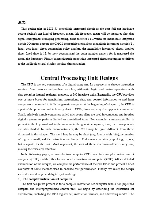
原文:This design take at MCS-51 monolithic integrated circuit as the core full use hardware source design's one kind of frequency meter, this frequency meter will be measured first that signal enlargement reshaping processing, turns satisfies TTL/which the monolithic integrated circuit I/O mouth accepts the CMOS compatible signal from monolithic integrated circuit's T1 input port input direct summation pulse number, the monolithic integrated circuit interior timer fixed time is 1S, by now accumulated the pulse number namely for is measured the signal the frequency. Finally passes through monolithic integrated circuit processing to deliver to the lcd liquid crystal display monitor demonstration.Central Processing Unit DesignsThe CPU is the key component of a digital computer. Its purpose is to decode instruction received from memory and perform transfers, arithmetic, logic, and control operations with data stored in internal registers, memory, or I/O interface units. Externally, the CPU provides one or more buses for transferring instructions, data, and control information to and from components connected to it. In the generic computer at the beginning of chapter 1, the CPU is a part of the processor and is heavily shaded. CPUs, however, may also appear in computers. Small, relatively simple computers called microcontrollers are used in computers and in other digital systems to perform limited or specialized tasks. For example, a microcontroller is present in the keyboard and in the monitor in the generic computer; thus, these components are also shaded. In such microcontrollers, the CPU may be quite different from those discussed in this chapter. The word lengths may be short (say, four or eight bits),the number of registers small, and the instruction sets limited. Performance, relatively speaking, is poor, but adequate for the task. Most important, the cost of these microcontrollers is very low, making their use cost effective.In the following pages, we consider two computer CPUs, one for a complex instruction set computer (CISC) and the other for a reduced instruction set computer (RISC). After a detailed examination of the designs, we compare the performance of the two CPUs and present a brief overview of some methods used to enhance that performance. Finally, we relate the design ideas discussed to general digital system design.1、T he complex instruction set computerThe first design we present is for a complex instruction set computer with a non-pipelined datapath and microprogrammed control unit. We begin by describing the instruction set architecture, including the CPU register set, instruction formats, and addressing modes. TheCISC nature of the instruction set architecture is demonstrated by its memory-to-memory access for data manipulation instructions, eight addressing modes, two instruction format lengths, and instructions that require significant sequences of operations for their execution.We design a datapath for implementing the CISC architecture. The datapath is based on the one initially described in Section 7-9 and incorporated into a CPU in section 8-10. modifications are made to the register file, the function unit, and the buses to support the present instruction set architecture.Once the datapath has been specified, a control unit is designed to complete the implementation of the instruction set architecture. The design of the control unit must involve a coordinated definition of both the hardware organization and the microprogram organization. In particular , dividing the microprogram into microroutines, while at the same time designing the sequencer with which they interact, is a key part of the design. Even the instruction fields and opposed are tied to this coordinated effort. Following the definition of the hardware and microcode organizations, we detail essential parts of the microcode and the microroutines for representative operations.Instruction set architectureFigure 10-1 shows the CISC register set accessible to the programmer. All registers have 16 bits. The register file has eight registers, R0 though R7.R0 is a special register that always supplies the value zero when it is used as a source and discards the result when it is used as a destination.In additional to the register file, there is a program counter PC and stack pointer SP. The presence of a stack pointer indicates that a memory stack is a part of the architecture . the final register is the processor status register PSR, which contains information only in its rightmost the five bits; the remainder of the register is assumed to contain zero. The PSR contains thefour stored status bit values Z,N,C,and V in positions 3 through 0, respectively. In additional, a stored interrupt enable bit EI appears in position 4.Table 10-1 contains the 42 operations performed by the instructions. Each operation has a mnemonic and a carefully selected oppose. The operations are divided into four groups based on the number of explicit operands and whether the operation is branch. In addition, the status bits affected by the operation are listed.Figure 10-2 gives the instruction formats for the CPU. The generic instruction format has five fields. The first, OPCODE, specifies of the operation. The next two, MODE and S , are used to determine the addresses of the operands. The last two fields, SRC and DST, are the 3-bit source register and destination register address fields, respectively. In addition, there is an optional second word W that appears with some instructions as an operand or an address, but not with others.The first two bits of OPCODE, IR(15:14), determine the number of explicit operands and how the fields of the format are used. When these bits are 00,either no operand is required or the location of the operand is implied by OPCODE. Only the OPCODE field is needed, as shown in figure 2(b).the four rightmost OPCODE bits can specify up to 16 operands or with implied operand addresses.If IR(15:14) is 01, the instruction has one operand and is a data transfer or data manipulation instruction. Since there is an operand, the MODE field specifies the addressing mode for obtaining it. The single address may involve the DST register address in its formation, so the DST field is also present. The S field and SRC field relate to the presence of two operands and so are not used for the typical single operand instructions. but, the shift instructions require a shift amount to indicate how many bits to shift. For maximum flexibility,this shift amount is treated just like a source operand. As a consequence, the SHA and S fields is a full 16-bit operand, but only values 0 through 15 are meaningful. There are sufficient OPCODE bits for 16 instructions with a single operand.Table 10-2 gives the addressing modes specified by the MODE field. The first two bits of MODE specify four different types of addressing: register, immediate, indexed, and relative to the PC. The third bit of MODE specifies whether the address generated by these modes is used as an indirect address. The one exception to this is direct addressing, which is obtained by applying indirection to the immediate type. Otherwise, if the third bit equals 0, indirect addressing does not apply whereas, if it equals 1, indirect addressing does apply. For the register type of instruction, MONE(2:1)=00 and the W word is not needed. Since the operand or address comes from a register. The third column of the table provides register transfer statements for each of the addressing modes for the one-operand instructions.If IR(15:14) is equal to 10, then the instruction has two addresses used for true operands. All fields of the generic instruction, including S and SRC, are used for this case for all instructions. one of addresses, either the source or the destination, uses the addressing modes. If S=0, then the source uses the addressing mode specified by MODE, and the source is a register. If S=1, then the destination uses the addressing mode, and the source is a register. Register transfer descriptions of the resulting addresses are given in the fourth and fifth columns of Table 2. Again, depending on the contents of the MODE field, the second instruction word W, which is an address or an immediate operand, may or may not be present.Instructions with IR(15:14)=11 are branches. Aside form the S field and the SHA field for shifts, the format is the same as for IR(15:14)=01. For all instructions of this type, the destination address (not the operand) becomes the new address placed in the program counter PC. As a consequence, the register mode is invalid for branch instructions.Before proceeding to the next step, which defines the datapath to support the instruction set architecture, we will briefly note the characteristics of the architecture that define it as CISC or RISC. Most of the operations given in Chapter 9 are included in the instruction set. A number of operations that do not appear are redundant. The same actions can be achieved by using proper addressing modes with instructions that do appear. For example, LD, ST, IN, and OUT can all be achieved by using MOVE instructions in a memory-mapped structure. By looking at the formats for the instructions, we find that most of the instructions can operate directly on operate directly on operands from memory. There are eight addressing modes and two different lengths of instruction formats. In addition, some of the instructions perform complex operations which can be viewed as operations that are likely to take more than one clo ck cycle for the execution step. These characteristics clearly identify this as a CISC architecture.Datapath organizationRather than beginning from scratch, we will reuse the non-pipelined datapath employed with the microprogrammed control in section 8-10, with modifications. That datapath was shown in section 8-10, and the new, modified datapath based on it is given in Figure 10-6. we treat each modification in turn, beginning with the register file.In section 8-10, register R8 was used as a temporary storage location. In the new microprogrammed architecture, there are complex instructions spanning many clock cycles and performing complicated operations. Thus, more temporary storage is needed for use by the microprograms. To meet this need, we expand the register file from 9 registers to 16. the first 8 registers, R0 through R7, are visible to the computer programmer. The second 8 registers, R8 though R15 , are used as temporary storage for the microprogram operands and are hidden from the programmer. Figure 10-3 provides a map of the expanded register file with the temporary registers shaded. As indicated previously, register R0 supplies the constant 0. registers R1 through R7 are available to the programmer for use, and registers R8 through R15 provide general temporary storage for use by microprograms, the last four registers, R12 though R15, have special uses: to keep the microcode simple, standard locations are essential for storing the operands and addresses used by execution microcode for most instructions. thus ,R12 is the location for the source address(SA), R13 for the source data (SD), R14 for the destination address(DA), and R15 for the destination data(DD).We cannot access the eight temporary registers based on the 3-bit register address available in the instruction. To deal with this problem, we provide, first, 4-bit register address from the microinstruction, and second, a microinstruction bit to choose between these addresses and those from the instruction. In addition, the flexibility to allow the register addressed by DST to be a source and by SRC to be a destination is needed to permit results ofoperations to be placed directly in memory. To accomplish these goals, we modify the register file by adding the logic shown in Figure 10-4(a). the instruction set architecture uses two addresses, one for a source a operand and the other for the other source as well as the destination. The register file uses the B address for a source, and the A and D addresses on the file are connected together, giving the same address for the other source and the destination. Although this reduction from three to two addresses is not essential at the mincroinstruction level, it decrease the number of bits needed for register addresses in the microinstruction and matches the use of the register fields in the instruction formats.A quad 2-to-1 multiplexer is attached to each of the two address inputs to the register file, to select between an address from the microinstruction and an address from the instruction. There is a 5-bit field in the microinstruction for the combined destination and source address DSA, in addition to a 5-bit field for theB address SB. The first bit of each of the these fields selects between the register file address in the microinstruction(0) and the register file address in the instruction(1). If an instruction address is selected, whether it is DST or SRC is determined by an additional quad 2-to-1 multiplexer. This multiplexer is controlled by the second bit of the DSA or SB fields, depending on which of them has 1 in the first bit in any microinstruction, thereby ensuring that the proper second bit is used to determine the register address. A 0 is appended to the left of the 3-bit fields DST and SRC to cause them to address R0 through R7. the addition to the first bit, which selects the address source, the addresses from the microinstruction contain four bits so that all 16 registers can be reached. The final change to the register file is to replace the storage elements for R0 in the file with open circuits on the lines that were their inputs and with constant zero valves on the lines that were their outputs. A symbol for the resulting register file is show in Figure 10-4(b).We find that, based on the eight shift instructions provided, the shifter from section 8-10, needs to be modified. The modifications involve the end bits of the shift logic. For logical shifts, a 0 is inserted, as before. For the right arithmetic shift, she sign bit is the incoming bit, and for the left arithmetic shift, 0 is the incoming bit. Rotates require that the bit from the opposite end of the shifter be fed around. Finally, rotates with carry require that the carry flip-flop output be provide as an input on both ends of the shifter.2.SummaryIn this paper.we examined two CPU designs: the CISC and RISC.The CISC control unit includes a stack pointer in addition to the program counter.Control microprograms reside in ROM.and a combination of a multi.plexer and a ROM provides fast instruction decoding.The control unit also has extensive{ump andconditional branching capabilities,including one level of microsubroutines.The microprogram for the control is modularized to permit many microsubroutines to be shared in implementing the microprogram for the instructions.The RISC control unit is pipelined and has special hardware added to deal with branches. Pipelined CPUs have both data and control hazard problems.We examined one of each type of hazard,as well as software and hardware solutions for each.After discussing CISC and RISC performance,we touched on some advanced concepts, including parallel execution units, a combination of microprogrammed control with a pipeline,superpipelined CPUs, superscalar CPUs,and predictive and speculative techniques for high-performance.Finally, we related the design techniques in this paper to more general digital system design.原文翻译:本设计以MCS-51单片机为核心充分利用硬件资源设计的一种频率计,该频率计首先将被测信号放大整形处理,变成满足单片机I/O口接受的TTL/ CMOS 兼容信号从单片机的T1输入口输入直接累加脉冲数,将单片机内部定时器定时为1S,这时累加的脉冲数即为被测信号的频率。
基于单片机控制的超声波测距系统设计

基于单片机控制的超声波测距系统设计超声波技术是一种非常常用的测距技术,利用超声波在空气中的传播速度和回声原理来实现物体距离的测量。
超声波测距系统是基于这一原理设计的一种系统,可以广泛应用于物体距离的检测和控制领域。
本文将介绍基于单片机控制的超声波测距系统的设计原理、硬件和软件结构,以及系统的性能评估和实际应用。
首先,设计一个基于单片机控制的超声波测距系统需要考虑到硬件的搭建。
该系统主要由超声波发射模块、超声波接收模块、控制单元和显示单元组成。
超声波发射模块用于发送超声波脉冲,超声波接收模块用于接收回波信号。
控制单元则是通过单片机实现对超声波发射和接收模块的控制,同时处理回波信号并计算物体距离。
最后,显示单元用于将测量到的距离值以数字或者图形的形式显示出来。
在硬件搭建的基础上,还需要设计适合的软件算法来实现距离的测量和显示。
首先需要编程单片机实现对超声波发射和接收模块的控制,包括超声波信号的发送和接收,以及回波信号的处理和距离的计算。
在距离的计算方面,需要考虑到超声波在空气中的传播速度,同时考虑到超声波发射和接收模块之间的时间差,从而计算出物体到超声波发射模块的距离。
除了硬件和软件的设计,还需要对系统的性能进行评估。
主要包括系统的精度、测量范围、响应时间和稳定性等方面的评估。
可以通过实验测量不同距离下系统的测量误差,以及系统在不同环境条件下的表现,从而评估系统的性能是否符合实际应用的需求。
在实际应用方面,基于单片机控制的超声波测距系统可以应用于智能家居控制、无人驾驶汽车、智能仓储管理等方面。
例如,可以将该系统应用于智能家居中,通过测量门口到来访者的距离来实现自动开关门的控制;或者可以将该系统应用于无人驾驶汽车中,实现对周围物体距离的检测和避障控制。
梳理一下本文的重点,我们可以发现,在实际应用中具有很大的潜力和广泛的应用前景。
通过合理的硬件和软件设计,以及系统性能评估和实际应用探索,可以更好地发挥该系统在物体距离测量和控制领域的作用。
自动化专业 单片机相关 外文文献 英文文献 外文翻译中英对照
本科生毕业论文(外文翻译) 译文名称:MCS -51 系列单片机的功能和结构专业:自动化班次:学员:指导教员:评阅人:完成时间:2022 年11 月30 日Structure and function of the MCS-51 series Structure and function of the MCS-51 series one-chip computer is a name ofa piece of one-chip computer series which Intel Company produces. This company introduced 8 top-grade one-chip computers of MCS-51 series in 1980 after introducing 8 one-chip computers of MCS-48 series in 1976. It belong to alot of kinds this line of one-chip computer the chips have,such as 8051, 8031, 8751, 80C51BH, 80C31BH,etc., their basic composition, basic performance and instruction system are all the same. 8051 daily representatives- 51 serial one-chip computers .An one-chip computer system is made up of several following parts: ( 1) One microprocessor of 8 (CPU). ( 2) At slice data memory RAM (128B/256B),it use not depositting not can reading /data that write, such as result not middle of operation, final result and data wanted to show, etc. ( 3) Procedure memory ROM/EPROM (4KB/8KB ), is used to preserve the procedure , some initial data and form in slice. But does not take ROM/EPROM within some one-chip computers, such as 8031 , 8032, 80C ,etc.. ( 4) Four 8 run side by side I/O interface P0 four P3, each mouth can use as introduction , may use as exporting too. ( 5) Two timer / counter, each timer / counter may set up and count in the way, used to count to the external incident, can set up into a timing way too, and can according to count or result of timing realize the control of the computer. ( 6) Five cut off cutting off the control system of the source . ( 7) One all duplexing serial I/O mouth of UART (universal asynchronous receiver/transmitter (UART) ), is it realize one-chip computer or one-chip computer and serial communication of computer to use for. ( 8) Stretch oscillator and clock produce circuit, quartz crystal finely tune electric capacity need outer. Allow oscillation frequency as 12 megahertas now at most. Every the above-mentioned part was joined through the inside data bus .Among them, CPU is a core of the one-chip computer, it is the control of the computer and command centre, made up of such parts as arithmetic unit and controller , etc.. The arithmetic unit can carryon 8 persons of arithmetic operation and unit ALU of logic operation while including one, the 1 storing device temporarilies of 8, storing device 2 temporarily, 8's accumulation device ACC, register B and procedure state register PSW, etc. Person who accumulate ACC count by 2 input ends entered of checking etc. temporarily as one operation often, come from person who store 1 operation is it is it make operation to go on to count temporarily , operation result and loopback ACC with another one. In addition, ACC is often regarded as the transfer station of data transmission on 8051 inside . The same as general microprocessor, it is the busiest register. Help remembering that agreeing with A expresses in the order. The controller includes the procedure counter , the order is depositted, the order decipher, the oscillator and timing circuit, etc. The procedure counter is made up of counter of 8 for two, amounts to 16. It is a byte address counter of the procedure in fact, the content is the next IA that will carried out in PC. The content which changes it can change the direction that the procedure carries out . Shake the circuit in 8051 one-chip computers, only need outer quartz crystal and frequency to finely tune the electric capacity, its frequency range is its 12MHZ of 1.2MHZ. This pulse signal, as 8051 basic beats of working, namely the minimum unit of time. 8051 is the same as other computers, the work in harmony under the control of the basic beat, just like an orchestra according to the beat play that is commanded.There are ROM (procedure memory , can only read ) and RAM in 8051 slices (data memory, can is it can write ) two to read, they have each independent memory address space, dispose way to be the same with general memory of computer. Procedure 8051 memory and 8751 slice procedure memory capacity 4KB, address begin from 0000H, used for preserving the procedure and form constant. Data 8051- 8751 8031 of memory data memory 128B, address false 00FH, use for middle result to deposit operation, the data are stored temporarily and the data are buffered etc.. In RAM of this 128B, there is unit of 32 byteses that can be appointed as the job register, this and generalmicroprocessor is different, 8051 slice RAM and job register rank one formation the same to arrange the location. It is not very the same that the memory of MCS-51 series one-chip computer and general computer disposes the way in addition. General computer for first address space, ROM and RAM can arrangein different space within the range of this address at will, namely the addressesof ROM and RAM, with distributing different address space in a formation. While visiting the memory, corresponding and only an address Memory unit, can ROM, it can be RAM too, and by visiting the order similarly. This kind of memory structure is called the structure of Princeton. 8051 memories are divided into procedure memory space and data memory space on the physics structure, there are four memory spaces in all: The procedure stores in one and data memory space outside data memory and one in procedure memory space and one outside one, the structure forms of this kind of procedure device and data memory separated form data memory, called Harvard structure. But use the angle from users, 8051 memory address space is divided into three kinds: (1) In the slice, arrange blocks of FFFFH , 0000H of location , in unison outside the slice (use 16 addresses). (2) The data memory address space outside one of 64KB, the address is arranged from 0000H 64KB FFFFH (with 16 addresses ) too to the location. (3) Data memory address space of 256B (use 8 addresses). Three above-mentioned memory space addresses overlap, for distinguishing and designing the order symbol of different data transmission in the instruction system of 8051: CPU visit slice, ROM order spend MOVC , visit block RAM order uses MOVX outside the slice, RAM order uses MOV to visit in slice.8051 one-chip computer have four 8 walk abreast I/O port, call P0, P1, P2 and P3. Each port is 8 accurate two-way mouths, accounts for 32 pins altogether. Every one I/O line can be used as introduction and exported independently. Each port includes a latch (namely special function register ), one exports the driver and a introduction buffer . Make data can latch when outputting, data can buffer when making introduction , but four function of passway these self-same.Expand among the system of memory outside having slice, four port these may serve as accurate two-way mouth of I/O in common use. Expand among the system of memory outside having slice, P2 mouth see high 8 address off; P0 mouth is a two-way bus, send the introduction of 8 low addresses and data / export in timesharingThe circuit of 8051 one-chip computers and four I/O ports is very ingenious in design. Familiar with I/O port logical circuit, not only help to use ports correctly and rationally, and will inspire to designing the peripheral logical circuit of one-chip computer to some extent. Load ability and interface of port have certain requirement, because output grade, P0 of mouth and P1 end output, P3 of mouth grade different at structure, so, the load ability and interface of its door demand to have nothing in common with each other. P0 mouth is different from other mouths, its output grade draws the resistance supremly. When using it as the mouth in common use to use, output grade is it leak circuit to turn on, is it is it urge NMOS draw the resistance on taking to be outer with it while inputting toEvery one with P0 mouth can drive 8 Model LS TTL load to export. P1 mouth is an accurate two-way mouth too, used as I/O in common use. Different from P0 mouth output of circuit its, draw load resistance link with power on inside have. In fact, the resistance is that two effects are in charge of FET and together: One FET is in charge of load, its resistance is regular. Another one can is it lead to work with close at two state, make its President resistance value change approximate 0 or group value heavy two situation very. When it is 0 that the resistance is approximate , can draw the pin to the high level fast ; When resistance value is very large, P1 mouth, in order to hinder the introduction state high. Output as P1 mouth high electricity at ordinary times, can is it draw electric current load to offer outwards, draw the resistance on needn't answer and thenning. Here when the port is used as introduction, must write into 1 to the corresponding latch first too, make FET end. Relatively about 20,000 ohmsbecause of the load resistance in scene and because 40,000 ohms, will not exert an influence on the data that are input. The structure of P2 some mouth is similar to P0 mouth, there are MUX switches. Is it similar to mouth partly to urge, but mouth large a conversion controls some than P1. P3 mouth one multi-functionalthese, make her besides accurate two-way function with P1 mouth just, can alsodetermines to be to output data of latch to output second signal of function. Act as W =At 1 o'clock, output Q end signal; Act as Q =At 1 o'clock, can output W line signal . At the time of programming, it is that the first function is still the second function but needn't have software that set up P3 mouth in advance . It hardware not inside is the automatic to have two function outputted when CPU carries on SFR and seeks the location (the location or the byte ) to visit to P3 mouth /at not lasting lining, there are inside hardware latch Qs =1.The operation principle of P3 mouth is similar to P1 mouth.Output grade , P3 of mouth , P1 of P1 , connect with inside have load resistance of drawing , every one of they can drive 4 Model LS TTL load to output. As while inputting the mouth, any TTL or NMOS circuit can drive P1 of 8051 one-chip computers as P3 mouth in a normal way . Because draw resistance on output grade of them have, can open a way collector too or drain-source resistance is it urge to open a way, do not need to have the resistance of drawing outerly . Mouths are all accurate two-way mouths too. When the conduct is input, must write the corresponding port latch with 1 first . As to 80C51 one-chip computer, port can only offer milliampere of output electric currents, is it output mouth go when urging one ordinary basing of transistor to regard as, should contact a resistance among the port and transistor base , in order to the electricity while restraining the high level from exporting P1~P3 Being restored to the throne is the operation of initializing of an one-chip computer. Its main function is to turn PC into 0000H initially , make theone-chip computer begin to hold the conduct procedure from unit 0000H. Except that the ones that enter the system are initialized normally,as because procedure operate it make mistakes or operate there aren't mistake, in order to extricate oneself from a predicament , need to be pressed and restored to the throne the key restarting too. It is an input end which is restored to the throne the signal in 8051 China RST pin. Restore to the throne signal high level effective , should sustain 24 shake cycle (namely 2 machine cycles ) the above its effective times. If 6 of frequency of utilization brilliant to shake, restore to the throne signal duration should exceed 4 delicate to finish restoring to the throne and operating. Produce the logic picture of circuit which is restored to the throne the signal:Restore to the throne the circuit and include two parts outside in the chip entirely. Outside that circuit produce to restore to the throne signal (RST ) hand over to Schmitt's trigger, restore to the throne circuit sample to output , Schmitt of trigger constantly in each S5P2 , machine of cycle in having one more , then just got and restored to the throne and operated the necessary signal insidly. Restore to the throne resistance of circuit generally, electric capacity parameter suitable for 6 brilliant to shake, can is it restore to the throne signal high level duration greater than 2 machine cycles to guarantee. Being restored to the throne in the circuit is simple, its function is very important. Pieces of one-chip computer system could normal running,should first check it can restore to the throne not succeeding. Checking and can pop one's head and monitor the pin with the oscillograph tentatively, push and is restored to the throne the key, the wave form that observes and has enough range is exported (instantaneous), can also through is it restore to the throne circuit group holding value carry on the experiment to change.MCS -51 系列单片机的功能和结构MCS - 51 系列单片机具有一个单芯片电脑的结构和功能,它是英特尔公司生产的系列产品的名称。
基于单片机的超声波测距系统的设计

基于单片机的超声波测距系统的设计引言超声波测距技术是一种常用的非接触式测距方法,广泛应用于工业自动化、无人驾驶、智能家居等领域。
本文将介绍基于单片机的超声波测距系统的设计原理和实现方法,以及其在实际应用中的优势和局限性。
一、设计原理基于单片机的超声波测距系统主要由超声波发射器、接收器、单片机和显示装置组成。
其工作原理如下:1.1 超声波发射器发射超声波信号,信号经过空气传播后,被目标物体反射返回。
1.2 超声波接收器接收到反射的超声波信号,并将信号转化为电信号。
1.3 单片机通过IO口控制超声波发射器的工作频率和接收器的工作模式,实现信号的发射和接收。
1.4 单片机通过计算超声波信号的往返时间,即可得到目标物体与传感器之间的距离。
1.5 显示装置将测得的距离信息显示出来,供用户参考和使用。
二、系统设计与实现2.1 硬件设计超声波发射器和接收器的选型是系统设计的关键。
通常情况下,超声波发射器和接收器的工作频率应匹配,常用的频率有40kHz和50kHz。
此外,还需选择合适的单片机和显示装置。
2.2 软件设计软件设计主要包括超声波信号的发射和接收控制以及距离计算等功能。
通过编程,可以实现以下功能:2.2.1 控制超声波发射器的工作频率和接收器的工作模式。
2.2.2 通过IO口读取接收器接收到的信号,并将其转化为数字信号。
2.2.3 使用定时器测量超声波信号的往返时间。
2.2.4 根据往返时间计算目标物体与传感器之间的距离。
2.2.5 将测得的距离信息显示在显示装置上。
三、系统优势基于单片机的超声波测距系统具有以下优势:3.1 非接触式测距:超声波测距系统可以实现对目标物体的非接触式测距,无需直接接触目标物体,避免了传感器与目标物体之间的摩擦和磨损。
3.2 高精度:超声波测距系统通过测量超声波信号的往返时间,可以实现较高的测距精度,通常可达到毫米级别。
3.3 快速响应:超声波测距系统的测量速度快,响应时间短,适用于需要快速测量的应用场景。
「基于单片机的超声波测距系统的研究与设计」
第1章绪论1.1课题背景目的及重要意义随着科学技术的快速发展,超声波将在传感器中的应用越来越广。
在人类文明的历次产业革命中,传感技术一直扮演着先行官的重要角色,它是贯穿各个技术和应用领域的关键技术,在人们可以想象的所有领域中,它几乎无所不在[M]。
传感器是世界各国发展最快的产业之一,在各国有关研究、生产、应用部门的共同努力下,传感器技术得到了飞速的发展和进步。
但就目前技术水平来说,人们可以具体利用的传感技术还十分有限,因此,这是一个正在蓬勃发展而又有无限前景的技术及产业领域。
超声波测距与其它非接触式的检测方式方法相比,如电磁的或光学的方法它不受光线,被测对象颜色,电磁干扰等影响。
超声波对于被测物体处于黑暗,有灰尘,烟雾,电磁干扰,有毒等恶劣的环境有一定的适应能力。
因此在液位测量,机械手控制,车辆自动导航,物体识别等方面有广泛应用。
特别是应用于空气测距,由于空气中波速较慢,其回波信号中包含的沿传播方向上的结构信息很容易检测出来,具有很高的分辩力,因而其准确度也较其它方法高,而且超声波传感器具有结构简单,体积小,信号处理可靠等特点。
超声波是一种指向性强,能量消耗慢的波。
它在介质中传播的距离较远。
因而超声波经常用于距离的测量,可解决超长度的测量。
超声波作为一种特殊的声波,同样具有声波传输的基本物理特性,反射,折射,干涉,衍射,散射。
与物理紧密联系,应用灵活。
并且更适合与高温,高粉尘,高湿度和高强电磁干扰等恶劣环境下工作。
超声波可用于非接触测量,具有不受光、电磁波以及粉尘等外界因素的干扰的优点,是利用计算超声波在被测物体和超声波探头之间的传输来测量距离的,对被测目标无损害。
而且超声波传播速度在相当大范围内与频率无关[J]。
超声波的这些独特优点越来越受到人们的重视。
在新的世纪里,面貌一新的传感器将发挥更大的作用课程设计目的是单片机原理与接口技术课程设计是在教学及实验基础上,对课程所学理论知识的深化和提高。
基于单片机的超声波测距系统设计毕业论文

目录
第一章 绪论
超声波是指频率在 20kHz 以上的声波,它属于机械波的范畴。超声波也遵循一般机械 波在弹性介质中的传播规律,如在介质的分界面处发生反射和折射现象,在进入介质后被介 质吸收而发生衰减。它也有自已的特性,如它的频率可以非常高,达到兆赫级,因此,它在 介质中传播时能量可以集中在很小的范围内,具有良好的成束性,也就是方向性好。
器人的研究上得到了广泛的应用。同时由于超声波测距系统具有以上的这些优 点,因此在汽车倒车雷达的研制方面也得到了广泛的应用。
1.3 国内外相关研究情况 国内的超声波测[3]量主要集中在对 0~10 m 固体和液体的测量,一般测量精度 高,回波稳定[4]。近年来随着超声波技术研究的不断深入已广泛应用于各种工业 领域,如工业自动控制,建筑工程测量和机器人视觉识别等方面。此外在材料科 学、医学、生物科学等领域中也占据重要地位。 国外在提高超声波测距方面做了大量的研究,国内的一些学者也作了大量相 关的研究。 南昌航空工业学院的江泽涛[5]在《温度对液体中超声波速度的影响》一文中, 洋细地分析了温度对超声波在液体中传播速度的影响,导出了超声波速度同液体 压缩系数及密度的关系,研究了压缩系数及密度同温度的关系,进而研究了温度 对声速及声时的影响, 用实验测量了不同的液体成分下的声时同温度的关系。 Figneroa J.F.,Lamancusa J.S.[6]在《A method for accurate detection of time of arrival:AnalysiS and design of ultrasonic ranging system} 一文中,提出一种新的计时方法,该方法的原理是回波时延由峰值时延和相位时 延相加而得,分别用不同的检测方法得到峰值时延和相位时延,相加后即得回波 的传播时间。
基于单片机控制的超声波传感器的系统设计论文(含中英文翻译资料)

基于单片机控制的超声波传感器的系统设计论文(含中英文翻译资料)摘要化石能源是不可再生能源,随着人类工业化进程的发展,对能源的消耗量与日俱增。
人类已经面临着能源枯竭的危险,且在短期内难以改变对化石能源的依赖。
但是我们可以做一些努力,减少对能源的浪费。
目前的餐饮业,厨房均使用带鼓风机的燃气、燃油炒菜炉灶。
这些炉灶烹饪菜的过程中每炒一道菜约有50%-60% 的累积时间是空烧的,这是一种浪费。
此研究就是为了减少这种浪费。
在这里我们主要研究饭店里大量使用的燃油灶,在燃油灶上加装一个控制系统,以达到不改变厨师的操作习惯而由控制系统自动达到节能的目的。
本文主要研究了基于超声波的单片机节能控制电路,由单片机发出40KHZ的脉冲信号经由功放以驱动超声波探头。
再由探头接收回波,经过一系列的处理形成中断信号已达到测距的目的。
由测得的距离值来判断是否执行节能操作,以达到节能控制的目的。
关键词节能;单片机;超声波;自动化AbstractFossil fuel is can not renewable sources of energy,with the development of industrialisation progress along with the human being,Increasing wastage of the fuel with each passing day 。
The human being have already faced dried up risk of fuel,And in the short run it is hard alteration to lean of fossil fuel。
But we can commit some effort,Cuting the waste to the fuel。
Current dining industry,Kitchen all employ that burnting gas, burnting oil cooking range with blower。
基于单片机的外文翻译
Presented in this paper is a design of pulse measuring instrument based on MCU, as the circuit module plays an important role in the system, such as heart rate acquisition circuit, display circuit and STC89C52 microcontroller through the serial port to realize the connection. This design with STC89C52 microcontroller as the central control unit, through ST188 as infrared photoelectric sensor to collect the pulse signal, after the lm358 for op amp; again through before and after filtering, magnifying, shaping, and get stable signal; functions to achieve the rapid detection of heart. You can also through the button to set the pulse value scope; buzzer driver module In the range beyond the scope of the alarm prompt, the measurement results in the liquid crystal display.Experimental results show that the test results of the design and practical requirements are basically the same, STC89C52 MCU strong anti-interference ability and LCD1602 display control the advantages of more convenient so that these features can be successfully completed. The production cost less than 100 yuan, with low price, easy manipulation, low power consumption, high reliability, very applicable to families and individuals.Heart rate) in professional terms is used to describe the human heart beat cycle. Pulse of modern Chinese will be interpreted as "heart beating frequency value; so the heart rate can also said in a unit of time, heart rhythm speed.Everyone's heart rate signals mostly contains rich physiological and psychological information. This is due to the health of internal organs of the body can reflect in the pulse information. This discovery has gradually attracted the attention of many clinicians. In our country, pulse diagnosis has been regarded as the essence of Chinese medicine; so far the clinical practice has about 2600 years. However due to the use of fingers often there will be some sweat glands refers to pulse diagnosis in the presence of errors can not be ignored; and leads to inaccurate measurement. Then perhaps you would say and the ear vein measurement, instead of the previous is often used. Although by measuring ear ripple come to pulse signal relatively comparison Clean, but because the ear pulse signal is weak, especially when the seasonal changes, the measurement signal is vulnerable to the influence of environmental temperature,resulting in inaccurate measurement values.With the development and progress of world science and technology and economy, cherish life, health care has become a common pursuit of mankind throughout the world. According to the Health Bureau statistics, every year because of cardiovascular and cerebrovascular diseases death of the highest number of human deaths first, not only the high cost of health care, back to the family, the government and the society caused great burden. In recent years, due to the accelerated pace of life, unreasonable eating habits and many junk food impact and other reasons, the incidence of cardiovascular and cerebrovascular is showing a trend of rising year by year. How to scientifically and harmless reduce cardiovascular disease morbidity and mortality, effectively reduce cardiovascular and cerebrovascular diseases and social Family burden, has become a very serious problem faced by human beings all over the world.World first lever type pulse scanner is Vierordt was founded in 1854. It is a lever and a pressure drum scanner uses the notation to record the pulse waveform, also is the human for the first time through non invasion of recording the human body pulse, then caused a great sensation. However the starting point for the development of domestic relatively is relatively low, in the early 50s of the 20th century Zhu Yancai will pulse instrument reference to objective study on the pulse diagnosis in traditional Chinese medicine. In recent years, non invasive vascular function detection gradually attracted the eyes of the medical professionals. Since about 1980, no trauma vascular function detection by using the small range, its principle is roughly Based on hemodynamic rheology theory and elastic chamber theory. Characterized in it by the module temperature, blood pressure cuff module, blood oxygen module of multi physiological signal acquisition module combination by of brachial artery blocking opening in the process of finger end temperature signal, oxygen saturation and pulse wave signal changes of the parameters of the, again according to the clinical trial data acquisition and through the method of signal processing and statistical analysis, establishment of vascular function quantitative evaluation formula and blood vessel function evaluation. It has noninvasive, simple operation, accurate, good repeatability and convenient for clinical application and automatically generates diagnosis ofcardiovascular function, health status analysis and gives related medical solution Release.Now pulse testing is no longer confined to the traditional manual testing or stethoscope test, only use electronic devices can be obtained more accurate data. In today's society, most of electronic measuring instruments has been directed towards the digitization, automation development direction. Pulse measuring instrument is not only good performance, simple structure, and has good value of application and popularization. In general, the pulse measurement instrument development is mainly the following trends: first, in the absence of human can automatically analyze the measurement of pulse value; the pulse of the traditional instrument need after experienced doctor pulse signal of the first initial analysis and then make a comprehensive analysis to final To confirm the results, this method of total said to not only waste a lot of manpower and by factitious error is relatively large. The second: the wide application of digital technology and other advanced technology; pulse measuring instrument integration to want to achieve a higher degree, and are more convenient to carry must rely on the rapid development of digital science and technology; at the same time digital signal processing application will enable interference becomes smaller measurement result is more accurate. The third: multi function of more and more obvious. The fourth: cheap, easy to carry and application and popularization value better, to the general public convenience.Has always been in the hospital for basis for clinical diagnosis and treatment of most source extracted from the human pulse wave in physiological and pathological information. In China, feeling the pulse is old doctor of traditional Chinese medicine is the most commonly used to diagnose disease, has been in use ever since. The pulse signal emitted by human body contains the velocity of heart rate, full waveform, period and amplitude, a full range of integrated information, in a large extent can reflect human body each part information (for example blood viscosity, blood velocity). Although these biological signals exist in the human body, the signal intensity relative to said is relatively weak; if in a noisy environment effect is more obvious.This graduation design principle is the use of single-chip microprocessorSTC89C52 as the center processor; pulse signal is collected by the sensor, through the microcontroller chip in the interior of the system timer to set the time; finally get the heart rate beat numerical by STC89C52 microcontroller to signal accumulation can be. Normal heartbeat is about 60-100 per minute times, circuit diagram of key module can through the button to set the scope of people's heart rate, above or below the setting range of possible heart there will be risks, buzzer driver module will drive buzzer alarm; the final measurement results Will be displayed on the LCD. The design can by viewing the IR indicates whether the lights and flashing, if sustained, stable flashing that test results are correct and error is small. With the assumption that the display results back and forth rock and numerical difference between the larger, there may exist error. Through the above steps, can roughly determine the body's own health, and is particularly suitable to be used to the individual or family, is also sometimes used in nursing homes and healthcare center.The design of the selection of SCM is STC89C52。
(完整版)_毕业设计英文文献51单片机中英文文献翻译_

AT89C51的概况The General Situation of AT89C51Chapter 1 The application of AT89C51Microcontrollers are used in a multitude of commercial applications such as modems, motor-control systems, air conditioner control systems, automotive engine and among others. The domains also require that these microcontrollers are be ensured by a robust testing process and a proper tools environment for the validation of these microcontrollers both at the component and at the system level. Intel Plaform Engineering department developed anobject-oriented multi-threaded test environment for the validation of its AT89C51 automotive microcontrollers. The goals of thisenvironment was not only to provide a robust testing environment for the AT89C51 automotive microcontrollers, but to develop an environment which can be easily extended and reused for the validation of several other future microcontrollers. The environment was developed in conjunction with Microsoft Foundation Classes (AT89C51). The paper describes the design and mechanism of this test environment, its interactions with variousThe 8-bit AT89C51 CHMOS microcontrollers are designed to engine-control systems, airbags, suspension systems, and antilock braking systems (ABS). The AT89C51 is especially well suited to applications that benefit from its processing speed and enhancedon-chip peripheral functions set, such as automotive power-train control, vehicle dynamic suspension, antilock braking, and stability control applications. Because of these critical applications, the market requires a reliable cost-effective controller with a low interrupt latency response, ability to service the integrated peripherals needed in real time applications, and a CPU with above average processing power in a single package. The financial and legal risk of the market, particularly in mission criticalapplications such as an autopilot or anti-lock braking system, mistakes are financiallyprohibitive. Redesign costs can run as flaw. In addition, field replacements of components is extremely expensive, as the devices are typically sealed in modules with a total value several times that of the component. To mitigate these problems, it is essential that comprehensive testing of the controllers be carried out at both the component level and system level under worst case environmental and voltage conditions.This complete and thorough validation necessitates not only a well-defined process but also a proper environment and tools to facilitate and execute the mission successfully.Intel Chandler Platform Engineering group provides post silicon system validation (SV) of various micro-controllers and processors. The system validation process can be broken into three major parts.The type of the device and its application requirements determine which types of testing are performed on the device.1.2 The AT89C51 provides the following standard features:4Kbytes of Flash, 128 bytes of RAM, 32 IO lines, two 16-bittimercounters, a five vector two-level interrupt architecture,a full duple ser -ial port, on-chip oscillator and clock circuitry.In addition, the AT89C51 is designed with static logic for operation down to zero frequency and supports two software selectable power saving modes. The Idle Mode stops the CPU while allowing the RAM, timercounters,serial port and interrupt sys -tem to continue functioning. The Power-down Mode saves the RAM contents but freezes the oscil –lator disabling all other chip functions until the next DescriptionVCC Supply voltage.GND Ground.Port 0:Port 0 is an 8-bit open-drain bi-directional IO port. As an output port, each pin cansink eight TTL inputs. When 1s are written to port 0 pins, the pins can be used as this mode P0 . External pullups are required during programverification.Port 1:Port 1 is an 8-bit bi-directional IO port with internal pullups.The Port 1 output buffers can sinkso -urce four TTL inputs.When 1s are written to Port 1 pins they are pulled be used as inputs. As inputs, Port 1 pins that are externally being pulled low will source current (IIL) because of the internal pullups.Port 1 also receives the low-order address bytes during Flash programming and verification.Port 2:Port 2 is an 8-bit bi-directional IO port with internal pullups.The Port 2 outputbuffers can sinksource four TTL inputs.When 1s are written to Port 2 pins they arepulled be used as inputs. As inputs, Port 2 pins that are externally being pulled low will source current (IIL) because of the internal pullups. Port 2 emits the this application, it uses strong internal pull-ups when emitting 1s. During accesses to external data memory that use 8-bit addresses (MOVX @ RI), Port 2 emits the contents of the P2 Special Function Register.Port 2 also receives the Flash programming and verification.Port 3:Port 3 is an 8-bit bi-directional IO port with internal pullups.The Port 3 outputbuffers can sinksou -rce four TTL inputs.When 1s are written to Port 3 pins they are pulled be used as inputs. As inputs,Port 3 pins that are externally being pulled low will source current (IIL) because of the pullups.Port 3 also serves the functions of various special featuresof the AT89C51 as listed below:RST:Reset input. A this pin for two machine cycles while the oscillator is running resets the device.ALEPROG:Address Latch Enable output pulse for latching the low byte of the address duringaccesses to external memory.This pin is also the program pulse input (PROG) during Flash programming.In normal operation ALE is emitted at a constant rate of 16 the oscillator frequency,and may be used for external timing or clocking purposes. Note, be disabled by setting bit 0 of SFR location 8EH.With the bit set, ALE is active onlyduring a MOVX or MOVC instruction. Otherwise, the pin is weakly pulled external execution mode.PSEN:Program Store Enable is the read strobe to external program memory. When theAT89C51 is executing code from external program memory, PSEN is activated twiceeach machine cycle, except that two PSEN activations are skipped during each access toexternal data memory.EAVPP:External Access Enable. EA must be strapped to GND in order to enable the deviceto fetch code from external program memory locations starting at 0000H up to FFFFH.Note, alsreceives the 12-volt programming enable voltage (VPP) during Flash programming, forparts that require 12-volt VPP.XTAL1:Input to the inverting oscillator amplifier and input to the internal clock operatingcircuit.XTAL2:Output from the inverting oscillator amplifier.Oscillator CharacteristicsXTAL1 and XTAL2 are the input and output, respectively, of an inverting amplifierwhich can be configured for use as an on-chip oscillator, as shown in Figure 1. Either aquartz crystal or ceramic resonator may be used. To drive the device from an externalclock source, XTAL2 should be left unconnected while XTAL1 is driven as shown in Figure 2.There are no requirements on the duty cycle of the external clock signal, since the input to the internal clocking circuitry is through a divide-by-two flip-flop, but minimum and maximum voltage idle mode, the CPU puts itself to sleep while all the onchip peripherals remainactive. The mode is invoked by software. The content of the on-chip RAM and all the special functions registers remain unchanged during this mode. The idle mode can be terminated by any enabled interrupt or by a idle is terminated by a ,from where it left off, up to two machine cycles before the internal reset algorithm takes control. On-chip this event, but access to the port pins is not inhibited. To eliminate the possibility of an unexpected write to a port pin when Idle is terminated by reset, the instruction following the one that invokes Idle should not be one that writes to a port pin or to external memory.Power-down ModeIn the power-down mode, the oscillator is stopped, and the instruction that invokes power-down is the last instruction executed. The on-chip RAM and Special Function Registers retain their values until the power-down mode is terminated. The only exit from power-down is a -chip RAM. The reset should not be activated before VCC is restored to its normal operating level and must be either programming mode. To program any nonblank byte in the on-chip Flash Memory, the entire memory must be erased using the Chip Erase Mode.2 Programming AlgorithmBefore programming the AT89C51, the address, data and control signals should be set up according to the Flash programming mode table and Figure 3 and Figure 4. To program the AT89C51, take the following steps.1. Input the desired memory location on the addresslines.2. Input the appropriate data byte on the data lines. 3. Activate the correct combination of control signals. 4. Raise EAVPP to 12V for the the Flash array or the lock bits. The byte-write cycle is self-timed and typically takes no more than 1.5 ms. Repeat steps 1 through 5, changing the address and data for the entire array or until the end of the object file is reached. Data Polling: The AT89C51 features Data Polling to indicate the end of a write cycle. During a write cycle, an attempted read of the last byte written will result in the complement of the written datum on PO.7. Once the write cycle completed, true data are valid on all outputs, and the next cycle may begin. Data Polling may begin any time after a write cycle initiated.2.1ReadyBusy:The progress of byte programming can also be monitored by the RDYBSY output signal. P3.4 is pulled low after ALE goes when programming is done to indicate READY.Program Verify:If lock bits LB1 and LB2 programmed, the programmed code data can be read back via the address and data lines for verification. The lock bits cannot be verified directly. Verification of the lock bits is achieved by observing that their features are enabled.Figure 2-1-1 Programming the Flash Figure 2-2-2 Verifying the Flash2.2 Chip Erase:The entire Flash array is erased electrically by using the proper combination of control signals and by with all “1”s. The chip erase operation must be executed before the code memory can be re-programmed.2.3 Reading the Signature Bytes:The signature bytes are read by the same procedure as a normal verification of locations 030H, 031H, and 032H, except that P3.6 and P3.7 must be pulled to a logic low. The values returned areas follows.(030H) = 1EH indicates manufactured by Atmel(031H) = 51H indicates 89C51(032H) = FFH indicates 12V programming(032H) = 05H indicates 5V programming2.4 Programming InterfaceEvery code byte in the Flash array can be written and the entire array can be erased by using the appropriate combination of control signals. The write operation cycle is selftimed and once initiated, will automatically time itself to completion. A microcomputer interface converts information between two forms. Outside the microcomputer the information electronic system exists as a physical signal, but within the program, it is represented numerically. The function of any interface can be broken down into a number of operations which modify the data in some way, so that the process of conversion between the external and internal forms is carried out in a number of steps. An analog-to-digital converter(ADC) is used to convert a continuously variable signal to a corresponding digital form which can take any one of a fixed number of possible binary values. If the output of the transducer does not vary continuously, no ADC is necessary. In this case the signal conditioning section must convert the incoming signal to a form which can be connected directly to the next part of the interface, the inputoutput section of the microcomputer itself. Output interfaces take a similar form, the obvious difference being that is in the opposite direction; it is passed from the program to the outside world. In this case the program may call an output subroutine which supervises the operation of the interface andperforms the scaling numbers which may be needed for digital-to-analog converter(DAC). This subroutine passesinformation in turn to an output device which produces a corresponding electrical signal, which could be converted into analog form using a DAC. Finally the signal is conditioned(usually amplified) to a form suitable for operating an actuator.The signals used within microcomputer circuits are almost always too small to be connected directly to the outside world” and some kind of interface must be used to translate them to a more appropriate form. The design of section of interface circuits is one of the most important tasks facing the engineer wishing to apply microcomputers. We that in microcomputers information is represented as discrete patterns of bits; this digital form is most useful when the microcomputer is to be connected to equipment which can only be switched on or off, where each bit might represent the state of a switch or actuator. To solve real-world problems, a microcontroller must just a CPU, a program, and a data memory. In addition, it must contain from the outside world. Once the CPU gathers information and processes the data, it must also be able to effect change on some portion of the outside world. These microcontrollers is the general purpose I70 port. Each of the IO pins can be used as either an input or an output. The function of each pin is determined by setting or clearing corresponding bits in a corresponding data direction register during the initialization stage of a program. Each output pin may be driven to either a logic one or a logic zeroby using CPU instructions to pin may be viewed (or read.) by the CPU using program instructions. Some type of serial unit is included on microcontrollers to allow the CPU to communicate bit-serially with external devices. Using a bit serial format instead of bit-parallel format requires fewer IO pins to perform the communication function, which makes it less expensive, but slower.Serial transmissions are performed either synchronously orasynchronously.翻译AT89C51的概况1 AT89C51应用单片机广泛应用于商业:诸如调制解调器,电动机控制系统,空调控制系统,汽车发动机和其他一些领域。
单片机-外文翻译-外文文献-英文文献-基于单片机的超声波测距系统的研究与设计

附录附录A外文翻译the equivalent dc value。
In the analysis of electronic circuits to be considered in a later course, both dc and ac sources of voltage will be applied to the same network。
It will then be necessary to know or determine the dc (or average value)and ac components of the voltage or current in various parts of the system.EXAMPLE 13.13 Determine the average value of the waveforms of Fig。
13.37。
FIG。
13。
37Example 13。
13。
Solutions:a. By inspection, the area above the axis equals the area below over one cycle,resulting in an average value of zero volts.b。
Using Eq。
(13.26):as shown in Fig。
13。
38.In reality, the waveform of Fig. 13。
37(b)is simply the square wave of Fig. 13。
37(a) with a dc shift of 4 V; that is v2 =v1 + 4 VEXAMPLE 13.14 Find the average values of the following waveforms over one full cycle:a.Fig. 13。
毕业设计论文 外文文献翻译 超声波测距 中英文对照
毕业设计论文外文文献翻译超声波测距中英文对照The Circuit Design of UltrasonicRanging System超声波测距系统的电路设计Ultrasonic Distance Meter超声波测距仪姓名:专业: 测控技术与仪器学号: 2007071071指导教师姓名,职称,:The Circuit Design of Ultrasonic Ranging SystemThis article described the three directions (before, left, right) ultrasonic ranging system is to understand the front of the robot, left and right environment to provide a movement away from the information. (Similar to GPS Positioning System)A principle of ultrasonic distance measurement1, the principle of piezoelectric ultrasonic generatorPiezoelectric ultrasonic generator is the use of piezoelectriccrystal resonators to work. Ultrasonic generator, the internal structure as shown in Figure 1, it has two piezoelectric chip and a resonance plate. When it's two plus pulse signal, the frequency equal to the intrinsic piezoelectric oscillation frequency chip, the chip will happen piezoelectric resonance, and promote the development of plate vibrationresonance, ultrasound is generated. Conversely, if the two are notinter-electrode voltage, when the board received ultrasonic resonance,it will be for vibration suppression of piezoelectric chip, the mechanical energy is converted to electrical signals, then it becomes the ultrasonic receiver.2, the principle of ultrasonic distance measurementUltrasonic transmitter in a direction to launch ultrasound, in the moment to launch the beginning of time at the same time, the spread of ultrasound in the air, obstacles on his way to return immediately, the ultrasonic reflected wave received by the receiver immediately stop the clock. Ultrasound in the air as the propagation velocity of 340m / s, according to the timer records the time t, we can calculate the distance between the launch distance barrier (s), that is: s = 340t / 2 Ultrasonic Ranging System for the Second Circuit DesignSystem is characterized by single-chip microcomputer to control the use of ultrasonic transmitter and ultrasonic receiver since the launch from time to time, single-chip selection of 8751, economic-to-use, and the chip has 4K of ROM, to facilitate programming. Circuit schematic diagram shown in Figure 2. Draw only the front range of the circuit wiring diagram, left and right in front of Ranging circuits and the same circuit, it is omitted.1,40 kHz ultrasonic pulse generated with the launchRanging system using the ultrasonic sensor of piezoelectric ceramic sensors UCM40, its operating voltage of the pulse signal is 40kHz, whichby the single-chip implementation of the following procedures to generate.puzel: mov 14h, # 12h; ultrasonic firing continued 200mshere: cpl p1.0; output 40kHz square wavenop;nop;nop;djnz 14h, here;retRanging in front of single-chip termination circuit P1.0 input port, single chip implementation of the above procedure, the P1.0 port in a40kHz pulse output signal, after amplification transistor T, the drive to launch the first ultrasonic UCM40T, issued 40kHz ultrasonic pulse, and the continued launch of 200ms. Ranging the right and the left side of the circuit, respectively, then input port P1.1 and P1.2, the working principle and circuit in front of the same location.2, reception and processing of ultrasonicUsed to receive the first launch of the first pair UCM40R, the ultrasonic pulse modulation signal into an alternating voltage, the op-amp amplification IC1A and after polarization IC1B to IC2. IC2 is locked loop with audio decoder chip LM567, internal voltage-controlledoscillator center frequency of f0 = 1/1.1R8C3, capacitor C4 determine their target bandwidth. R8-conditioning in the launch of the carrier frequency on the LM567 input signal is greater than 25mV, the outputfrom the high jump 8 feet into a low-level, as interrupt request signals to the single-chip processing.Ranging in front of single-chip termination circuit output port INT0 interrupt the highest priority, right or left location of the output circuit with output gate IC3A access INT1 port single-chip, whilesingle-chip P1.3 and P1. 4 received input IC3A, interrupted by the process to identify the source of inquiry to deal with, interruptpriority level for the first left right after. Part of the source codeis as follows:receive1: push pswpush accclr ex1; related external interrupt 1jnb p1.1, right; P1.1 pin to 0, ranging from right to interrupt service routine circuitjnb p1.2, left; P1.2 pin to 0, to the left ranging circuit interrupt service routinereturn: SETB EX1; open external interrupt 1pop accpop pswretiright: ...; right location entrance circuit interrupt serviceroutineAjmp Returnleft: ...; left Ranging entrance circuit interrupt service routineAjmp Return4, the calculation of ultrasonic propagation timeWhen you start firing at the same time start the single-chipcircuitry within the timer T0, the use of timer counting function records the time and the launch of ultrasonic reflected wave received time. When you receive the ultrasonic reflected wave, the receivercircuit outputs a negative jump in the end of INT0 or INT1 interrupt request generates a signal, single-chip microcomputer in response to external interrupt request, the implementation of the external interrupt service subroutine, read the time difference, calculating the distance . Some of its source code is as follows:RECEIVE0: PUSH PSWPUSH ACCCLR EX0; related external interrupt 0MOV R7, TH0; read the time valueMOV R6, TL0?CLR CMOV A, R6SUBB A, # 0BBH; calculate the time differenceMOV 31H, A; storage resultsMOV A, R7SUBB A, # 3CHMOV 30H, ASETB EX0; open external interrupt 0POP ACCPOP PSWRETIFourth, the ultrasonic ranging system software designSoftware is divided into two parts, the main program and interrupt service routine, shown in Figure 3 (a) (b) (c) below. Completion of the work of the main program is initialized, each sequence of ultrasonic transmitting and receiving control.Interrupt service routines from time to time to complete three ofthe rotation direction of ultrasonic launch, the main external interrupt service subroutine to read the value of completion time, distance calculation, the results of the output and so on.V. CONCLUSIONSRequired measuring range of 30cm ~ 200cm objects inside the plane to do a number of measurements found that the maximum error is 0.5cm, and good reproducibility. Single-chip design can be seen on the ultrasonic ranging system has a hardware structure is simple, reliable, small features such as measurement error. Therefore, it can be used not only for mobile robot can be used in other detection systems.Thoughts: As for why the receiver do not have the transistoramplifier circuit, because the magnification well, CX20106 integrated amplifier, but also with automatic gain control level, magnification to 76dB, the center frequency is 38k to 40k, is exactly resonant ultrasonic sensors frequency.超声波测距系统的电路设计本文所介绍的三方向(前、左、右)超声波测距系统,就是为机器人了解其前方、左侧和右侧的环境而提供一个运动距离信息。
单片机的外文文献及中文翻译

单片机的外文文献及中文翻译一、外文文献Title: The Application and Development of SingleChip Microcontrollers in Modern ElectronicsSinglechip microcontrollers have become an indispensable part of modern electronic systems They are small, yet powerful integrated circuits that combine a microprocessor core, memory, and input/output peripherals on a single chip These devices offer significant advantages in terms of cost, size, and power consumption, making them ideal for a wide range of applicationsThe history of singlechip microcontrollers can be traced back to the 1970s when the first microcontrollers were developed Since then, they have undergone significant advancements in technology and performance Today, singlechip microcontrollers are available in a wide variety of architectures and capabilities, ranging from simple 8-bit devices to complex 32-bit and 64-bit systemsOne of the key features of singlechip microcontrollers is their programmability They can be programmed using various languages such as C, Assembly, and Python This flexibility allows developers to customize the functionality of the microcontroller to meet the specific requirements of their applications For example, in embedded systems for automotive, industrial control, and consumer electronics, singlechip microcontrollers can be programmed to control sensors, actuators, and communication interfacesAnother important aspect of singlechip microcontrollers is their low power consumption This is crucial in batterypowered devices and portable electronics where energy efficiency is of paramount importance Modern singlechip microcontrollers incorporate advanced power management techniques to minimize power consumption while maintaining optimal performanceIn addition to their use in traditional electronics, singlechip microcontrollers are also playing a significant role in the emerging fields of the Internet of Things (IoT) and wearable technology In IoT applications, they can be used to collect and process data from various sensors and communicate it wirelessly to a central server Wearable devices such as smartwatches and fitness trackers rely on singlechip microcontrollers to monitor vital signs and perform other functionsHowever, the design and development of systems using singlechip microcontrollers also present certain challenges Issues such as realtime performance, memory management, and software reliability need to be carefully addressed to ensure the successful implementation of the applications Moreover, the rapid evolution of technology requires developers to constantly update their knowledge and skills to keep up with the latest advancements in singlechip microcontroller technologyIn conclusion, singlechip microcontrollers have revolutionized the field of electronics and continue to play a vital role in driving technological innovation Their versatility, low cost, and small form factor make them an attractive choice for a wide range of applications, and their importance is expected to grow further in the years to come二、中文翻译标题:单片机在现代电子领域的应用与发展单片机已成为现代电子系统中不可或缺的一部分。
at89c52单片机中英文资料对照外文翻译文献综述
D.htmlat89c52单片机中英文资料对照外文翻译文献综述at89c52单片机简介中英文资料对照外文翻译文献综述AT89C52 Single-chip microprocessor introductionSelection of Single-chip microprocessor1. Development of Single-chip microprocessorThe main component part of Single-chip microprocessor as a result of by such centralize to be living to obtain on the chip,In immediate future middle processor CPU。
Storage RAM immediately﹑memoy readROM﹑Interrupt system、Timer /'s counter along with I/O's rim electric circuit awaits the main microcomputer section,The lumping is living on the chip。
Although the Single-chip microprocessor r is only a chip,Yet through makes up and the meritorous service be able to on sees,It had haveed the calculating machine system property,calling it for this reason act as Single-chip microprocessor r minisize calculating machine SCMS and abbreviate the Single-chip microprocessor。
单片机英文参考文献
单片机英文参考文献篇一:5-单片机+外文文献+英文文献+外文翻译中英对照AT89C51的介绍(原文出处:http:///resource/)描述AT89C51是一个低电压,高性能CMOS8位单片机带有4K字节的可反复擦写的程序存储器(PENROM)。
和128字节的存取数据存储器(RAM),这种器件采用ATMEL公司的高密度、不容易丢失存储技术生产,并且能够与MCS-51系列的单片机兼容。
片内含有8位中央处理器和闪烁存储单元,有较强的功能的AT89C51单片机能够被应用到控制领域中。
功能特性AT89C51提供以下的功能标准:4K字节闪烁存储器,128字节随机存取数据存储器,32个I/O口,2个16位定时/计数器,1个5向量两级中断结构,1个串行通信口,片内震荡器和时钟电路。
另外,AT89C51还可以进行0HZ的静态逻辑操作,并支持两种软件的节电模式。
闲散方式停止中央处理器的工作,能够允许随机存取数据存储器、定时/计数器、串行通信口及中断系统继续工作。
掉电方式保存随机存取数据存储器中的内容,但震荡器停止工作并禁止其它所有部件的工作直到下一个复位。
引脚描述VCC:电源电压 GND:地 P0口:P0口是一组8位漏极开路双向I/O口,即地址/数据总线复用口。
作为输出口时,每一个管脚都能够驱动8个TTL电路。
当“1”被写入P0口时,每个管脚都能够作为高阻抗输入端。
P0口还能够在访问外部数据存储器或程序存储器时,转换地址和数据总线复用,并在这时激活内部的上拉电阻。
P0口在闪烁编程时,P0口接收指令,在程序校验时,输出指令,需要接电阻。
沈阳航空工业学院电子工程系毕业设计(外文翻译)P1口:P1口一个带内部上拉电阻的8位双向I/O口,P1的输出缓冲级可驱动4个TTL电路。
对端口写“1”,通过内部的电阻把端口拉到高电平,此时可作为输入口。
因为内部有电阻,某个引脚被外部信号拉低时输出一个电流。
闪烁编程时和程序校验时,P1口接收低8位地址。
采用单片机的超声波测距系统的研究与设计说明

基于单片机的超声波测距系统的研究与设计在日常生活中,很多场合,如汽车倒车、机器人避障、工业测井、水库水位测量等,都需要自动非接触测距。
超声波是指在弹性介质中产生的机械冲击波,频率大于20 KHz。
它具有指向性强、耗能慢、传播距离相对远的特点,所以常用于非接触测距。
由于超声波对光、颜色、电磁场不敏感,超声波测距对环境的适应性很好。
此外,超声波测量可以在实时性、准确性和价格上取得很好的折衷。
因此,本文试图利用一对以AT89S52为核心的40 KHz压电超声波传感器,设计一种体积小、价格低、精度高、具有温度补偿、实时液晶显示和报警的超声波测距仪。
1超声波测距原理超声波传感器可分为机械式和电式两种。
它实际上是一种传感器。
在发射端,它将电能或机械能转化为声能,而在接收端,则相反。
本次设计的超声波传感器采用电模式的压电式超声波换能器,通过压电晶体的谐振来工作。
它有两个压电晶片和一个共振板。
当一个脉冲信号施加到它的两极,其频率等于压电芯片的固有振荡频率时,压电芯片将发生谐振,并驱动谐振片振动产生超声波。
相反,如果两个电极之间没有施加电压,当共振板接收到超声波时,会压迫压电晶片振动,将机械能转化为电信号,从而成为超声波接收器。
在超声波电路中,发射器输出一系列脉冲方波。
脉冲宽度越大,输出次数越多,能量越大,测量距离越远。
发射换能器与接收换能器在结构上略有不同,使用时应区分设备上的标记。
超声波测距有多种方法,如往返时间检测法、相位检测法和振幅检测法。
本设计采用往返时间检测法来测量距离。
原理是超声波传感器发射一定频率的超声波,通过空气介质传播,到达测量目标或障碍物后反射回来,反射回来的脉冲被超声波接收器接收。
经过的时间就是往返时间,往返时间与超声波传播的距离有关。
该距离可以通过测试传输时间来获得。
假设s是被测物体与测距仪之间的距离,测量时间为t/s,超声波传播速度为v/m·s-1,则存在关系式(1)S=Vt/2 (1)在精度较高的情况下,需要考虑温度对超声波传播速度的影响,根据公式(2)对超声波传播速度进行修正,以减小误差。
外文文献及翻译:基于单片机的电子称设计
本科生毕业设计(论文)外文翻译癏毕业设计题目:基于单片机的电子称设计学院:专业班级:学生指导教师:2011年3月9日Electronic scalesElectronic scales are weighing technology in a new type of instrument is widely used in various occasions. Electronic scales and mechanical scales have more small size, light weight, simple structure, low price and practical value of strong, convenient maintenance and so on can be in a variety of environmental work, the weight of the signal can be Remote, the weight of display is easy to implement digital, easy-to-computer network, production automation, higher labor productivity. Scale labels in the supermarket is in the application of face value. A small label contains: name, price, weight, etc. 11 list in this small electronic label. Greatly accelerated the use of label machine sales pace, but also convenient for customers. Top barcode labels have many remarkable features of scale, Ethernet feature makes the management more convenient.Electronic Scale Classification (scales can be divided into mechanical and electronic type)1.How it works: electronic works in electronic components (weighing sensor, AD conversion circuit, microcontroller circuits, display circuit, keyboard circuitry, communications interface circuits, regulated power supply circuit circuit.2.using the function: electronic weighing the use of modern sensor technology, electronics and computer technology integration, electronic weighing devices, in order to meet and solve real life's "fast, accurate, continuous, automatic" weighing requirements, while effectively eliminating human error, to make it more in line with the management of legal metrology and industrial production process control applications.3. Three health scales are weighing the use of features in a category (divided into mechanical and electronic), inexpensive, it can help people to effectively monitor their own body weight changes, new products also can detect their fat content, but also Some human-oriented subsidiary functions. May not be part of measuring equipment.4.Electronic Scale is a measurement of the state compulsory test apparatus, and his qualified products are test indexing the value of D values of e and subdivision standards, is subject to the protection of the national metrology products. In the electronic weighing there is a category called "human scale" products, which can test in the measurement sector, weighing very precise.Block diagram interpretation of the principle of electronic balanceThe first part of the electronic scale principle block diagram:Program K / B (button) ↑ Fx → Sensors → OP Zoom → A / D converter →CPU → → display driver display memoryWorkflow Note: When an object on the pan when the pressure facilities to the sensor that occurred deformation, so that resistance to change, while the use of excitation voltage changes, the output of a change in analog signal. This signal amplification by the amplifier output to the ADC. Converted to facilitate the processing of the digital signal output to the CPU operator control. CPU under the keyboard commands and program output to display this result. Until the show such a result.The second part of the scale of the classification: 1. According to principles of points: E-scale mechanical scale mechanical and electrical integration scales 2. According to the functions sub: Counting Scales Weighing Scale Pricing Scale 3. Purpose: Industrial Commercial Scales Special Scales BalanceThe third part of the scale types: 1. The full name of the desktop Scale refers to the volume of less than 30Kg electronic scale 2. The full name of platform scale refers to the volume within the 30-300Kg Electronic Scale 3. Loadometer full name refers to the volume of more than 300Kg Electronic Scale 4. Precision Balance4th Part of the accuracy of classification: I Class: Special scales precision ≥ 1 / 10 Wan II level: high-precision scale 1 / 10000 ≤ precision of "1 / 100,000 III: the accuracy of scale 1 / 1000 ≤ precision of "1 / 10000 Class IV: Common Scale 1 / 100 ≤ precision of" 1 / 1000Part V of professional terminology: 1. Maximum weighing: an electron balance, excluding tare weight, the maximum load can weigh; 2. Minimum weigh: a electronic scales below the value that would have occurred when a relatively error; 3. safe load: 120% of the normal weighing range; 4. Rated load: normal weighing range; 5. permissible error: class test when the maximum deviation; 6. a sense of quantity: a single electronic scales can show the smallest scale; usually "d" to represent; 7. analytic capacity: a function with a count of the electronic scales, can distinguish the smallest scale; 8. Resolution: a counting function with an electronic scale, the internal capacity of a Resolution of a parameter; 9.Warm-up time: a scale used to achieve the targets of the time; 10. Accuracy: The full name of a sense of volume and volume ratios; 11. electronic scale use of environmental temperature: -10 degrees Celsius to 40 degrees Celsius 12. platform scale The table size: 25cm X 30cm 30cm X 40cm 40cm X 50cm 42cm X 52cm45cm X 60cmPart VI electronic scale features: 1. To achieve long-distance operations; 2. To achieve automatic control; 3. Figures show that an intuitive, reduce human error; 4. High accuracy and resolution strong; 5. Weighing range is wide; 6 . unique features: buckle weight, withholding weight, zero, accumulated, warning, etc.; 7. maintenance simple; 8. size is small; 9. installation, calibration simple; 10. special industry, can be accessed by the printer or computer-driven; 11. Intelligent electronic scale, quick reaction, high efficiency; Part VII of the electronic scaleinspection process: 1. First, the overall examination: whether the wear and tear; 2. Whether the boot: the boot sequence is from 0 to 9 in turn shows that figures are vague, can zero; 3. Whether the backlight ; 4. with the weight tests in weighing; 5. chargers is intact, can use; 6. parts are complete; Part VIII sensor type: 1. Resistive: affordable, high accuracy, widely used; 2. Capacitive: small size, low precision; 3. Maglev-style: special high-precision, high cost; 4. Hydraulic formula: the current the market has been eliminated; Display Type: 1.LCD (liquid crystal display): free electricity, energy-saving, with backlight; 2.LED: free electricity, power consumption, very bright; 3. Lamp: electricity, power consumption , high; K / B (button) type: 1. film button: contact type; 2. mechanical buttons: made up of many individual combinations of keys together; sensor characteristics: 1. rated load; 2. output sensitivity; 3. non-linear; 4. hysteresis; 5. repeatable; 6. creep; 7. 12:00 output effects; 8. rated output temperature; 9. 12:00 input; 10. input impedance; 11. output impedance; 12. Insulation Resistance ; 13. to allow excitation voltage; (5-18V)Part IX sensor damaged phenomenon: 1. Weighing not allowed; 2. Shows no return to zero; 3. Shows the number of bounce to judge the sensor + E,-E, + S,-S 1. The first to use resistance profile measurement 4-line 22 This resistance value, a total of 6 groups. The case of 400-450, compared with Europe + E,-E; if it is 350 in Europe, compared to + S,-S; for the 290 in Europe, compared to R-arm; 2. + E,-E terminated on the + 1.5V voltageSensor correctly to exert a pressure, such as the output + _S increase, then the red table pens as + S, the contrary-S; 10th part of the high-precision counting scale features: 1.Kg/Ib unit conversion functions; 2. 12:00 display range adjustment function (GLH series does not) 3. Sampling speed adjustment function;4. There are 10 groups memory function singlet;5. may be at the same time the weight, quantity, the cumulative function (GLH only the number of cumulative)6. can set the weight, the maximum amount of warning function;7. automatic zero tracking, temperature linear correction;8. deduction of withholding heavy weight and function;9. Standby function; 10. there is zero shows zero tracking range and scope; 11. there is the battery voltage control to limit the function; Electronic scales are weighing technology in a new type of instrument is widely used in various occasions. Electronic scales and mechanical scales have more small size, light weight, simple structure, low price and practical value of strong, convenient maintenance and so on can be in a variety of environmental work, the weight of the signal can be Remote, the weight of display is easy to implement digital,easy-to-computer networking, process automation of production and improve labor productivity. Electronic Scale also has an automatic zero tracking, overload display of self-extinguishing characteristics.Mechanical scales, floor scale / land in the value (car value), weigh-bridges and other fitted force-sensitive sensors and microcomputer-controlled intelligent weighing instruments become intelligent digital electrical and mechanical balance (or the mechanical and electrical dual-use scales), to improve the mechanical balance of the measurement accuracy, with low cost, high reliability, simple installation and so on, without prejudice to the original mechanical scales to anytransmission bearing structure. There are peeled, set to zero, the cumulative number of times, the cumulative weight (cumulative amount of valuation-based), auto-zeroing, auto-tracking and other functions. Weighing data can be directly printed or transmitted via computer networks, industrial processes can improve the level of scale and product quality, trade clearing with the scale can improve the credibility of incalculable social and economic benefits.Electronic Scale is basically a sensor, amplifier circuit, A / D conversion circuit, microcontroller control of display parts, switch matrix circuit, the keyboard circuit and power circuit. Weight sensor signals are converted to a corresponding electrical signal, after amplified into the A / D converted into pulses weight, through the SCM under the control of the analog voltage signals into digital. The digital conversion by the SCM program in line with the actual weight of the value of sending the number of display windows.MCU at the same time the keyboard and switch matrix for monitoring. According to the input parameter values, the program handled accordingly. Power circuit to provide the various parts of the operating voltage. Microprocessors such as 8050, HD404418F, 8031, etc. CPU. Highly versatile motherboard, different values of range and sub-degree scales, just adjust the jumpers on the motherboard and the DIP switch can be achieved, the only difference is that the sensor used with a rated carrying capacitySensor is a physical device or biological organ that can detect and feel the outside of the signal, physical condition (such as light, heat, humidity) or chemical composition (such as smoke), and Discovery of information to other devices or organs. Definition of sensorNational standard GB7665-87 sensor is defined as: "can feel the requirements are measured and converted in accordance with the laws of certain signal device or devices available, usually composed of sensitive components and conversion devices." Sensor is a detection device, can feel the information being measured, and can detect sense of information, according to certain laws of transformation into electrical signals, or other forms of information required for output to meet the information transmission, processing, storage, display, recording and control requirements. It is the automatic detection and control of the primary link.The role of sensorPeople in order to obtain information from the outside world must help of sense organs. And rely on people's own sense organs, the study of natural phenomena and laws, and production activities in their functions on far enough. To meet this situation, we need sensors. It can be said sensor is an extension of human senses, also known as electronic features.The arrival of the new technological revolution, the world entered the information age. In the course of the use of information, we must first resolve is to obtain accurate and reliable information, and sensors is to obtain information inthe field of natural and production of the main ways and means.In modern industrial production, especially automated production process, the use of various sensors to monitor and control the various parameters of the production process, so that devices work best in the normal state or condition, and to achieve the best quality products. Therefore we can say, without a large number of good sensors, modern production base will be lost.In the basic science research, a more prominent position sensor. The development of modern science and technology into many new areas: for example, thousands of light years to observe the macro level of the vast universe, to observe microscopically small particles cm the world, vertical, to observe the evolution over hundreds of years of celestial bodies , a short response to the s moment. In addition, there was even a matter of deepening understanding, developing new energy, new materials, play an important role in a variety of extreme technology such as ultra-high temperature, ultra-low temperature, high pressure, ultra-high vacuum, powerful magnetic field, ultra-weak magnetic bagging, etc. . Obviously, to obtain a large number of human senses can not directly access the information, Not compatible with sensors is impossible. Many basic scientific research obstacles, first of all to obtain information on the object is difficult, and a new highly sensitive detection mechanism and the emergence of sensors, often lead to breakthroughs in the field. The development of a number of sensors is often a pioneer in the development of marginal subjects.Sensor has already penetrated into, such as industrial production, space development, marine exploration, environmental protection, resource survey, medical diagnostics, biotechnology, and even conservation areas and so most of the pan. It is no exaggeration to say that, from the vast space, the vastness of the ocean, as well as a variety of complex engineering systems, almost every modern project, are inseparable from a variety of sensors.Thus, the sensor technology in economic development, promote the important role of social progress is very clear. Countries in the world attach great importance to the development of this area. I believe in the near future, there will be a leap in sensor technology, to achieve status commensurate with its important new level.Sensor classificationDifferent views can be classified on the sensors: they transform principle (Transducer on the basic physical or chemical effect); their purpose; their output signal types and the production of their materials and processes.Working principle of the sensor can be divided into physical sensors and chemical sensors two categories:Sensor working principle of the classification of physical sensors that physical effects, such as the piezoelectric effect, magnetostriction, ionization, polarization, thermal, optical, magnetic and electric effects. Small changes in the amount of the measured signal will be converted into electrical signals.Chemical sensors, including those with chemical adsorption, electrochemical reaction, a causal relationship between the phenomenon of the sensor, the measured signal will be small changes in volume converted to electrical signals.Some sensors can not divided into physics, can not be divided into chemical classes. Most of the physics-based sensor is functioning. Many problems of chemical sensor technology, such as reliability issues, the possibility of mass production, prices, etc., solve such problems, the application of chemical sensors will have tremendous growth.Dynamic characteristicThe so-called dynamic characteristics, is the change in the input sensor, its output characteristics. In practice, the sensor's dynamic characteristics common to certain standards of its response to said input signal. This is because the sensor response to the standard input signal easily obtained by experiment, and its standard input signal response and its response to any input signal exists between the relationship, often the latter that the former can be presumed. The most commonly used standard input signal and sine signal with step two, so the dynamic characteristics of sensors are commonly used in the step response and frequency response to that.电子秤电子秤是称重技术中的一种新型仪表,广泛应用于各种场合。
- 1、下载文档前请自行甄别文档内容的完整性,平台不提供额外的编辑、内容补充、找答案等附加服务。
- 2、"仅部分预览"的文档,不可在线预览部分如存在完整性等问题,可反馈申请退款(可完整预览的文档不适用该条件!)。
- 3、如文档侵犯您的权益,请联系客服反馈,我们会尽快为您处理(人工客服工作时间:9:00-18:30)。
附录附录A外文翻译the equivalent dc value. In the analysis of electronic circuits to be considered in a later course, both dc and ac sources of voltage will be applied to the same network. It will then be necessary to know or determine the dc (or average value) and ac components of the voltage or current in various parts of the system.EXAMPLE13.13Determine the average value of the waveforms of Fig.13.37.FIG.13.37Example 13.13.Solutions:a. By inspection, the area above the axis equals the area below over one cycle, resulting in an average value of zero volts.b. Using Eq.(13.26):as shown in Fig. 13.38.In reality, the waveform of Fig. 13.37(b) is simply the square wave of Fig. 13.37(a) with a dc shift of 4 V;that is v2 v1+4 VEXAMPLE 13.14 Find the average values of the following waveforms over one full cycle:a.Fig.13.39.b. Fig.13.40.Solutions:We found the areas under the curves in the preceding example by using a simple geometric formula. If we should encounter a sine wave or any other unusual shape, however, we must find the area by some other means. We can obtain a good approximation of the area by attempting to reproduce the original wave shape using a number of small rectangles or other familiar shapes, the area of which we already know through simple geometric formulas.For example,the area of the positive(or negative)pulse of a sine wave is 2Am.Approximating this waveform by two triangles (Fig. 13.43), we obtain(using area1/2 base height for the area of a triangle)a rough idea of the actual area:A closer approximation might be a rectangle with two similar triangles(Fig.13.44):which is certainly close to the actual area. If an infinite number of forms were used, an exact answer of 2Am could be obtained. For irregular waveforms,this method can be especially useful if data such as the average value are desired. The procedure of calculus that gives the exact solution 2Am is known as integration. Integration is presented here only to make the method recognizable to the reader; it is not necessary to be proficient in its use to continue with this text. It is a useful mathematical tool, however,and should be learned. Finding the area under the positive pulse of a sine wave using integration,we havewhere ∫ is the sign of integration, 0 and p are the limits of integration, Am sin a is the function to be integrated, and d a indicates that we are integrating with respect to a. Integrating,we obtainSince we know the area under the positive (or negative) pulse, we can easily determine the average value of the positive (or negative) region of a sine wave pulse by applying Eq.(13.26):For the waveform of Fig.13.45,EXAMPLE 13.15 Determine the average value of the sinusoidal waveform of Fig.13.46.Solution:By inspection it is fairly obvious thatthe average value of a pure sinusoidal waveform over one full cycle iszero.EXAMPLE13.16Determine the average value of the waveform of Fig. 13.47.Solution:The peak-to-peak value of the sinusoidal function is16 mV +2 mVmV. The peak amplitude of the sinusoidal waveform is, therefore, 18 mV/2 mV. Counting down 9 mV from 2 mV(or 9 mV up from -16 mV) results in an average or dc level of-7 mV,as noted by the dashed line of Fig.13.47.EXAMPLE13.17Determine the average value of the waveform of Fig. 13.48.Solution:EXAMPLE 13.18 For the waveform of Fig. 13.49, determine whether the average value is positive or negative,and determine its approximate value.S olution: From the appearance of the waveform, the average value is positive and in the vicinity of 2mV.Occasionally,judgments of this type will have to be made. InstrumentationThe dc level or average value of any waveform can be found using a digital multimeter (DMM) or an oscilloscope. For purely dc circuits,simply set the DMM on dc, and read the voltage or current levels.Oscilloscopes are limited to voltage levels using the sequence of steps listed below:1. First choose GND from the DC-GND-AC option list associated with each vertical channel. The GND option blocks any signal to which the oscilloscope probe may be connected from entering the oscilloscope and responds with just a horizontal line. Set the resulting line in the middle of the vertical axis on the horizontal axis, as shown in Fig.13.50(a).2. Apply the oscilloscope probe to the voltage to be measured(if not already connected), and switch to the DC option. If a dc voltage is present, the horizontal line will shift up or down, as demonstrated in Fig. 13.50(b). Multiplying the shift by the vertical sensitivity will result in the dc voltage. An upward shift is a positive voltage (higher potential at the red or positive lead of the oscilloscope), while a downward shift is a negative voltage (lower potential at the red or positive lead of the oscilloscope).In general,ing the GND option,reset the horizontal line to the middle of the screen.2.Switch to AC (all dc components of the signal to which the probe is connected will be blocked from entering the oscilloscope—only the alternating, or changing, components will be displayed).Note the location of some definitive point on the waveform, such as the bottom of the half-wave rectified waveform of Fig. 13.51(a); that is, note its position on the vertical scale.For the future, whenever you use the AC option,keep in mind that the computer will distribute the waveform above and below the horizontal axis such that the average value is zero;that is, the area above the axis will equal the area below.3. Then switch to DC (to permit both the dc and the ac components of the waveform to enter the oscilloscope), and note the shift in the chosen level of part 2, as shown in Fig.13.51(b).Equation(13.29) can then be used to determine the dc or average value of the waveform. For the waveform of Fig. 13.51(b),the average value is aboutThe procedure outlined above can be applied to any alternating waveform such as the one in Fig. 13.49. In some cases the average value may require moving the starting position of the waveform under the AC option to a different region of the screen or choosing a higher voltage scale. DMMs can read the average or dc level of any waveform by simply choosing the appropriate scale.13.7 EFFECTIVE(rms) VALUESThis section will begin to relate dc and ac quantities with respect to the power delivered to a load. It will help us determine the amplitude of a sinusoidal ac current required to deliver the same power as a particular dc current. The question frequently arises, How is it possible for a sinusoidal ac quantity to deliver a net power if, over a full cycle, the net current in any one direction is zero(average value It would almost appear that the power delivered during the positive portion of the sinusoidal waveform is withdrawn during the negative portion, and since the two are equal in magnitude, the net power delivered is zero. However,understand that irrespective of direction, current of any magnitude through a resistor will deliver power to that resistor. In other words, during the positive or negative portions of a sinusoidal ac current, power is being delivered at eachinstant of time to the resistor. The power delivered at each instant will, of course, vary with the magnitude of the sinusoidal ac current, but there will be a net flow during either the positive or the negative pulses with a net flow over the full cycle. The net power flow will equal twice that delivered by either the positive or the negative regions of sinusoidal quantity. A fixed relationship between ac and dc voltages and currents can be derived from the experimental setup shown in Fig. 13.52. A resistor in a water bath is connected by switches to a dc and an ac supply. If switch 1 is closed, a dc current I, determined by the resistance R and battery voltage E, will be established through the resistor R. The temperature reached by the water is determined by the dc power dissipated in the form of heat by the resistor.If switch 2 is closed and switch1 left open, the ac current through the resistor will have a peak value of Im. The temperature reached by the water is now determined by the ac power dissipated in the form of heat by the resistor. The ac input is varied until the temperature is the same as that reached with the dc input. When this is accomplished, the average electrical power delivered to the resistor R by the ac source is the same as that delivered by the dc source. The power delivered by the ac supply at any instant of time isThe average power delivered by the ac source is just the first term, since the average value of a cosine wave is zero even though the wave may have twice the frequency of the original input current waveform.Equating the average power delivered by the ac generator to that delivered by the dc source,which,in words, states thatthe equivalent dc value of a sinusoidal current or voltage is 1/2 or 0.707 of its maximum value.The equivalent dc value is called the effective value of the sinusoidal quantity.In summary,As a simple numerical example, it would require an ac current with a peak value of14.14 A to deliver the same power to the resistor in Fig. 13.52 as a dc current of 10 A. The effective value of any quantity plotted as a function of time can be found by using the following equation derived from the experiment just described:which, in words, states that to find the effective value, the function i(t) must first be squared. After i(t) is squared,the area under the curve isfound by integration. It is then divided by T, the length of the cycle or the period of the waveform, to obtain the average or mean value of thesquared waveform. The final step is to take the square root of the meanvalue.This procedure gives us another designation for the effectivevalue, the root-mean-square(rms) value. In fact, since the rms term isthe most commonly used in the educational and industrial communities,it will used throughout this text.EXAMPLE13.19 Find the rms values of the sinusoidal waveform in each part of Fig.13.53.Solution:For part (a), I rms 0.707(1210 3 A) 8.484 mA.For part (b), again I rms 8.484 mA. Note that frequency did notchange the effective value in (b) above compared to (a).For part(c),V rms 0.707(169.73V) 120 V,the same as available from a home outlet. EXAMPLE 13.20 The 120-V dc source of Fig. 13.54(a) delivers 3.6 W to the load. Determine the peak value of the applied voltage (Em) and the current (Im) if the ac source[Fig.13.54(b)]is to deliver the same power to the load.Solution:EXAMPLE13.21Find the effective or rms value of the waveform of Fig. 13.55.Solution:EXAMPLE13.22Calculate the rms value of the voltage of Fig.13.57. Solution:EXAMPLE 13.23 Determine the average and rms values of the square wave of Fig.13.59.Solution:By inspection,the average value is zero.The waveforms appearing in these examples are the same as thoseused in theexamples on the average value. It might prove interesting tocompare the rms and average values of these waveforms.The rms values of sinusoidal quantities such as voltage or currentwill be represented by E and I. These symbols are the same as thoseused for dc voltages and currents. To avoid confusion,the peak valueof a waveform will always have a subscript m associated with it: Im sin q t. Caution: When finding the rms value of the positive pulse of asine wave, note that the squared area is not simply (2Am)24A2m; itmust be found by a completely new integration. This will always bethe case for any waveform that is not rectangular.A unique situation arises if a waveform has both a dc and an ac componentthat may be due to a source such as the one in Fig. 13.61. Thecombination appears frequently in the analysis of electronic networkswhere both dc and ac levels are present in the same system.The question arises, What is the rms value of the voltage vT? Onemight be tempted to simply assume that it is the sum of the rms valuesof each component of the waveform; that is, VT rms 0.7071(1.5 V) 6 V 1.06 V 6 V 7.06 V. However,the rms value is actuallydetermined bywhich for the above example is直流值相等。