污水处理化工毕业设计论文中英文外文资料文献翻译

附件1:外文资料翻译译文
城市污水常温处理中的新型改良EGSB(膨胀颗粒污泥床)反应器的发展
近年来,厌氧处理技术已经成为一项有吸引力的可持续发展的污水处理技术,因为它耗能少而且产气量少。特别的,流式厌氧污泥床(UASB)和常规膨胀颗粒污泥床(EGSB)在城市污水处理中得到了广泛应运。通常,EGSB比UASB 更能有效去除化学需氧量(COD),更能有效抵抗有机负荷率(OLR)、温度和pH 的变化。然而,由于较高的上升流速和较多的甲烷气泡,使膨胀颗粒污泥床(EGSB)中的三相分离器中的水的流速很高,这就导致了大量生物质的流失,最终废水中的COD浓度就升高了。所以,有时候不能满足城市污水处理厂或生物处理系统排放的标准,并导致生物处理系统崩溃。因此,对与EGSB系统来说,城市污水处理中的关键问题是如何控制在高上升流速下的生物量流失。
在本文中,提出一种改进型的EGSB反应器模型,它结合了EGSB 和UASB 两者的优势。在相同环境下通过比较,试验性地研究EGSB m和EGSB c两种反应器。在东区污水处理厂中有一个初级出水沉降池。在对膨胀颗粒污泥床(EGSB m)中水动力特征分析时,进行了停留时间分布(RTD)的实验和Polvmerase连锁反应实验,并且应用变性梯度凝胶电泳(PCR-DGGE)技术来探索颗粒污泥中微生物的多样性。
1.材料和方法
1.1影响生物量和养料的来源
常温厌氧颗粒污泥取自中国无锡市的一家污水处理厂,该厂主要利用全比例内循环生物反应器处理酸性废水。黑色的颗粒污泥有规则的形状(φ=0.8 - 2毫米)和良好的沉降性能。污泥中含有悬浮固体(TSS)73.6克/升和挥发性悬浮固体(VSS)59克/升。在EGSB m和EGSB c两种反应器中,最初的接种污泥量占有效总量的65%。
污水样本取自上海东区城市污水处理厂的一个初级沉淀池中。其中包括60%生活污水和40%的工业废水。污水的主要指标如表1。
表1 污水的主要指标
1.2反应器的描述
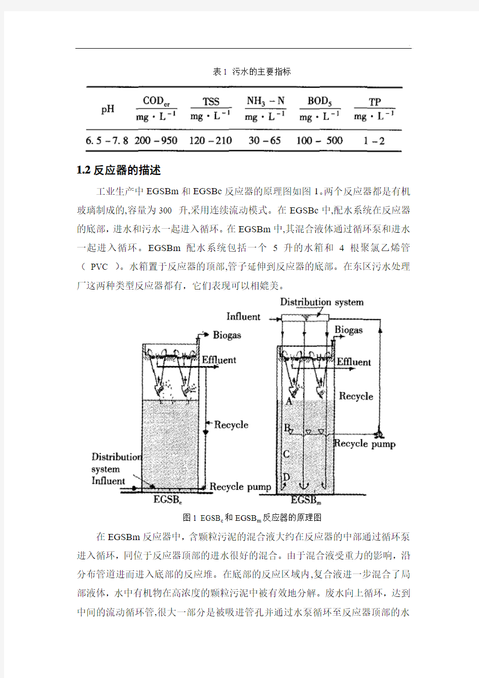
工业生产中EGSBm和EGSBc反应器的原理图如图1。两个反应器都是有机玻璃制成的,容量为300 升,采用连续流动模式。在EGSBc中,配水系统在反应器的底部,进水和污水一起进入循环。在EGSBm中,其混合液体通过循环泵和进水一起进入循环。EGSBm配水系统包括一个5升的水箱和4根聚氯乙烯管(PVC )。水箱置于反应器的顶部,管子延伸到反应器的底部。在东区污水处理厂这两种类型反应器都有,它们表现可以相媲美。
图1 EGSB c和EGSB m反应器的原理图
在EGSBm反应器中,含颗粒污泥的混合液大约在反应器的中部通过循环泵进入循环,同位于反应器顶部的进水很好的混合。由于混合液受重力的影响,沿分布管道进而进入底部的反应堆。在底部的反应区域内,复合液进一步混合了局部液体,水中有机物在高浓度的颗粒污泥中被有效地分解。废水向上循环,达到中间的流动循环管,很大一部分是被吸进管孔并通过水泵循环至反应器顶部的水
箱中,同时一小部分继续向上流动达到进一步分解。然后,向上流动的部分会进入三相分离器,在这里气体、水、颗粒状污泥会被分开。在分离后,颗粒污泥经过处理还能循环利用到上层反应室中去。
1.3实验条件
在这两个试验性反应器成功开动起来,反应达到了稳定的状态后,它们还得在常温下连续运行165 天。基于稳态条件下,总的反应过程分为十个阶段。每个阶段具体实验数据在表2中有详细说明。
表2 各反应阶段的实验数据
R:循环比例
1.4反应器的性能评价
在每个反应阶段,通过去除COD,COD filt和SS的效率来评价EGSB c和EGSB m两者的总体性能。COD filt表示经过定性滤纸后污水中的COD浓度。COD 和COD filt的浓度可以经重铬酸钾溶液检测出来,而SS的浓度是通过过滤,干燥,然后称水样本检测出来。
1.5颗粒状污泥的分析
在第4和第10个运行阶段结束后,从EGSB m反应器的四个不同反应区取颗粒污泥样本,并在图1中标明A、B、C、D。A、B、C、D四个反应区距离反应区底部分别为2.0,1.5,1.0,0.5米。从颗粒污泥中提取DNA后,16S核糖体RNA 基因的特定区域经过聚合酶链反应(PCR)被放大,进而用来克隆和排序。然后,使用变形梯度凝胶电泳(EGGB)分离聚合酶链反应(PCR)的产物。
已经分化的菌株再经过培养,使菌株数量达到所需的测量水平。
在预选的反应时间中,使用激光粒度仪(LS230,美国贝克曼库尔特)测得四个不同区域的颗粒污泥的直径分布在0.04-2000微米的范围内。
1.6水动力特性
有一种利用锂离子(Li+)的脉冲追踪仪,可以通过锂离子反应器中不同区域内停留的时间来分析水动力特性。在每一次试验中,通过脉冲注射器向进水中注入10mL浓度为10mg/L锂离子溶液,运用电感耦合等离子ICP/脂肪醇聚氧乙烯醚硫酸盐AES外加铂金埃尔默奥普玛2100等离子发射光谱仪对污水中锂离子的浓度进行周期性检测。
2 结果和讨论
2.1反应器的性能
1)上升流速(V up)的影响。对于EGSB c和EGSB m两种反应器,上升流速对污水中COD和COD filt浓度的影响在图2中有说明。结果表明在EGSB m和EGSB c两种污水中,当上升流速从5.0米/时(阶段3)到10.3米/时(阶段5),COD filt 浓度分别从94.1和97.1毫克/升(阶段1)下降为59.4和71.4毫克/升(阶段5).两种反应器污水中COD浓度和COD filt浓度变化趋势大致相同。在较高的上升流速下,通过比较两者污水中COD的浓度,显而易见,EGSB m比EGSB c具有更好的性能和恢复效果。当上升流速从2米/小时(阶段1)到10.3米/小时变化时,两种反应器中SS的浓度分别从18.5和22.2毫克/升上升为60.1和126.5毫克/升。从中我们看出在相同流速下,EGSB m比EGSB c更容易造成生物量的流失。因此,EGSB m具有较好的恢复能力是因为其高污泥浓度的保持能力。
图2 上升流速对EGSB c和EGSB m两种反应器中污水中COD和COD filt浓度的影响
2)水力停留时间的影响。水力停留时间对EGSB m和EGSB c两种反应器中污水中COD和COD filt浓度的影响可以在图3中看出来。结果显示,在EGSB m反应器中,当水力停留时间从6降为2小时时,COD和COD filt浓度分别从119.7毫克/升和94.1毫克/升(阶段1)下降为104和82.6毫克/升(阶段7)。当水力停留时间降为1小时后,EGSB m和EGSB c两者中COD和COD filt浓度都有上升趋势。但是,EGSB m有更好的基质清除效果,主要是因为它具有改进了的水循环结构。
在EGSB m和EGSB c两种反应器中,挥发性脂肪酸的平均浓度分别从28和31克/升(阶段6,水力停留时间4小时)上升为42和65克/升(阶段7,水力停留时间2小时)。这就意味着在低水力停留时间内,EGSB m比EGSB c更能有效利用挥发性脂肪酸来产生甲烷气体。
图3水力停留时间对EGSB m和EGSB c两种反应器中污水中COD和COD filt浓度的影响3)有机负载率的影响。在两种反应器中,有机负载率对COD和COD filt浓度的影响如图4。当有机负载率由7.2(阶段8)突然降为1.2千克COD/(立方米*天)(阶段9),EGSB m反应器能维持它的处理效率不变,而EGSB c则发生不
同程度的变化。当有机负荷率从1.2(阶段9)又调整到7.2千克COD/(立方米*天)时,在阶段10的初期两种反应器中COD和COD filt浓度都有明显提高。随后,EGSB m恢复到最初有机去除效率需用10天时间,而EGSB c反应器在20天后任然没能达到最初的有机物去除率水平。显而易见,EGSB m更能有效抵抗有机载荷的变化。
图4有机负载率对EGSB m和EGSB c两种反应器中污水中COD和COD filt浓度的影响总的来讲,当实验条件发生变化时,EGSB m反应器中COD,COD filt和SS 浓度比EGSB c中的浓度要低得多。即使SS浓度会随上升流速的升高而升高,但EGSB m比EGSB c的生物量流失少。而且在上升流速高达10.3米/小时时,EGSB m 反应器中污水COD含量几乎不变。
2.2颗粒污泥的分析
这幅变形梯度凝胶电泳剖面图显示的是从EGSB m反应器中提取的75天和165天颗粒污泥样本中9-12DNA片段。相比之下,我们可以从处理酸性污水的最初的接种污泥中提取第15号DNA片段。这些DNA片段分布在16S核糖核酸RNA的V3区段内,每个基因片段代表一种微生物种类。
图5颗粒污泥样本的变形梯度凝胶电泳(DGGE)剖面图比较了不同污泥样品的变形梯度凝胶电泳(DGGE)剖面图,结果表明,带1、2、3、4、9、10的接种污泥也存在于第75 天和第165 天EGSB m污泥样品中,而其他的9个频段内的接种污泥很少见。相反,在EGSB m颗粒污泥的样品中出现了一些新的频段。频段的强度随不同的运行阶段和反应区域而变化。然而,微生物物种的数量在整个反应阶段和反应区域内并没发生明显变化。由于环境的变化,譬如循环比率,水力停留时间(HRT),有机负载率(OLR)和进水质量,微生物会选择性地形成稳定的微生物群落,通过竞争来有效地降解有机污染物。
在EGSB m反应器运行1,45,76和110天,分别检测A、B、C、D四个区域内颗粒污泥直径的变化。记录数据如图6。在第1天,接种污泥的直径均匀地分布在0.8-2毫米的范围内。在第45和76天,大部分颗粒污泥的直径分布在0.6-2毫米范围内,而A和B区域也有一少部分颗粒污泥的直径分布在0.01-0.4毫米范围内。在第110天,颗粒污泥的直径逐渐地变大。从中我们看到颗粒污泥在
EGSB m中最初是分散的,随着反应条件的变化逐步聚集为厌氧微生物菌落。
图6不同反应阶段颗粒污泥直径的变化
2.3 水动力特性
当进水向上流动通过颗粒污泥床时,它将和该区域内污水混合(或分散到污水中)。因此,对于理想的塞式流动应分散考虑,如下面所表达的停留时间分布
(RTD)模型:
在公式中,D/UL表示无量纲的离散量,D表示扩散系数(平方米/小时),U表
示上升流速V up(米/小时),L代表反应器的长度(米)。对于理想的塞式流动反
应器,D/UL的值是0。相反,对于理想的连续搅拌釜式反应器(CSTR),D/UL
的值趋近无穷大。通过脉冲示踪剂(例如,Li+)的方法,示踪剂浓度会随着试
验时间在不同的水力停留时间发生变化,如图7。依据图7的结果,经过计算和
总结得出了表3中的数据,记录了在三种不同的上升流速下无关量V d和D/UL
的值。
毕业设计外文翻译资料
外文出处: 《Exploiting Software How to Break Code》By Greg Hoglund, Gary McGraw Publisher : Addison Wesley Pub Date : February 17, 2004 ISBN : 0-201-78695-8 译文标题: JDBC接口技术 译文: JDBC是一种可用于执行SQL语句的JavaAPI(ApplicationProgrammingInterface应用程序设计接口)。它由一些Java语言编写的类和界面组成。JDBC为数据库应用开发人员、数据库前台工具开发人员提供了一种标准的应用程序设计接口,使开发人员可以用纯Java语言编写完整的数据库应用程序。 一、ODBC到JDBC的发展历程 说到JDBC,很容易让人联想到另一个十分熟悉的字眼“ODBC”。它们之间有没有联系呢?如果有,那么它们之间又是怎样的关系呢? ODBC是OpenDatabaseConnectivity的英文简写。它是一种用来在相关或不相关的数据库管理系统(DBMS)中存取数据的,用C语言实现的,标准应用程序数据接口。通过ODBCAPI,应用程序可以存取保存在多种不同数据库管理系统(DBMS)中的数据,而不论每个DBMS使用了何种数据存储格式和编程接口。 1.ODBC的结构模型 ODBC的结构包括四个主要部分:应用程序接口、驱动器管理器、数据库驱动器和数据源。应用程序接口:屏蔽不同的ODBC数据库驱动器之间函数调用的差别,为用户提供统一的SQL编程接口。 驱动器管理器:为应用程序装载数据库驱动器。 数据库驱动器:实现ODBC的函数调用,提供对特定数据源的SQL请求。如果需要,数据库驱动器将修改应用程序的请求,使得请求符合相关的DBMS所支持的文法。 数据源:由用户想要存取的数据以及与它相关的操作系统、DBMS和用于访问DBMS的网络平台组成。 虽然ODBC驱动器管理器的主要目的是加载数据库驱动器,以便ODBC函数调用,但是数据库驱动器本身也执行ODBC函数调用,并与数据库相互配合。因此当应用系统发出调用与数据源进行连接时,数据库驱动器能管理通信协议。当建立起与数据源的连接时,数据库驱动器便能处理应用系统向DBMS发出的请求,对分析或发自数据源的设计进行必要的翻译,并将结果返回给应用系统。 2.JDBC的诞生 自从Java语言于1995年5月正式公布以来,Java风靡全球。出现大量的用java语言编写的程序,其中也包括数据库应用程序。由于没有一个Java语言的API,编程人员不得不在Java程序中加入C语言的ODBC函数调用。这就使很多Java的优秀特性无法充分发挥,比如平台无关性、面向对象特性等。随着越来越多的编程人员对Java语言的日益喜爱,越来越多的公司在Java程序开发上投入的精力日益增加,对java语言接口的访问数据库的API 的要求越来越强烈。也由于ODBC的有其不足之处,比如它并不容易使用,没有面向对象的特性等等,SUN公司决定开发一Java语言为接口的数据库应用程序开发接口。在JDK1.x 版本中,JDBC只是一个可选部件,到了JDK1.1公布时,SQL类包(也就是JDBCAPI)
中英文文献翻译
毕业设计(论文)外文参考文献及译文 英文题目Component-based Safety Computer of Railway Signal Interlocking System 中文题目模块化安全铁路信号计算机联锁系统 学院自动化与电气工程学院 专业自动控制 姓名葛彦宁 学号 200808746 指导教师贺清 2012年5月30日
Component-based Safety Computer of Railway Signal Interlocking System 1 Introduction Signal Interlocking System is the critical equipment which can guarantee traffic safety and enhance operational efficiency in railway transportation. For a long time, the core control computer adopts in interlocking system is the special customized high-grade safety computer, for example, the SIMIS of Siemens, the EI32 of Nippon Signal, and so on. Along with the rapid development of electronic technology, the customized safety computer is facing severe challenges, for instance, the high development costs, poor usability, weak expansibility and slow technology update. To overcome the flaws of the high-grade special customized computer, the U.S. Department of Defense has put forward the concept:we should adopt commercial standards to replace military norms and standards for meeting consumers’demand [1]. In the meantime, there are several explorations and practices about adopting open system architecture in avionics. The United Stated and Europe have do much research about utilizing cost-effective fault-tolerant computer to replace the dedicated computer in aerospace and other safety-critical fields. In recent years, it is gradually becoming a new trend that the utilization of standardized components in aerospace, industry, transportation and other safety-critical fields. 2 Railways signal interlocking system 2.1 Functions of signal interlocking system The basic function of signal interlocking system is to protect train safety by controlling signal equipments, such as switch points, signals and track units in a station, and it handles routes via a certain interlocking regulation. Since the birth of the railway transportation, signal interlocking system has gone through manual signal, mechanical signal, relay-based interlocking, and the modern computer-based Interlocking System. 2.2 Architecture of signal interlocking system Generally, the Interlocking System has a hierarchical structure. According to the function of equipments, the system can be divided to the function of equipments; the system
文献翻译英文原文
https://www.360docs.net/doc/4214321047.html,/finance/company/consumer.html Consumer finance company The consumer finance division of the SG group of France has become highly active within India. They plan to offer finance for vehicles and two-wheelers to consumers, aiming to provide close to Rs. 400 billion in India in the next few years of its operations. The SG group is also dealing in stock broking, asset management, investment banking, private banking, information technology and business processing. SG group has ventured into the rapidly growing consumer credit market in India, and have plans to construct a headquarters at Kolkata. The AIG Group has been approved by the RBI to set up a non-banking finance company (NBFC). AIG seeks to introduce its consumer finance and asset management businesses in India. AIG Capital India plans to emphasize credit cards, mortgage financing, consumer durable financing and personal loans. Leading Indian and international concerns like the HSBC, Deutsche Bank, Goldman Sachs, Barclays and HDFC Bank are also waiting to be approved by the Reserve Bank of India to initiate similar operations. AIG is presently involved in insurance and financial services in more than one hundred countries. The affiliates of the AIG Group also provide retirement and asset management services all over the world. Many international companies have been looking at NBFC business because of the growing consumer finance market. Unlike foreign banks, there are no strictures on branch openings for the NBFCs. GE Consumer Finance is a section of General Electric. It is responsible for looking after the retail finance operations. GE Consumer Finance also governs the GE Capital Asia. Outside the United States, GE Consumer Finance performs its operations under the GE Money brand. GE Consumer Finance currently offers financial services in more than fifty countries. The company deals in credit cards, personal finance, mortgages and automobile solutions. It has a client base of more than 118 million customers throughout the world
人力资源管理外文文献翻译
文献信息: 文献标题:Challenges and opportunities affecting the future of human resource management(影响人力资源管理未来的挑战和机遇) 国外作者:Dianna L. Stone,Diana L. Deadrick 文献出处:《Human Resource Management Review》, 2015, 25(2):139-145 字数统计:英文3725单词,21193字符;中文6933汉字 外文文献: Challenges and opportunities affecting the future of human resource management Abstract Today, the field of Human Resource Management (HR) is experiencing numerous pressures for change. Shifts in the economy, globalization, domestic diversity, and technology have created new demands for organizations, and propelled the field in some completely new directions. However, we believe that these challenges also create numerous opportunities for HR and organizations as a whole. Thus, the primary purposes of this article are to examine some of the challenges and opportunities that should influence the future of HR. We also consider implications for future research and practice in the field. Keywords: Future of human resource management, Globalization, Knowledge economy Diversity, Technology 1.Change from a manufacturing to a service or knowledge economy One of the major challenges influencing the future of HR processes is the change from a manufacturing to a service or knowledgebased economy. This new economy is characterized by a decline in manufacturing and a growth in service or knowledge as the core of the economic base. A service economy can be defined as a system based on buying and selling of services or providing something for others (Oxford
软件开发概念和设计方法大学毕业论文外文文献翻译及原文
毕业设计(论文)外文文献翻译 文献、资料中文题目:软件开发概念和设计方法文献、资料英文题目: 文献、资料来源: 文献、资料发表(出版)日期: 院(部): 专业: 班级: 姓名: 学号: 指导教师: 翻译日期: 2017.02.14
外文资料原文 Software Development Concepts and Design Methodologies During the 1960s, ma inframes and higher level programming languages were applied to man y problems including human resource s yste ms,reservation s yste ms, and manufacturing s yste ms. Computers and software were seen as the cure all for man y bu siness issues were some times applied blindly. S yste ms sometimes failed to solve the problem for which the y were designed for man y reasons including: ?Inability to sufficiently understand complex problems ?Not sufficiently taking into account end-u ser needs, the organizational environ ment, and performance tradeoffs ?Inability to accurately estimate development time and operational costs ?Lack of framework for consistent and regular customer communications At this time, the concept of structured programming, top-down design, stepwise refinement,and modularity e merged. Structured programming is still the most dominant approach to software engineering and is still evo lving. These failures led to the concept of "software engineering" based upon the idea that an engineering-like discipl ine could be applied to software design and develop ment. Software design is a process where the software designer applies techniques and principles to produce a conceptual model that de scribes and defines a solution to a problem. In the beginning, this des ign process has not been well structured and the model does not alwa ys accurately represent the problem of software development. However,design methodologies have been evolving to accommo date changes in technolog y coupled with our increased understanding of development processes. Whereas early desig n methods addressed specific aspects of the
英文文献翻译
中等分辨率制备分离的 快速色谱技术 W. Clark Still,* Michael K a h n , and Abhijit Mitra Departm(7nt o/ Chemistry, Columbia Uniuersity,1Veu York, Neu; York 10027 ReceiLied January 26, 1978 我们希望找到一种简单的吸附色谱技术用于有机化合物的常规净化。这种技术是适于传统的有机物大规模制备分离,该技术需使用长柱色谱法。尽管这种技术得到的效果非常好,但是其需要消耗大量的时间,并且由于频带拖尾经常出现低复原率。当分离的样本剂量大于1或者2g时,这些问题显得更加突出。近年来,几种制备系统已经进行了改进,能将分离时间减少到1-3h,并允许各成分的分辨率ΔR f≥(使用薄层色谱分析进行分析)。在这些方法中,在我们的实验室中,媒介压力色谱法1和短柱色谱法2是最成功的。最近,我们发现一种可以将分离速度大幅度提升的技术,可用于反应产物的常规提纯,我们将这种技术称为急骤色谱法。虽然这种技术的分辨率只是中等(ΔR f≥),而且构建这个系统花费非常低,并且能在10-15min内分离重量在的样本。4 急骤色谱法是以空气压力驱动的混合介质压力以及短柱色谱法为基础,专门针对快速分离,介质压力以及短柱色谱已经进行了优化。优化实验是在一组标准条件5下进行的,优化实验使用苯甲醇作为样本,放在一个20mm*5in.的硅胶柱60内,使用Tracor 970紫外检测器监测圆柱的输出。分辨率通过持续时间(r)和峰宽(w,w/2)的比率进行测定的(Figure 1),结果如图2-4所示,图2-4分别放映分辨率随着硅胶颗粒大小、洗脱液流速和样本大小的变化。
客户关系管理外文文献翻译(2017)
XXX学院 毕业设计(论文)外文资料翻译 学院:计算机与软件工程学院 专业:计算机科学技术(软件工程方向) 姓名: 学号: 外文出处:GoyKakus.THE RESEARCH OFCUSTOMER RELATIONSHIP MANAGEMENT STRATEGY [J]. International Journal of Management Research & Review, 2017, 1(9): 624-635. 附件: 1.外文资料翻译译文;2.外文原文。 注:请将该封面与附件装订成册。
附件1:外文资料翻译译文 客户关系管理战略研究 Goy Kakus 摘要 客户关系管理解决方案,通过为你提供客户业务数据来帮助你提供客户想要的服务或产品,提供更好的客户服务、交叉销售和更有效的销售,达成交易,保留现有客户并更好地理解你的客户是谁。本文探讨了客户关系管理模型在获得、保持与发展策略方面的优势。然而,我们对其定义和意义还存在一些困惑。本文通过考察关系营销和其他学科方面的相关文献,解释了客户关系管理的概念基础,从而对客户关系管理的知识作出了贡献。 关键词:客户关系管理模型, 客户关系管理的博弈改变者与关键策略 引言 CRM 是客户关系管理的简称。它的特征在于公司与客户的沟通,无论是销售还是服务相关的。客户关系管理这一术语经常用来解释企业客户关系,客户关系管理系统也以同样的方式被用来处理商业联系, 赢得客户,达成合同和赢得销售。 客户关系管理通常被考虑作为一个业务策略,从而使企业能够: *了解客户 *通过更好的客户体验留住客户 *吸引新客户 *赢得新客户和达成合同 *提高盈利 *减少客户管理成本 *通过服务台等工具软件,电子邮件组织者和不同类型的企业应用程序,企业业务经常寻求个性化的在线体验。 设计精良的客户关系管理包括以下特征: 1.客户关系管理是一种以顾客为中心并以客户投入为基础的服务响应,一对一的解决客户的必需品, 买家和卖家服务中心直接在线互动,帮助客户解决他
本科毕业设计方案外文翻译范本
I / 11 本科毕业设计外文翻译 <2018届) 论文题目基于WEB 的J2EE 的信息系统的方法研究 作者姓名[单击此处输入姓名] 指导教师[单击此处输入姓名] 学科(专业 > 所在学院计算机科学与技术学院 提交日期[时间 ]
基于WEB的J2EE的信息系统的方法研究 摘要:本文介绍基于工程的Java开发框架背后的概念,并介绍它如何用于IT 工程开发。因为有许多相同设计和开发工作在不同的方式下重复,而且并不总是符合最佳实践,所以许多开发框架建立了。我们已经定义了共同关注的问题和应用模式,代表有效解决办法的工具。开发框架提供:<1)从用户界面到数据集成的应用程序开发堆栈;<2)一个架构,基本环境及他们的相关技术,这些技术用来使用其他一些框架。架构定义了一个开发方法,其目的是协助客户开发工程。 关键词:J2EE 框架WEB开发 一、引言 软件工具包用来进行复杂的空间动态系统的非线性分析越来越多地使用基于Web的网络平台,以实现他们的用户界面,科学分析,分布仿真结果和科学家之间的信息交流。对于许多应用系统基于Web访问的非线性分析模拟软件成为一个重要组成部分。网络硬件和软件方面的密集技术变革[1]提供了比过去更多的自由选择机会[2]。因此,WEB平台的合理选择和发展对整个地区的非线性分析及其众多的应用程序具有越来越重要的意义。现阶段的WEB发展的特点是出现了大量的开源框架。框架将Web开发提到一个更高的水平,使基本功能的重复使用成为可能和从而提高了开发的生产力。 在某些情况下,开源框架没有提供常见问题的一个解决方案。出于这个原因,开发在开源框架的基础上建立自己的工程发展框架。本文旨在描述是一个基于Java的框架,该框架利用了开源框架并有助于开发基于Web的应用。通过分析现有的开源框架,本文提出了新的架构,基本环境及他们用来提高和利用其他一些框架的相关技术。架构定义了自己开发方法,其目的是协助客户开发和事例工程。 应用程序设计应该关注在工程中的重复利用。即使有独特的功能要求,也
英文文献及中文翻译
毕业设计说明书 英文文献及中文翻译 学院:专 2011年6月 电子与计算机科学技术软件工程
https://www.360docs.net/doc/4214321047.html, Overview https://www.360docs.net/doc/4214321047.html, is a unified Web development model that includes the services necessary for you to build enterprise-class Web applications with a minimum of https://www.360docs.net/doc/4214321047.html, is part of https://www.360docs.net/doc/4214321047.html, Framework,and when coding https://www.360docs.net/doc/4214321047.html, applications you have access to classes in https://www.360docs.net/doc/4214321047.html, Framework.You can code your applications in any language compatible with the common language runtime(CLR), including Microsoft Visual Basic and C#.These languages enable you to develop https://www.360docs.net/doc/4214321047.html, applications that benefit from the common language runtime,type safety, inheritance,and so on. If you want to try https://www.360docs.net/doc/4214321047.html,,you can install Visual Web Developer Express using the Microsoft Web Platform Installer,which is a free tool that makes it simple to download,install,and service components of the Microsoft Web Platform.These components include Visual Web Developer Express,Internet Information Services (IIS),SQL Server Express,and https://www.360docs.net/doc/4214321047.html, Framework.All of these are tools that you use to create https://www.360docs.net/doc/4214321047.html, Web applications.You can also use the Microsoft Web Platform Installer to install open-source https://www.360docs.net/doc/4214321047.html, and PHP Web applications. Visual Web Developer Visual Web Developer is a full-featured development environment for creating https://www.360docs.net/doc/4214321047.html, Web applications.Visual Web Developer provides an ideal environment in which to build Web sites and then publish them to a hosting https://www.360docs.net/doc/4214321047.html,ing the development tools in Visual Web Developer,you can develop https://www.360docs.net/doc/4214321047.html, Web pages on your own computer.Visual Web Developer includes a local Web server that provides all the features you need to test and debug https://www.360docs.net/doc/4214321047.html, Web pages,without requiring Internet Information Services(IIS)to be installed. Visual Web Developer provides an ideal environment in which to build Web sites and then publish them to a hosting https://www.360docs.net/doc/4214321047.html,ing the development tools in Visual Web Developer,you can develop https://www.360docs.net/doc/4214321047.html, Web pages on your own computer.
仪表板外文文献翻译、中英文翻译、外文翻译
Dashboard From Wikipedia, the free encyclopedia This article is about a control panel placed in the front of the car. For other uses, see Dashboard (disambiguation). The dashboard of a Bentley Continental GTC car A dashboard (also called dash, instrument panel (IP), or fascia) is a control panel located directly ahead of a vehicle's driver, displaying instrumentation and controls for the vehicle's operation. Contents 1.Etymology 2.Dashboard features 3.Padding and safety 4.Fashion in instrumentation 5.See also 6.References Etymology Horse-drawn carriage dashboard Originally, the word dashboard applied to a barrier of wood or leather fixed at the front of a horse-drawn carriage or sleigh to protect the driver from mud or other debris "dashed up" (thrown up) by the horses' hooves.[1] Commonly these boards did not perform any additional function other than providing a convenient handhold for ascending into the driver's seat, or a small clip with which to secure the reins when not in use. When the first "horseless carriages" were constructed in the late 19th century, with engines mounted beneath the driver such as the Daimler Stahlradwagen, the simple dashboard was retained to protect occupants from debris thrown up by the cars' front wheels. However, as car design evolved to position the motor in front of the driver, the dashboard became a panel that protected vehicle occupants from the heat and oil of the engine. With gradually increasing mechanical complexity, this panel formed a convenient location for the placement of gauges and minor controls, and from this evolved the modern instrument panel,
工商管理专业外文文献翻译
Project Budget Monitor and Control Author:Yin Guo-li Nationality:American Derivation:Management Science and Engineering.Montreal: Mar 20, 2010 . With the marketing competitiveness growing, it is more and more critical in budget control of each project. This paper discusses that in the construction phase, how can a project manager be successful in budget control. There are many methods discussed in this paper, it reveals that to be successful, the project manager must concern all this methods. 1. INTRODUCTION The survey shows that most projects encounter cost over-runs (Williams Ackermann, Eden, 2002,pl92). According to Wright (1997)'s research, a good rule of thumb is to add a minimum of 50% to the first estimate of the budget (Gardiner and Stewart, 1998, p251). It indicates that project is very complex and full of challenge. Many unexpected issues will lead the project cost over-runs. Therefore, many technologies and methods are developed for successful monitoring and control to lead the project to success. In this article, we will discuss in the construction phase, how can a project manager to be successful budget control. 2. THE CONCEPT AND THE PURPOSE OF PROJECT CONTROL AND MONITOR Erel and Raz (2000) state that the project control cycle consists of measuring the status of the project, comparing to the plan, analysis of the deviations, and implementing any appropriate corrective actions. When a project reach the construction phase, monitor and control is critical to deliver the project success. Project monitoring exists to establish the need to take corrective action, whilst there is still time to take action. Through monitoring the activities, the project team can analyze the deviations and decide what to do and actually do it. The purpose of monitor and control is to support the implementation of corrective actions, ensure projects stay on target or get project back on target once it has gone off target。
本科毕业设计外文翻译
Section 3 Design philosophy, design method and earth pressures 3.1 Design philosophy 3.1.1 General The design of earth retaining structures requires consideration of the interaction between the ground and the structure. It requires the performance of two sets of calculations: 1)a set of equilibrium calculations to determine the overall proportions and the geometry of the structure necessary to achieve equilibrium under the relevant earth pressures and forces; 2)structural design calculations to determine the size and properties of thestructural sections necessary to resist the bending moments and shear forces determined from the equilibrium calculations. Both sets of calculations are carried out for specific design situations (see 3.2.2) in accordance with the principles of limit state design. The selected design situations should be sufficiently Severe and varied so as to encompass all reasonable conditions which can be foreseen during the period of construction and the life of the retaining wall. 3.1.2 Limit state design This code of practice adopts the philosophy of limit state design. This philosophy does not impose upon the designer any special requirements as to the manner in which the safety and stability of the retaining wall may be achieved, whether by overall factors of safety, or partial factors of safety, or by other measures. Limit states (see 1.3.13) are classified into: a) ultimate limit states (see 3.1.3); b) serviceability limit states (see 3.1.4). Typical ultimate limit states are depicted in figure 3. Rupture states which are reached before collapse occurs are, for simplicity, also classified and