flange_chart(法兰规格型号)
Page 1 of 12 Look to as "The Source".
API SPEC 6A, 16A, 17D AND MSS
FLANGE GASKET, BOLT AND TORQUE REFERENCE CHART
TRADEMARK
REG. U.S. PATENT OFFICE
Terms of Use and Copyright ? 2005 WOODCO USA
WOODCO USA provides Web Site Tools for identification, estimating, and reference only. Do not use this information for manufacturing or inspection. Users of these tools should not use them as a substitute for professional engineering advice. Anyone making use of the information presented does so at his own risk and assumes any and all liability resulting from such use.
FOR FURTHER INFORMATION, OR TO LEARN MORE ABOUT WOODCO USA PRODUCTS AND SERVICES,
CONTACT:
WOODCO USA
P.O. Box 1261
Houston, Texas 77251-1261
Phone: 713-672-9491
U.S. and Canada: 1-800-496-6326
Fax: 713-672-8768
https://www.360docs.net/doc/4617890994.html,
sales@https://www.360docs.net/doc/4617890994.html,
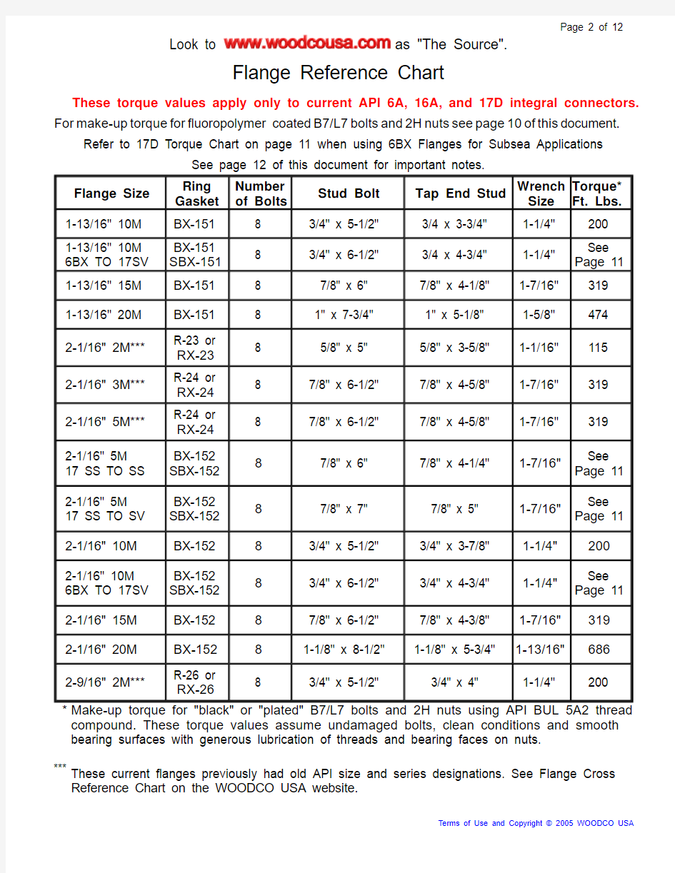
These torque values apply only to current API 6A, 16A, and 17D integral connectors. For make-up torque for fluoropolymer coated B7/L7bolts and2H nuts see page10of this document.
Refer to 17D Torque Chart on page 11 when using 6BX Flanges for Subsea Applications
See page 12 of this document for important notes.
Flange Size
Ring
Gasket
Number
of Bolts
Stud Bolt Tap End Stud
Wrench
Size
Torque*
Ft. Lbs.
1-13/16" 10M BX-151 8 3/4" x 5-1/2" 3/4 x 3-3/4" 1-1/4" 200
1-13/16" 10M 6BX TO 17SV
BX-151
SBX-151
8 3/4" x 6-1/2" 3/4 x 4-3/4" 1-1/4"
See
Page 11
1-13/16" 15M BX-151 8 7/8" x 6" 7/8" x 4-1/8" 1-7/16" 319 1-13/16" 20M BX-151 8 1" x 7-3/4" 1" x 5-1/8" 1-5/8" 474
2-1/16" 2M***R-23 or
RX-23
8 5/8" x 5" 5/8" x 3-5/8" 1-1/16" 115
2-1/16" 3M***R-24 or
RX-24
8 7/8" x 6-1/2" 7/8" x 4-5/8" 1-7/16" 319
2-1/16" 5M***R-24 or
RX-24
8 7/8" x 6-1/2" 7/8" x 4-5/8" 1-7/16" 319
2-1/16" 5M 17 SS TO SS
BX-152
SBX-152
87/8" x 6" 7/8" x 4-1/4" 1-7/16"
See
Page 11
2-1/16" 5M 17 SS TO SV
BX-152
SBX-152
87/8" x 7" 7/8" x 5" 1-7/16"
See
Page 11
2-1/16" 10M BX-152 83/4" x 5-1/2" 3/4" x 3-7/8" 1-1/4"200
2-1/16" 10M 6BX TO 17SV
BX-152
SBX-152
83/4" x 6-1/2" 3/4" x 4-3/4" 1-1/4"
See
Page 11
2-1/16" 15M BX-152 87/8" x 6-1/2" 7/8" x 4-3/8" 1-7/16"319 2-1/16" 20M BX-15281-1/8" x 8-1/2" 1-1/8" x 5-3/4" 1-13/16"686
2-9/16" 2M***R-26 or
RX-26
8 3/4" x 5-1/2" 3/4" x 4" 1-1/4" 200
* Make-up torque for "black" or "plated" B7/L7 bolts and 2H nuts using API BUL 5A2 thread compound. These torque values assume undamaged bolts, clean conditions and smooth bearing surfaces with generous lubrication of threads and bearing faces on nuts.
***These current flanges previously had old API size and series designations. See Flange Cross Reference Chart on the WOODCO USA website.
Terms of Use and Copyright ? 2005 WOODCO USA
These torque values apply only to current API 6A, 16A, and 17D integral connectors. For make-up torque for fluoropolymer coated B7/L7bolts and2H nuts see page10of this document.
Refer to 17D Torque Chart on page 11 when using 6BX Flanges for Subsea Applications
See page 12 of this document for important notes.
Flange Size
Ring
Gasket
Number
of Bolts
Stud Bolt Tap End Stud
Wrench
Size
Torque*
Ft. Lbs.
2-9/16" 3M***R-27 or
RX-27
8 1" x 7" 1" x 5-1/8" 1-5/8" 474
2-9/16" 5M***R-27 or
RX-27
8 1" x 7" 1" x 5-1/8" 1-5/8" 474
2-9/16" 5M 17 SS TO SS
BX-153
SBX-153
8 1" x 6-1/2" 1" x 4-5/8" 1-5/8"
See
Page 11
2-9/16" 5M 17 SS TO SV
BX-153
SBX-153
8 1" x 7-1/4" 1" x 5-3/8" 1-5/8"
See
Page 11
2-9/16" 10M BX-153 8 7/8" x 6-1/2" 7/8" x 4-3/8" 1-7/16" 319
2-9/16" 10M 6BX TO 17SV
BX-153
SBX-153
8 7/8" x 7-1/4" 7/8" x 5" 1-7/16"
See
Page 11
2-9/16" 15M BX-153 8 1" x 7-1/4" 1" x 4-7/8" 1-5/8" 474 2-9/16" 20M BX-153 8 1-1/4" x 9-1/2" 1-1/4" x 6-1/4" 2" 953
3-1/8" 2M***R-31 or
RX-31
83/4" x 5-3/4" 3/4" x 4-1/8" 1-1/4"200
3-1/8 3M***R-31 or
RX-31
87/8" x 6-1/2" 7/8" x 4-5/8" 1-7/16"319
3-1/8" 5M***R-35 or
RX-35
8 1-1/8" x 7-3/4" 1-1/8" x 5-5/8" 1-13/16" 686
3-1/8" 5M
17 SS TO SS
BX-154
SBX-154
8 1-1/8" x 7-1/4" 1-1/8" x 5-1/8" 1-13/16"
See
Page 11
3-1/8" 5M 17 SS TO SV
BX-154
SBX-154
8 1-1/8" x 8" 1-1/8" x 5-3/4" 1-13/16"
See
Page 11
* Make-up torque for "black" or "plated" B7/L7 bolts and 2H nuts using API BUL 5A2 thread compound. These torque values assume undamaged bolts, clean conditions and smooth bearing surfaces with generous lubrication of threads and bearing faces on nuts.
***These current flanges previously had old API size and series designations. See Flange Cross Reference Chart on the WOODCO USA website.
Terms of Use and Copyright ? 2005 WOODCO USA
These torque values apply only to current API 6A, 16A, and 17D integral connectors. For make-up torque for fluoropolymer coated B7/L7bolts and2H nuts see page10of this document.
Refer to 17D Torque Chart on page 11 when using 6BX Flanges for Subsea Applications
See page 12 of this document for important notes.
Flange Size
Ring
Gasket
Number
of Bolts
Stud Bolt Tap End Stud
Wrench
Size
Torque*
Ft. Lbs.
3-1/16" 10M BX-154 8 1" x 7-1/4" 1" x 5" 1-5/8" 474
3-1/16" 10M 6BX TO 17SV
BX-154
SBX-154
8 1" x 8"1" x 5-3/4" 1-5/8"
See
Page 11
3-1/16" 15M BX-154 8 1-1/8" x 8" 1-1/8" x 5-1/2" 1-13/16" 686 3-1/16" 20M BX-154 8 1-3/8" x 10-1/4" 1-3/8" x 6-3/4" 2-3/16" 1,281
4-1/16" 2M***R-37 or
RX-37
8 7/8" x 6-1/2" 7/8" x 4-5/8" 1-7/16" 319
4-1/16" 3M***R-37 or
RX-37
8 1-1/8" x 7-1/2" 1-1/8" x 5-1/2" 1-13/16" 686
4-1/16" 5M***R-39 or
RX-39
8 1-1/4" x 8-1/2" 1-1/4" x 6-1/8" 2" 953
4-1/16" 5M 17 SS TO SS
BX-155
SBX-155
8 1-1/4" x 8" 1-1/4" x 5-5/8" 2"
See
Page 11
4-1/16" 5M 17 SS TO SV
BX-155
SBX-155
8 1-1/4" x 8-3/4" 1-1/4" x 6-1/4" 2"
See
Page 11
4-1/16" 10M BX-155 8 1-1/8" x 8-1/2" 1-1/8" x 5-3/4" 1-13/16" 686
4-1/16" 10M 6BX TO 17SV
BX-155
SBX-155
8 1-1/8" x 9-1/2" 1-1/8" x 6-5/8" 1-13/16"
See
Page 11
4-1/16" 15M BX-155 8 1-3/8" x 9-3/4" 1-3/8" x 6-1/2" 2-3/16" 1,281 * Make-up torque for "black" or "plated" B7/L7 bolts and 2H nuts using API BUL 5A2 thread compound. These torque values assume undamaged bolts, clean conditions and smooth bearing surfaces with generous lubrication of threads and bearing faces on nuts.
***These current flanges previously had old API size and series designations. See Flange Cross Reference Chart on the WOODCO USA website.
Terms of Use and Copyright ? 2005 WOODCO USA
These torque values apply only to current API 6A, 16A, and 17D integral connectors. For make-up torque for fluoropolymer coated B7/L7bolts and2H nuts see page10of this document.
Refer to 17D Torque Chart on page 11 when using 6BX Flanges for Subsea Applications
See page 12 of this document for important notes.
Flange Size
Ring
Gasket
Number
of Bolts
Stud Bolt Tap End Stud
Wrench
Size
Torque*
Ft. Lbs.
4-1/16" 20M BX-155 8 1-3/4" x 12-1/2" 1-3/4" x 8-3/8" 2-3/4" 2,696
5-1/8" 2M***R-41 or
RX-41
8 1" x 7-1/4" 1" x 5-1/4" 1-5/8" 474
5-1/8" 3M***R-41 or
RX-41
8 1-1/4" x 8-1/4" 1-1/4" x 6" 2" 953
5-1/8" 5M***R-44 or
RX-44
8 1-1/2" x 10-1/2" 1-1/2" x 7-3/8" 2-3/8" 1,677
5-1/8" 5M
17 SS TO SS
BX-169
SBX-169
8 1-1/2" x 10" 1-1/2" x 6-7/8" 2-3/8"
See
Page 11
5-1/8" 5M
17 SS TO SV
BX-169
SBX-169
8 1-1/2" x 11" 1-1/2" x 7-3/4" 2-3/8"
See
Page 11
5-1/8" 10M BX-169 12 1-1/8" x 9-1/4" 1-1/8" x 6" 1-13/16" 686
5-1/8" 10M
6BX TO 17SV
BX-169
SBX-169
12 1-1/8" x 10-1/4" 1-1/8" x 7" 1-13/16"
See
Page 11
5-1/8" 15M BX-169 12 1-1/2" x 11-1/2" 1-1/2" x 7-5/8" 2-3/8" 1,677
7-1/16" 2M***R-45 or
RX-45
12 1" x 7-1/2" 1" x 5-3/8" 1-5/8" 474
7-1/16" 3M***R-45 or
RX-45
12 1-1/8" x 8-1/2" 1-1/8" x 5-7/8" 1-13/16" 686
7-1/16" 5M***R-46 or
RX-46
12 1-3/8" x 11-1/4" 1-3/8" x 7-1/2" 2-3/16" 1,281
* Make-up torque for "black" or "plated" B7/L7 bolts and 2H nuts using API BUL 5A2 thread compound. These torque values assume undamaged bolts, clean conditions and smooth bearing surfaces with generous lubrication of threads and bearing faces on nuts.
***These current flanges previously had old API size and series designations. See Flange Cross Reference Chart on the WOODCO USA website.
Terms of Use and Copyright ? 2005 WOODCO USA
These torque values apply only to current API 6A, 16A, and 17D integral connectors. For make-up torque for fluoropolymer coated B7/L7bolts and2H nuts see page10of this document.
Refer to 17D Torque Chart on page 11 when using 6BX Flanges for Subsea Applications
See page 12 of this document for important notes.
Flange Size
Ring
Gasket
Number
of Bolts
Stud Bolt Tap End Stud
Wrench
Size
Torque*
Ft. Lbs.
7-1/16" 5M 17 SS TO SS
BX-156
SBX-156
12 1-3/8" x 10-3/4" 1-3/8" x 7" 2-3/16"
See
Page 11
7-1/16" 5M 17 SS TO SV
BX-156
SBX-156
12 1-3/8" x 11-3/4" 1-3/8" x 8-1/8" 2-3/16"
See
Page 11
7-1/16" 10M BX-156 12 1-1/2" x 11-3/4" 1-1/2" x 7-3/4" 2-3/8" 1,677
7-1/16" 10M 6BX TO 17SV
BX-156
SBX-156
12 1-1/2" x 13" 1-1/2" x 9" 2-3/8"
See
Page 11
7-1/16" 15M BX-156 16 1-1/2" x 13" 1-1/2" x 8-3/8" 2-3/8" 1,677 7-1/16" 20M BX-156 16 2" x 17-3/4" 2" x 11-1/8" 3-1/8" 4,061
9" 2M***R-49 or
RX-49
12 1-1/8" x 8-1/2" 1-1/8" x 5-7/8" 1-13/16" 686
9" 3M***R-49 or
RX-49
12 1-3/8" x 9-1/2" 1-3/8" x 6-3/4" 2-3/16" 1,281
9" 5M***R-50 or
RX-50
12 1-5/8" x 12-1/2" 1-5/8" x 8-1/2" 2-9/16" 2,146
9" 5M
17 SS TO SS
BX-157
SBX-157
12 1-5/8" x 12" 1-5/8" x 8" 2-9/16"
See
Page 11
9" 5M
17 SS TO SV
BX-157
SBX-157
12 1-5/8" x 13-1/4" 1-5/8" x 9-1/8" 2-9/16"
See
Page 11
9" 10M BX-157 16 1-1/2" x 13-1/2" 1-1/2" x 8-1/2" 2-3/8" 1,677 * Make-up torque for "black" or "plated" B7/L7 bolts and 2H nuts using API BUL 5A2 thread compound. These torque values assume undamaged bolts, clean conditions and smooth bearing surfaces with generous lubrication of threads and bearing faces on nuts.
***These current flanges previously had old API size and series designations. See Flange Cross Reference Chart on the WOODCO USA website.
Terms of Use and Copyright ? 2005 WOODCO USA
These torque values apply only to current API 6A, 16A, and 17D integral connectors. For make-up torque for fluoropolymer coated B7/L7bolts and2H nuts see page10of this document.
Refer to 17D Torque Chart on page 11 when using 6BX Flanges for Subsea Applications
See page 12 of this document for important notes.
Flange Size
Ring
Gasket
Number
of Bolts
Stud Bolt Tap End Stud
Wrench
Size
Torque*
Ft. Lbs.
9" 10M
6BX TO 17SV
BX-157
SBX-157
16 1-1/2" x 15" 1-1/2" x 10-1/8" 2-3/8"
See
Page 11
9" 15M BX-157 16 1-7/8" x 16" 1-7/8" x 10-1/8" 2-15/16" 3,332 9" 20M BX-157 16 2-1/2" x 21-3/4 2-1/2" x 13-3/4" 3-7/8" 8,030
11" 2M***R-53 or
RX-53
16 1-1/4" x 9-1/4" 1-1/4" x 6-1/2" 2" 953
11" 3M***R-53 or
RX-53
16 1-3/8" x 10" 1-3/8" x 7" 2-3/16" 1,281
11" 5M***R-54 or
RX-54
12 1-7/8" x 14-1/4" 1-7/8" x 9-5/8" 2-15/16" 3,332
11" 5M
17 SS TO SS
BX-158
SBX-158
12 1-7/8" x 13-3/4" 1-7/8" x 9-1/8" 2-15/16"
See
Page 11
11" 5M
17 SS TO SV
BX-158
SBX-158
12 1-7/8" x 15-1/4" 1-7/8" x 10-1/2" 2-15/16"
See
Page 11
11" 10M BX-158 16 1-3/4" x 15-1/4" 1-3/4" x 9-3/4" 2-3/4" 2,696
11" 10M
6BX TO 17SV
BX-158
SBX-158
16 1-3/4" x 17" 1-3/4" x 11-1/2" 2-3/4"
See
Page 11
11" 15M BX-158 20 2" x 19-1/2" 2" x 12" 3-1/8" 4,061
11" 20M BX-158 16 2-3/4" x 23-3/4" 2-3/4" x 15" 4-1/4" 9,712 * Make-up torque for "black" or "plated" B7/L7 bolts and 2H nuts using API BUL 5A2 thread compound. These torque values assume undamaged bolts, clean conditions and smooth bearing surfaces with generous lubrication of threads and bearing faces on nuts.
***These current flanges previously had old API size and series designations. See Flange Cross Reference Chart on the WOODCO USA website.
Terms of Use and Copyright ? 2005 WOODCO USA
These torque values apply only to current API 6A, 16A, and 17D integral connectors. For make-up torque for fluoropolymer coated B7/L7bolts and2H nuts see page10of this document.
Refer to 17D Torque Chart on page 11 when using 6BX Flanges for Subsea Applications
See page 12 of this document for important notes.
Flange Size
Ring
Gasket
Number
of Bolts
Stud Bolt Tap End Stud
Wrench
Size
Torque*
Ft. Lbs.
13-5/8" 2M***R-57 or
RX-57
20 1-1/4" x 9-1/2" 1-1/4" x 6-5/8" 2" 726**
13-5/8 3M***R-57 or
RX-57
20 1-3/8" x 10-3/4" 1-3/8" x 7-3/8" 2-3/16" 976**
13-5/8" 5M BX-160 16 1-5/8" x 12-3/4" 1-5/8" x 8-3/8" 2-9/16" 2,146 13-5/8" 10M BX-159 20 1-7/8" x 17-3/4" 1-7/8" x 11" 2-15/16" 3,332
13-5/8" 10M 6BX TO 17SV
BX-159
SBX-159
20 1-7/8" x 19-3/4" 1-7/8" x 13-1/8" 2-15/16"
See
Page 11
13-5/8" 15M BX-159 20 2-1/4" x 21-1/4" 2-1/4" x 13-1/4" 3-1/2" 5,822 13-5/8" 20M BX-159 20 3" x 29-3/4" 3" x 18-1/8" 4-5/8" 12,654
16-3/4" 2M***R-65 or
RX-65
20 1-1/2" x 10-3/4" 1-1/2" x 7-1/2" 2-3/8" 1,278**
16-3/4" 3M***R-66 or
RX-66
20 1-5/8" x 12-1/4" 1-5/8" x 8-3/8" 2-9/16" 2,146
16-3/4" 5M BX-162 16 1-7/8" x 14-3/4" 1-7/8" x 9-1/2" 2-15/16" 3,332 16-3/4" 10M BX-162 24 1-7/8" x 17-3/4" 1-7/8" x 11" 2-15/16" 3,332 18-3/4" 5M BX-163 20 2" x 17-3/4" 2" x 11-1/4" 3-1/8" 4,061 18-3/4" 10M BX-164 24 2-1/4" x 22-3/4" 2-1/4" x 14" 3-1/2" 5,822 18-3/4" 15M BX-164 20 3" x 26-3/4" 3" x 16-3/4" 4-5/8" 12,654 * Make-up torque for "black" or "plated" B7/L7 bolts and 2H nuts using API BUL 5A2 thread compound. These torque values assume undamaged bolts, clean conditions and smooth bearing surfaces with generous lubrication of threads and bearing faces on nuts.
**These API Spec. 6A flanges have stress limits that necessitate lower than normal torque values for bolts used in these flanges.
***These current flanges previously had old API size and series designations. See Flange Cross Reference Chart on the WOODCO USA website.
Terms of Use and Copyright ? 2005 WOODCO USA
These torque values apply only to current API 6A, 16A, and 17D integral connectors. For make-up torque for fluoropolymer coated B7/L7bolts and2H nuts see page10of this document.
Refer to 17D Torque Chart on page 11 when using 6BX Flanges for Subsea Applications
See page 12 of this document for important notes.
Flange Size
Ring
Gasket
Number
of Bolts
Stud Bolt Tap End Stud
Wrench
Size
Torque*
Ft. Lbs.
20-3/4" 3M***R-74 or
RX-74
20 2" x 15" 2" x 10-1/8" 3-1/8" 4,061
21-1/4" 2M***R-73 or
RX-73
24 1-5/8" x 12-1/4" 1-5/8" x 8-3/8" 2-9/16" 1,635**
21-1/4" 5M BX-165 24 2" x 19" 2" x 11-3/4" 3-1/8" 4,061 21-1/4" 10M BX-166 24 2-1/2" x 24-3/4" 2-1/2" x 15-1/8" 3-7/8" 8,030 26-3/4" 2M BX-167 20 1-3/4" x 14-1/4" 1-3/4" x 9-1/8" 2-3/4" 2,696 26-3/4" 3M BX-168 24 2" x 17-1/2" 2" x 11" 3-1/8" 4,061 30" 300 MSS1R-9528 1-3/4" x 13-1/2" 1-3/4" x 9-1/8" 2-3/4" 2,696 30" 600 MSS1R-9528 2" x 15-3/4" 2" x 10-1/2" 3-1/8" 4,061
30" 2M BX-303 32 1-5/8" x 14-1/2" 1-5/8" x 9-1/4" 2-9/16" 2,146 30" 3M BX-303 32 1-7/8" x 17-3/4" 1-7/8" x 11" 2-15/16" 3,332 * Make-up torque for "black" or "plated" B7/L7 bolts and 2H nuts using API BUL 5A2 thread compound. These torque values assume undamaged bolts, clean conditions and smooth bearing surfaces with generous lubrication of threads and bearing faces on nuts.
**These API Spec. 6A flanges have stress limits that necessitate lower than normal torque values for bolts used in these flanges.
***These current flanges previously had old API size and series designations. See Flange Cross Reference Chart on the WOODCO USA website.
1Not API
Terms of Use and Copyright ? 2005 WOODCO USA
Make-up torque for fluoropolymer coated B7/L7 bolts and 2H nuts.
These torque values apply only to current API 6A, 16A, and MSS integral connectors. These torques assume undamaged bolts, clean conditions and smooth bearing surfaces.
Stud
5/8"3/4"7/8"1"1-1/8"1-1/4" *1-3/8" *1-1/2" *1-5/8" *1-3/4"1-7/8" Diameter
Torque
681181882794015537399621,2261,5341,890 Ft. Lbs.
Stud
2"2-1/4"2-1/2"2-5/8"2-3/4"3"3-1/4"3-3/4"3-7/8"4" Diameter
Torque
2.2973,2764,5004,7165,4247,0478,96513,78215,20816,730 Ft. Lbs.
*Certain API Spec. 6A flanges have stress limits that necessitate lower than normal torque values for bolts used in these flanges. Use the chart below for these flanges.
.
Flange
13-5/8" 2M13-5/8" 3M 16-3/4" 2M 21-1/4" 2M
Size
Stud
1-1/4"1-3/8"1-1/2" 1-5/8"
Diameter
Torque
421563733934
Ft. Lbs.
Terms of Use and Copyright ? 2005 WOODCO USA
API Spec17D Recommended Torque For Flange Bolts and Nuts
With Fluoropolymer Coating
Used for Subsea Applications
See Caution Below
Bolt Size Hex Nut
Size
Across
Flats
Minimum 67%
Yield Stress *
Maximum 70%
Yield Stress*
Bolt
Tension
lbf
Make up
Torque
ft lbs
Bolt
Tension
lbf
Make up
Torque
ft lbs
3/4 - 10 UNC1-1/423,53016024,538167
7/8 - 9 UNC1-7/1632,48325333,937264
1 - 8 UN1-5/842,61437644,522393
1-1/8 - 8 UN1-13/1655,60853958,098564
1-1/4 - 8 UN270,33074473,478777
1-3/8 - 8 UN2-3/1686,77799490,6621,038
1-1/2 - 8 UN2-3/8104,9511,294109,6501,352
1-5/8 - 8 UN2-9/16124,8521,649130,4421,723
1-3/4 - 8 UN2-3/4146,4802,063153,0382,155
1-7/8 - 8 UN2-15/16169,8332,541177,4382,654
2 - 8 UN3-1/8194,9143,087203,6423,225
2-1/4 - 8 UN3-1/2250,2564,402261,4614,599
2-1/2 - 8 UN3-7/8312,5046,044326,4976,315
2-3/4 - 8 UN**4-1/4345,3107,284360,7727,611
*Torque ft lbs calculated to give % of yield tension stress for ASTM A-193 B7 or
ASTM A-302 L7 bolts using ASTM A 194 GR. 2H nuts.
**Calculated based on reduced yield strength of 95,000 psi.
CAUTION: API Spec 17D requires flange connection bolt tightness
(tension stress in the bolt) equal to 67% to 70% of the specified
minimum yield strength of L7/B7 bolts. When using some lubricants
and/or anti-corrosion coatings on bolts, tightening bolts consistent
with the torque table shown above may in fact produce tension
closer to the actual yield strength of the bolts. Operators should use
an alternate method to measure tension in the bolts to confirm the applicability of this table.
Terms of Use and Copyright ? 2005 WOODCO USA
Flange Reference Chart
Important Notes
Obsolete, Discontinued or Withdrawn flanges not included in this chart also use B7/L7 connecting bolts. For bolt sizes and torque values for these flanges, see individual flange pages in the Flange Slide Rule Program on the https://www.360docs.net/doc/4617890994.html, web site.
Flanges with "R" ring grooves can connect and seal with either R or RX ring gaskets. RX gaskets increase the stand-off between flanges, and studs shown on this chart have sufficient length to accommodate RX gaskets in these connections. In some cases equipment design may restrict clearance and shorter studs will increase convenience. For information on these shorter stud lengths, see AWHEM document TR9501 at https://www.360docs.net/doc/4617890994.html,/docs.htm. To compare the difference in stand-off see https://www.360docs.net/doc/4617890994.html,/standoff.htm#Select
Caution: The difference in stand-off between R and RX gaskets can cause alignment problems on close coupled manifolding or pressure controlling loops. Assembly designers specify component dimensions which allow for the difference in stand-off between flanges when choosing either R or RX gaskets. When operators perform maintenance that involves disassembly, trouble free reassembly requires using gaskets the same as the gaskets originally chosen.
Ring gaskets marked SRX or SBX have identical measurements to RX and BX ring gaskets with the the same number designation, and they will fit the same corresponding connectors. API Spec 17D intends SBX gaskets to seal all 17D SS and SV flanges and all 6BX flanges used for subsea applications. API Spec 17D intends SRX gaskets to seal only 5000 psi segmented flanges, not listed above. The "S" indicates these gaskets have vent holes to allow reliable connector make-up underwater (subsea). API Spec 17D requires that manufacturers use only corrosion resistant alloy as the material for these gaskets.
For more information about ring gaskets, see Web Site Tools, and click on Ring Gasket Handling and Inspection Before Assembly.
For more information about ring gasket sealing, see Web Site Tools, and click on Field Appraisal of Ring Grooves.
For more information about flange connection make-up, see Web Site Tools, and click on Flange Make-up, Stand-off and Drift.
Terms of Use and Copyright ? 2006 WOODCO USA
Terms of Use
Welcome to https://www.360docs.net/doc/4617890994.html,, the official website of WOODCO USA (“WOODCO”). https://www.360docs.net/doc/4617890994.html, provides services to you subject to the following conditions. If you visit https://www.360docs.net/doc/4617890994.html,, you accept these conditions. Please read them carefully. In addition, when you use any current or future https://www.360docs.net/doc/4617890994.html, service or download WOODCO USA software, you also agree to comply with any of these conditions that may apply to such service or software use.
1.WOODCO USA may change, add, or remove portions of its website at any time. WOODCO USA
also may impose limits on certain features and services or restrict access to all or any part of its website without notice or liability.
2.WOODCO USA intends its website (the “Content”) for your personal use only.
3.All materials published on the WOODCO USA website have copyright protection pursuant to U.S.
and international copyright laws. You may not modify, publish, transmit, participate in the transfer or sale of, reproduce (except as provided in Paragraph 4 below), create new works from, distribute, perform, display, or in any way exploit any of the Content in whole or in part. You shall abide by all additional copyright notices, information, and other restrictions associated with any of the Content.
4.You may download or copy the Content and other downloadable items forming parts of the Content
for personal use only, provided that you maintain all copyright and other notices contained therein.
You may not copy or store any Content for other than personal use without prior written permission from an officer of WOODCO USA.
5.WOODCO USA does not assume liability for any errors or omissions in the Content, or in the
transmission or delivery of all or any part thereof, or for any damages arising there from. You acknowledge sole responsibility (sole risk) for any reliance you may have in the Content or actions you may take relying upon any of the Content. WOODCO USA makes every effort to assure the accuracy of the Content, but, WOODCO USA MAKES THE CONTENT AVAILABLE TO YOU ON AN "AS IT APPEARS" BASIS, WITHOUT WARRANTIES OF ANY KIND, EITHER EXPRESS OR IMPLIED, INCLUDING, WITHOUT LIMITATION, ANY WARRANTIES OF TITLE OR IMPLIED WARRANTIES OF MERCHANTABILITY OR FITNESS FOR A PARTICULAR PURPOSE. YOU HEREBY ACKNOWLEDGE THAT YOU USE THE CONTENT AT YOUR SOLE RISK.
6.You shall have no rights to any of the proprietary rights associated with any of the Content.
7.WOODCO USA may, in its sole discretion, terminate or suspend access to all or part of the Content
for any reason, including without limitation, breach or assignment of this Agreement.
8.This Agreement originates in Houston, Texas and any interpretation and/or enforcement shall
comply with Texas law. Any action to enforce this agreement shall occur in, and only in, the federal or state courts located in Harris County, Texas.
9.Privacy - Please review our Privacy Policy, which also governs your visit to https://www.360docs.net/doc/4617890994.html,, to
understand our practices.
10.Please direct all questions to: sitemaster@https://www.360docs.net/doc/4617890994.html,
Copyright Notice 1999 - 2005, WOODCO USA.
WOODCO USA will enforce all rights under copyright law, regarding all photographs, graphics, written materials or other content appearing on this website, the legally protected property of WOODCO USA. WOODCO USA prohibits reproduction or re-use of any kind, other than that described in “Terms of Use”above, without written permission from an officer of WOODCO USA. Submit all requests for re-use of copyrighted materials in writing to: sitemaster@https://www.360docs.net/doc/4617890994.html,
常用法兰规格尺寸表
常用法兰规格尺寸表(国标) 发布时间:2010.07.13 新闻来源:法兰-法兰盘-法兰毛坯-弯头-三通-无缝钢管-聊城荣丰法兰制造厂浏览次数: 593 常用法兰规格尺寸表(国标) GB9119,2—88GB9119,2—88 in 法兰公称 通径 10kg=1.0MPa 公称通径 16kg=1.6MPa 法兰外 径 螺栓孔 距 螺栓直 径 螺栓孔数法兰厚度法兰外径螺栓孔距螺栓直径螺栓孔数法兰厚度 3/8 DN10 50 60 14 4 14 DN10 90 60 14 4 14 1/2 DN15 59 65 14 4 14 DN15 95 65 14 4 14 3/4 DN20 105 75 14 4 16 DN20 105 75 14 4 16 1 DN25 115 85 14 4 16 DN25 115 85 14 4 16 11/4DN32 140 100 18 4 18 DN32 140 100 18 4 18 11/2DN40 150 110 18 4 18 DN40 150 110 18 4 18 2 DN50 165 125 18 4 20 DN50 165 125 18 4 20 21/2DN65 185 145 18 4 20 DN65 185 145 18 4 20 3 DN80 200 160 18 8 20 DN80 200 160 18 8 20 31/2DN100 220 180 18 8 22 DN100 220 180 18 8 22 4 DN12 5 250 210 18 8 22 DN125 250 210 18 8 22 5 DN150 285 240 22 8 24 DN150 285 240 22 8 24 6 DN200 340 295 22 8 24 DN200 340 295 22 8 26 8 DN250 395 350 22 12 26 DN250 405 355 26 12 29 10 DN300 445 400 22 12 28 DN300 460 410 26 12 32 12 DN350 505 460 22 16 30 DN350 520 470 26 16 35 14 DN400 565 515 26 16 32 DN400 580 525 30 16 38 16 DN450 615 565 26 20 35 DN450 640 585 30 20 42 18 DN500 670 620 26 20 38 DN500 715 650 33 20 46 20 DN600 780 725 26 20 42 DN600 840 770 36 20 52
金属软管接头简介
金属软管接头 金属软管接头是现代工业管路中的一种高品质的柔性管道。它主要由波纹管、网套和接头组成。它的内管是具有螺旋形或环形的薄壁不锈钢波纹管,波纹管外层的网套,是由不锈钢丝或钢带按一定的参数编织而成。 目录 1介绍 2型号 介绍 金属软管接头是现代工业管路中的一种高品质的柔性管道。它主要由 MOLLET金属软管接头 波纹管、网套和接头组成。它的内管是具有螺旋形或环形的薄壁不锈钢波纹管,波纹管外层的网套,是由不锈钢丝或钢带按一定的参数编织而成。软管两端的接头或法兰是与客户管道的接头或法兰相配的。软管的波纹管是由极薄壁的无缝或众焊不锈钢钢管经过高精度塑性加工成形的。由于波纹管轮廓的弹性特性决定了软管具有良好的柔软性和抗疲劳性,使它很容易吸收各种运动变形的循环载荷,尤其在管路系统中有补偿大位移量的能力。介质可视化(介可视),过程自动化。
金属接头采用锌合金材料压铸而成,表面镀锌、磨沙或镀铬;结构紧密,强度高。钢管与金属软管连接可靠,外表美观; 此金属接头为卡套式,用来将金属软管连接于不带螺纹的钢管之上; 适配金属软管:JS型、JSH型、JSB型、JSHG型; 适配钢管:薄钢电线管、黑、白铁管(水、煤气管); 选用DKJ卡套式金属接头时请注意连接钢管软管的规格、尺寸。 金属软管接头 DGJ接头 金属软管接头 结构及特性: DGJ自固式金属软管接头,能将无螺纹的钢管或无螺纹的设备出线口与软管连接,省却套丝工序; 金属接头采用锌合金材料压铸而成,表面镀锌、磨沙、或镀铬;结构紧密,强度高。钢管与金属软管连接可靠,外表美观; 此金属接头为自固式,用来将金属软管连接于无螺纹的钢管或无螺纹的设备出线口之上; 适配金属软管:JS型、JSH型、JSB型、JSHG型; 适配钢管:薄钢电线管、黑、白铁管(水、煤气管); 选用DGJ自固式金属软管接头时请注意连接钢管软管的规格、尺寸。
法兰盘规格尺寸
HG/T 20592 40-16 RF A=M20*1.5: 40-16是公称直径DN40的法兰,公称压力16公斤也就是1.6MPa,RF指密封面为突面,A=M20X1.5指该法兰上所配的螺栓规格。 GB9119,2—88GB9119,2—88 in 公称 通径 10kg=1.0MPa 公称 通径 16kg=1.6MPa 法 兰 外 径 螺栓 孔距 螺 栓 直 径 螺栓 孔数 法兰 厚度 法兰 外径 螺栓 孔距 螺栓 直径 螺栓 孔数 法兰厚度 3/8 DN10 506014414DN10 906014414 1/2 DN15 596514414DN15 956514414 3/4 DN20 1057514416DN20 1057514416 1 DN25 1158514416DN25 1158514416 11/4DN32 14010018418DN32 14010018418 11/2DN40 150********DN40 150******** 2 DN50 16512518420DN50 16512518420 21/2DN65 185********DN65 185******** 3 DN80 20016018820DN80 20016018820 31/2DN10 22018018822DN100 22018018822 4 DN12 5 25021018822DN125 25021018822 5 DN15 28524022824DN150 28524022824 6 DN20 34029522824DN200 34029522826 8 DN25 395350221226DN250 405355261229 10 DN30 445400221228DN300 460410261232 12 DN35 505460221630DN350 520470261635
穿线金属软管金属软管内外径对照表
穿线金属软管参数 内径[mm] 外径 [mm] 公差 +/- [mm] 拉伸状 态的重 量 +/-10% [Kg/m] 最小弯 曲半径 [mm] 最小径 向载荷 [N] 最小抗拉 强度 [N] 4 6 0.1 0.034 1 5 800 320 5 7 0.1 0.039 17 835 340 6 8 0.2 0.044 19 875 360 7 9 0.2 0.049 20 930 380 8 10 0.2 0.056 22 975 400 9 11 0.2 0.063 25 1020 450 10 13 0.2 0.100 30 1060 500 11 14 0.2 0.110 31 1095 550 12 15 0.2 0.120 32 1140 600 13 16 0.2 0.130 33 1175 650 14 17 0.2 0.140 35 1215 700 15 18 0.2 0.150 37 1250 720 16 19 0.2 0.160 40 1290 760 17 20 0.2 0.170 45 1330 800 18 21 0.2 0.180 42 1470 890 19 23 0.3 0.212 40 1510 840 20 24 0.3 0.223 42 1545 890 21 25 0.3 0.235 45 1580 920 22 26 0.3 0.247 48 1620 940 23 27 0.3 0.258 52 1655 960 24 28 0.3 0.269 55 1690 980 25 29 0.3 0.280 58 1735 1000 26 30 0.3 0.292 60 1770 1020
金属软管,塑料软管连接件
金属软管、塑料软管连接件JSF-DPJ端接式包塑软管接头软管接头包塑金属软管接头
JSF-DPJ端接式包塑软管接头采用0#锌合金(铝合金)压铸(浇铸)而成,表面镀锌或镀铬。JSF-DPJ金属软管接头结构紧密,无气孔,强度高,与金属软管连接可靠,外表美观大方; JSF-DPJ金属接头是上海京生电器JB/GQ0552-83执行标准中D96-4A,D95-5金属接头的延伸产品; JSF-DPJ包塑软管接头为端接式,用来将京生金属软管连接于箱体上的直线连接件; JSF-DPJ适配金属软管:JSF-JS型、JSF-JSH型、JSF-JSB型、JSF-JSHG型; 推荐使用英制管螺纹或公制螺纹;其他德标PG或美标NPT螺纹等可来电京生电器公司快速订做。 配套金属软管规格JSF-DPJ外螺纹金属软管接头提供螺纹范围公制英制英制螺纹G公制螺纹M美标螺纹NPT德标螺纹PG φ6 1/16″G1/4″M14×1.5 1/4″NPT PG7 φ8 1/8″G3/8″M16×1.5 3/8″NPT PG9 φ10 1/4″G3/8″M16×1.5 3/8″NPT PG9 φ12 3/8″ G3/8″ M20×1.5 3/8″NPT PG11 PG13.5
φ15(16)1/2″ G1/2″ M20×1.5 M24×1.5 1/2″NP T PG13.5 PG16 φ20(19)3/4″ G3/4″ M27×2.0 M30×2.0 3/4″NPT PG21 φ25 1″ G1″ M33×2.0 M36×2.0 1″NPT PG29 φ32 1-1/4″ G1-1/4″ M42×2.0 M48×2.0 1-1/4″NPT PG29 φ38(40)1-1/2″ G1-1/2″ M48×2.0 M60×2.0 1-1/2″NPT PG36 PG42 φ51(50)2″ G2″ M60×2.0 M70×2.0 2″NPT PG48 φ64(70)2-1/2″ G2-1/2″ M76×2.0 2-1/2″NPT φ75(80)3″ G3″ M88×2.0 3″NPT φ100 4″ G4″ M114×2.0 4″NPT φ125 5″ G5″ M140×2.0 5″NPT φ150 6″ G6″ M164×2.0 6″NPT φ2008″ G8″ M188×2.0 8″NPT 注:特殊规格、型号,特殊螺纹可来电订做。 三柱卡套接头卡套式管接头卡套式软管接头JSF-DKJ
金属软管规格
金属软管规格 总则( Z% I8 N E4 h" B9 \/ {3 d' R0 H2 f 1.1 范围 1.1.1 本规定对金属软管在设计、材料选用、检验/试验、标注、涂漆和运输准备等方面提出了详细的要求。% P: @2 r7 z3 P2 j0 w' J, e 1.1.2 本规定内容若与1.2条款中引用的文件有矛盾时,应按照较严格的规定执行。* k" V/ n" p$ l 1.1.3 在金属软管的询价/订货过程中,本规定应作为技术文件,和金属软管数据表(金属软管规格书)一并提交给供应商。6 r# T) o5 `6 ^% C- U 注:金属软管数据表包括:位号、尺寸、数量和详细要求。 1.1.4 本规定适用于SEI(买方)对金属软管的设计、采购工作。1 h3 s) x0 z! E: @: `6 V) F+ _ 1.2 规范性引用文件 下列文件中的条款通过本规定的引用而成为本规定的条款,其最新版本适用于本规定。1)ASME 规范和标准 B31.3 工艺配管 B1.1 统一英制螺纹# `( N/ h1 ]. c# \0 w6 ` B1.20.1 管螺纹(一般用途)) T2 A' G/ _1 ] B16.5 钢制管法兰和法兰管件0 O) ?) B$ _; P1 B B16.25 对焊端部 B46.1 表面粗糙度" j! r5 F% P Q! U" R 2)MSS 标准 SP-25 阀门、管件、法兰和活接头用标准标记系统 3)ASTM 标准 4)工程的相关规定6 o8 n' { y6 v; s7 \( K9 k 2 金属软管的设计 2.1 金属软管的工艺条件5 /8 F( u2 U# j4 /$ f6 z 金属软管的工艺数据,详见金属软管规格书。 2.2 金属软管的结构 1)金属软管的结构,详见金属软管规格书。 2)金属软管的弯曲半径至少为公称直径的10倍。7 G- K( T( f; l% r6 J6 Z 2.3 金属软管的端部连接' T# D1 X# k- ^0 _: @ 1)金属软管的端部连接要求,详见金属软管规格书;& t3 b; v& M# Z2 d. J) w# S3 r7 d 2)金属软管的端部连接应执行的标准如下:$ [ M4 U$ Z; ]$ f4 m8 / 法兰连接: ASME B16.5 (24”及以下) 承插焊连接: ASME B16.11 螺纹连接: ASME B1.20.1 3)密封面加工粗糙度; y1 Y6 y& M2 H; i5 z2 } 通常,法兰的密封面加工粗糙度为125μin~250μin(3.2微米~6.3微米)。( c5 U, /7 ?$ f8 w! r 2.4 制造要求0 u( l# B% V, ~ 1)金属软管的焊接、预热和焊后热处理应符合ASME B31.3的要求。9 L& E* /. ~! W7 D,
金属软管及管接头的规格
按JG/T3053-1998标准
JSF-JSB平包塑软管[平包塑金属软管]
卡套式金属软管接头 DKJ. 螺纹厚壁钢管(水、煤、气管)薄壁钢管(电线管)公制英制
公称英称外径×壁厚英称公称外径×壁厚 17.00×2.25 φ12(13)3/8″15.87×1.60 #15 5/8″ 3/8″ #12 #15 1/2″ 1/2″φ15(21.25×2.75 16) 19.05×1.80 #20 3/4″#20 3/4″)φ20( 3/4″25.40×1.80 #25 1″ 26.75×2.75 19#25 1″ 1″ #32 1-1/4″31.75×1.80 33.50×3.25 φ25 #32 1/4″1- 1-42.25×3.25 1/4″φ32 #40 38.10×1.80 1/2″G1- #40 φ38(40) G1-#50 1/2″ 2″ 50.80×2.00 1-48.00×3.50 1/2″ φ51( 2-1/2″ 63.50×2.50 50#50 ) #70 2″ 60.00×3.50 2″ φ64(70)#70 2-#80 3″ 76.20×3.20 1/2″ 1/2″2-75.50×3.75 φ75(80) #80 88.50×4.00 3″ 3″ 4″φ100 #100 114.0×4.00 4″ 140.0×4.50 φ125 5″ #125 5″ φ150 6″ #150 6″ 165.0×4.50 φ2008″ 8″ #200 注:特殊规格、型号,特殊螺纹可来电订做。 自固式管接头DGJ 配套金属软管规格DGJ卡套金属接头对应钢管尺寸 螺纹厚壁钢管(水、煤、气管)薄壁钢管(电线管) 公制英制 公称英称外径×壁厚外径×壁厚英称公称17.00×2.25 5/8″ 15.87×1.60 φ12(13#15 ) 3/8″ 3/8″ #12 #15 3/4″ 19.05×1.80 )16 1/2″ 21.25×2.75 1/2″φ15(#20 #20 3/4″)19φ20( 26.75×2.75 3/4″ 25.40×1.80 1″#25
法兰盘规格尺寸
GB9119,2—88GB9119,2—88 in 公称 通径 10kg=1.0MPa 公称 通径 16kg=1.6MPa 法 兰 外 径 螺栓 孔距 螺 栓 直 径 螺栓 孔数 法兰 厚度 法兰 外径 螺栓 孔距 螺栓 直径 螺栓 孔数 法兰厚度 3/8 DN10 506014414DN10 906014414 1/2 DN15 596514414DN15 956514414 3/4 DN20 1057514416DN20 1057514416 1 DN25 1158514416DN25 1158514416 11/4DN32 14010018418DN32 14010018418 11/2DN40 150********DN40 150******** 2 DN50 16512518420DN50 16512518420 21/2DN65 185********DN65 185******** 3 DN80 20016018820DN80 20016018820 31/2DN10 22018018822DN100 22018018822 4 DN12 5 25021018822DN125 25021018822 5 DN15 28524022824DN150 28524022824 6 DN20 34029522824DN200 34029522826 8 DN25 395350221226DN250 405355261229 10 DN30 445400221228DN300 460410261232 12 DN35 505460221630DN350 520470261635 14 DN40 565515261632DN400 580525301638 16 DN45615565262035DN450 640585302042
金属软管的接头的区别和选型
金属软管的接头的区别和选型金属软管的NPT、PT、G、公制螺纹的含义和区别 金属软管的螺纹接头包含很多类型,很多人对此并不太十分明白,现就对这些螺纹符合作一些解释与说明: NPT,PT,G 都是管螺纹 NPT 是 National (American) Pipe Thread 的缩写, NPT 是美制锥管螺纹,用于密封。属于美国标准的 60 度锥管螺纹,用于北美地区.国家标准可查阅GB/T12716-1991 PT 是 Pipe Thread 的缩写,是 55 度密封圆锥管螺纹,属惠氏螺纹家族,多用于欧洲及英联邦国家.常用于水及煤气管行业,锥度规定为 1:16.国家标准可查阅 GB/T7306-2000 G 是 55 度非螺纹密封管螺纹,属惠氏螺纹家族.标记为 G 代表圆柱螺纹.国家标准可查阅 GB/T7307-2001 。 G 就是管螺纹的统称(Guan),55,60度的划分属于功能性的,俗称管圆。即螺纹由一圆柱面加工而成。 公制螺纹用螺距来表示,美英制螺纹用每英寸内的螺纹牙数来表示,这是它们最大的区别。 公制螺纹是60度等边牙型,英制螺纹是等腰55度牙型,美制螺纹60度。 公制螺纹用公制单位,美英制螺纹用英制单位。 管螺纹主要用来进行管道的连接,其内外螺纹的配合紧密,有直管与锥管两种。公称直径是指所连接的管道直径,显然螺纹直径比公称直径大。 金属软管的选型五要素 (1)尺寸软管公称通径,选用接头型式(主要有法兰联接、螺纹连接、快速接头连接)及金属软管的尺寸,软管长度。 (2)压力根据软管实际工作压力,再查询波纹金属软管的公称通径与压力表,决定是否使用不锈钢网套类型的金属软管。 (3)介质软管中所输送的介质的化学属性,按软管材质耐腐蚀性能,决定软管各零件的材质。 (4)温度软管内介质的工作温度及范围;软管工作时的环境温度。高温时,
金属软管接头规格型号
金属软管接头规格型号 金属软管两端接头 金属软管接头主要包括螺纹连接、法兰连接、快速接头连接等型式。 不锈钢网套是金属编织软管安装在压力管道中的主要承压件,同时对金属软管起保护作用,根据管道中的压力大小及应用场所,可选择一层或多层的不锈钢丝或钢带进行是由按一定的参数编织而成,形成耐高压金属软管。金属软管主要零件的材料采用奥氏体不锈钢,从而保证了金属软管优良的耐温性和耐腐蚀性,金属软管的工作温度范围极大,为―196~600℃,在实际使用过程中,金属软管材料的选择应根据管道介质的腐蚀性选择相应的不锈钢牌号,即可保证金属软管的耐腐蚀性。
软管接头类别 金属软管的NPT、PT、G、公制螺纹的含义和区别 金属软管的螺纹接头包含很多类型,很多人对此并不太十分明白,现就对这些螺纹符合作一些解释与说明: NPT,PT,G 都是管螺纹 NPT 是 National (American) Pipe Thread 的缩写, NPT 是美制锥管螺纹,用于密封。属于美国标准的 60 度锥管螺纹,用于北美地区.国家标准可查阅 GB/T12716-1991 PT 是 Pipe Thread 的缩写,是 55 度密封圆锥管螺纹,属惠氏螺纹家族,多用于欧洲及英联邦国家.常用于水及煤气管行业,锥度规定为 1:16.国家标准可查阅 GB/T7306-2000 G 是 55 度非螺纹密封管螺纹,属惠氏螺纹家族.标记为 G 代表圆柱螺纹.国家标准可查阅 GB/T7307-2001 。 G 就是管螺纹的统称(Guan),55,60度的划分属于功能性的,俗称管圆。即螺纹由一圆柱面加工而成。 公制螺纹用螺距来表示,美英制螺纹用每英寸内的螺纹牙数来表示,这是它们最大的区别。 公制螺纹是60度等边牙型,英制螺纹是等腰55度牙型,美制螺纹60度。 公制螺纹用公制单位,美英制螺纹用英制单位。 管螺纹主要用来进行管道的连接,其内外螺纹的配合紧密,有直管与锥管两种。公称直径是指所连接的管道直径,显然螺纹直径比公称直径大。 金属软管选型五要素 (1)尺寸软管公称通径,选用接头型式(主要有法兰联接、螺纹连接、快速接头连接)及金属软管的尺寸,软管长度。
金属软管规格不锈钢PU钢丝软管规格
金属软管规格不锈钢PU钢丝软管规格 产品系列:金属穿线软管请将鼠标移至产品图上查看清晰大图 鼠标没有反应请单击此处 相关介绍 软管提供规格5mm-25mm的不锈钢软管,包括金属软管、不锈钢软管、不锈钢金属软管,包塑金属软管、包塑不锈钢软管、不锈钢穿线软管、金属穿线软管、不锈钢护套软管、不锈钢波纹软管、金属波纹软管等,并提供配套的金属软管接头、金属软管价格及详细的金属软管资讯等服务。同丰软管生产的不锈钢软管均按国家标准、EN标准、DIN标准、JIS标准等金属软管标准生产。 不锈钢软管采用的主要材料:采用SUS301不锈钢和SUS304不锈钢、铜,从而保证了不锈钢软管优良的柔软性、耐蚀性、耐高温等性能,在实际使用过程中,不锈钢软管材料选择应根据产品性能选择相应的不锈钢牌号和结构。 不锈钢软管能保护电缆或管道避免受到电火花、热金属屑和化学污染的损害。独特的制造技术确保产品的稳定性和柔顺性。特殊预制材料的使用可屏蔽电磁波。同丰金属软管两种基本类型:简单的啮合结构P3 spuarelock 型;双层扣接结构P4 interlock型的不锈钢软管。 同丰不锈钢软管九大优点: 1、不锈钢软管节距之间灵活; 2、不锈钢软管有较好的伸缩性,无阻塞和僵硬; 3、不锈钢软管重量轻、口径一致性好; 4、不锈钢软管柔软性、重复弯曲性、挠性好; 5、不锈钢软管耐腐蚀性、耐高温性好;
6、不锈钢软管防鼠咬、耐磨损好,防止内部电线受到磨损; 7、不锈钢软管耐弯折、抗拉性能、抗侧压性强; 8、不锈钢软管柔软顺滑、易于穿线安装定位; 9、PVC不锈钢软管防水性能好。 不锈钢软管产品用途:用作各种设备信号线、传输电线电缆、光纤光缆保护。适用四大类产品: 1、铠装光缆、精密光学尺、光学测量仪器、医疗仪器、机器设备用的电线保护管; 2、适用公用电话机、远传水表、门磁报警器等其它需要对电线进行安全防护的设备; 3、各种细小电线的保护管; 4、各种计算机、机器人等等的网络线保护用管。 注:特殊规格的软管如单扣不锈钢软管外径25mm以上,双扣不锈钢软管18mm以上的软管订购。更多https://www.360docs.net/doc/4617890994.html,
常用法兰规格尺寸表
常用法兰规格尺寸表(国标、美标、日标) GB9119,2—88 GB9119,2—88 in 公称通径 10kg=1.0MPa 公称通径 16kg=1.6MPa 法兰外径 螺栓孔距 螺栓直径 螺栓孔数 法兰厚度 法兰外径 螺栓孔距 螺栓直径 螺栓 孔数 法兰厚度 3/8 DN10 50 60 14 4 14 DN10 90 60 14 4 14 ㎡㎏ 1/2 DN15 59 65 14 4 14 DN15 95 65 14 4 14 3/4 DN20 105 75 14 4 16 DN20 105 75 14 4 16 1 DN25 115 85 14 4 16 DN2 5 115 85 14 4 1 6 11 /4 DN32 140 100 18 4 18 DN32 140 100 18 4 18 11 /2 DN40 150 110 18 4 18 DN40 150 110 18 4 18 2 DN50 165 125 18 4 20 DN50 165 125 18 4 20 21/2 DN65 185 145 18 4 20 DN65 185 145 18 4 20 3 DN80 200 160 18 8 20 DN80 200 160 18 8 20 31/2 DN100 220 180 18 8 22 DN100 220 180 18 8 22 4 DN125 250 210 18 8 22 DN125 250 210 18 8 22 5 DN150 285 240 22 8 24 DN150 285 240 22 8 24 6 DN200 340 295 22 8 24 DN200 340 295 22 8 26 8 DN250 395 350 22 12 26 DN250 405 355 26 12 29 10 DN300 445 400 22 12 28 DN300 460 410 26 12 32 12 DN350 505 460 22 16 30 DN350 520 470 26 16 35 14 DN400 565 515 26 16 32 DN400 580 525 30 16 38 16 DN450 615 565 26 20 35 DN450 640 585 30 20 42 18 DN500 670 620 26 20 38 DN500 715 650 33 20 46 20 DN600 780 725 26 20 42 DN600 840 770 36 20 52 24 JIS 标准 JIS 标准 JIS 标准 in 公称通径 10kg=1.0MPa 公称通 径 16kg=1.6MPa 公称通径 20kg=2.0MPa 法兰外径 螺栓孔距 螺栓直径 螺栓孔数 法兰厚度 法兰外径 螺栓孔距 螺栓直径 螺栓 孔数 法兰厚度 法兰外径 螺栓孔距 螺栓直径 螺 栓孔 数 法兰厚度 3/8 DN10 DN10 DN10 1/2 DN15 DN15 DN15 3/4 DN20 DN20 DN20 1 DN25 DN25 DN25 11 /4 DN32 DN32 DN32 11/2 DN40 140 105 19 4 16 DN40 140 105 19 4 16 DN40 140 105 19 4 18 2 DN50 155 120 19 4 16 DN50 155 120 19 8 16 DN50 155 120 19 8 18 21 /2 DN65 175 140 19 4 18 DN65 175 140 19 8 18 DN65 175 140 19 8 20 3 DN80 185 150 19 8 18 DN80 200 , 160 22 8 20 DN80 200 160 23 8 22 31/2 DN90 195 160 19 8 18 DN90 210 170 22 8 20 DN90 210 170 23 8 24
金属软管敷设长度
金属软管敷设长度 [ 2008-9-10 14:36:00 | By: mucktruck ] 接线盒(箱)的安装应平整牢固,与钢管连接紧密,钢管进入灯头盒,开关盒(箱)时,明配管应用锁紧迫母固定,露出丝扣为2~4扣.暗配管可用焊接固定,管口露出盒(箱)应小于5mm. 7,因设计修改,暗敷管需延伸至某用电点时,须用电线管连接,不能使用金属软管. 8,明配管连接部分用6铜电线接跨接,管子预穿铁丝,管口装上塑料护套,然后堵上木枳. 9,电线管穿线后严禁在管线上施焊及作电焊接地通路,避免损坏导线绝缘层,造成线路短路. 10,钢管穿线每一回路导线之间和对地的绝缘电阻阻值不得小于1MW. 11,穿线时应按规范分色编码.这项工作十分重要,必须从编制材料计划就开始抓起,领料,穿线,接线时应重复核对. 12,灯具,器具安装 ①灯具,开关,插座的安装应平整,牢固,清洁整齐,高度一致,位置正确,开关应切断相线.暗开关和暗插座安装的垂直度及相邻高低差应符合要求(按标高尺寸在走廊始终端粒粉线,另统一门框边至线盒的距离,可在15~20cm范围选定). ②所有金属吸顶架盒,灯具均应采用保安接零,保安接零与接地装置共用,接地电阻不大于1Ω. ③插座地线要可靠,相线零线,地线安装应符合规范要求. ④灯具安装应配合装修,筒灯金属外壳可靠接地,不得在天花内裸露电线,严禁裸露驳接线口.灯具线路若在天花内有驳口时应设接线盒. 针对此项通病,首先在采购上应加以控制,各种规格的专用接地线卡必须与所配线管相配,工地收货时应仔细检验,接地跨接导线,电线管统一采用截面为4平方毫米的铜线,严禁采用熔焊连接的方式进行跨接. 9,线管敷设排列不整齐美观,支吊架,卡码设置不合理,固定点间距不均匀,管卡与终端,弯头中点,电器器具或(箱,盘,柜)边缘的距离超过500mm. 对策: 电线管施工时,必须对各回路进行统筹安排,具体操作时必须排列整齐,横平竖直,
法兰规格表
法兰规格表|常用法兰规格尺寸表(国标) 法兰规格表|常用法兰规格尺寸表(国标)无缝合金管合金钢管 GB9119,2—88 GB9119,2—88 in 公称通径 10kg=1.0MPa 公称通径 16kg=1.6法兰外 径 螺栓孔 距 螺栓直 径 螺栓孔数法兰厚度法兰外径螺栓孔距螺栓直 3/8 DN10 50 60 14 4 14 DN10 90 60 14 1/2 DN15 59 65 14 4 14 DN15 95 65 14 3/4 DN20 105 75 14 4 16 DN20 105 75 14 1 DN25 115 85 14 4 16 DN25 115 85 14 11/4 DN32 140 100 18 4 18 DN32 140 100 18 11/2 DN40 150 110 18 4 18 DN40 150 110 18 2 DN50 165 125 18 4 20 DN50 165 125 18 21/2 DN65 185 145 18 4 20 DN65 185 145 18 3 DN80 200 160 18 8 20 DN80 200 160 18 31/2 DN100 220 180 18 8 22 DN100 220 180 18 4 DN12 5 250 210 18 8 22 DN125 250 210 18 5 DN150 285 240 22 8 24 DN150 285 240 22 6 DN200 340 295 22 8 24 DN200 340 295 22 8 DN250 395 350 22 12 26 DN250 405 355 26 10 DN300 445 400 22 12 28 DN300 460 410 26 12 DN350 505 460 22 16 30 DN350 520 470 26 14 DN400 565 515 26 16 32 DN400 580 525 30 16 DN450 615 565 26 20 35 DN450 640 585 30 18 DN500 670 620 26 20 38 DN500 715 650 33 20 DN600 780 725 26 20 42 DN600 840 770 36
法兰盘规格尺寸
法兰盘规格尺寸 Prepared on 24 November 2020
GB9119,2—88GB9119,2—88 in 公称 通径 10kg= 公称通 径 16kg= 法 兰 外 径 螺栓孔 距 螺栓直 径 螺栓 孔数 法兰 厚度 法兰外径螺栓孔距螺栓直径螺栓孔数法兰厚度 3/8DN10506014414DN10906014414 1/2DN155********DN159******** 3/4DN201057514416DN201057514416 1DN251158514416DN251158514416 11/4DN3214010018418DN3214010018418 11/2DN4015011018418DN4015011018418 2DN5016512518420DN5016512518420 21/2DN6518514518420DN6518514518420 3DN8020016018820DN8020016018820 31/2DN10022018018822DN10 22018018822 4DN12525021018822DN12 5 25021018822 5DN15028524022824DN15 28524022824 6DN20034029522824DN20 34029522826 8DN250395350221226DN25 405355261229 10DN300445400221 2 28 DN30 460410261232 12DN350505*********DN35 520470261635 14DN400565515261632DN40 580525301638 16DN450615565262035DN45 640585302042 18DN500670620262038DN50 715650332046 20DN600780725262042DN60 840770362052 JIS标准JIS标准
法兰用螺栓尺寸对照表
6)法兰用螺栓尺寸对照表(DIMENSIONS OF FLANGE BOLTS) For Class150LB Flanges For Class300LB Flanges Size No. of Bolts Dia of Bolts Length of Bolt No.of Bolts Dia of Bolt Length of Bolt NPS ISO RF RJ ISO RF RJ 1/241/2M1460--41/2M146575 3/441/2M1465--45/8M167590 141/2M14658045/8M168090 11/441/2M14708545/8M168595 11/241/2M14708543/4M2090100 245/8M16859585/8M1690100 21/245/8M169010083/4M20100115 345/8M169010083/4M20110120 31/285/8M169010083/4M20110125 485/8M169010083/4M20110130 583/4M209511083/4M20120135 683/4M20100115123/4M20125140 883/4M20110120127/8M24140155 10127/8M24115130161M24155170 12127/8M241201351611/8M30170185 14121M271301502011/8M30175190 16161M271351502011/4M33190205 181611/8M301501602411/4M33195210 202011/8M301601702411/4M33205225 242011/4M331751852411/2M39230255 For Class400LB Flanges For Class600LB Flanges Size No.of Bolts Dia of Bolts Length of Bolt No.of Bolts Dia of Bolt Length of Bolt NPS ISO RF RJ ISO RF RJ 1/241/2M14757541/2M147575 3/445/8M16909045/8M169090 145/8M16959045/8M169090 11/445/8M161109545/8M169595 11/243/4M2011011043/4M20110110 285/8M1612011085/8M16110110 21/283/4M2012512083/4M20120120 383/4M2014013083/4M20125130 31/287/8M2414014087/8M24140140 487/8M2414514087/8M27145145 587/8M2415015081M27165165 6127/8M24150155121M27170175 8121M271701751211/8M30190195 101611/8M301901901611/4M33215215 121611/4M332052052011/4M33225225 142011/4M332102102013/8M36235235 162013/8M362202252011/2M39255255 182413/8M362302302015/8M42275275 202411/2M392452502415/8M42290295 242411/4M452702802417/8M48330335