NRLMW153M16V25X30F中文资料
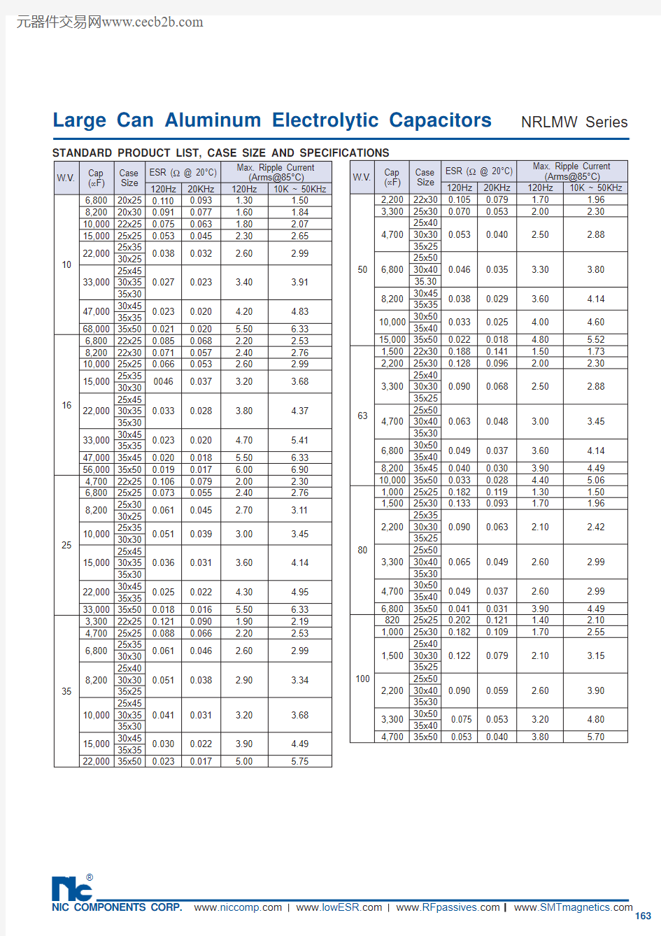
Large Can Aluminum Electrolytic Capacitors
FEATURES
? LONG LIFE (105°C, 2000 HOURS)
? LOW PROFILE AND HIGH DENSITY DESIGN OPTIONS ? EXPANDED CV VALUE RANGE
? HIGH RIPPLE CURRENT
? CAN-TOP SAFETY VENT ? DESIGNED AS INPUT FILTER OF SMPS
? STANDARD 10mm (.400") SNAP-IN SPACING NRLMW Series
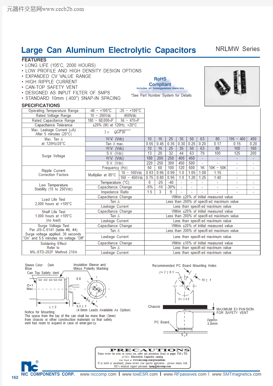
SPECIFICATIONS
Notice for Mounting
The space from the top of the can shall be more than (3mm) from chassis or other construction materials so that safety vent has room to expand in case of emer g en c y.
Sleeve Color: Dark Blue
Can Top Safety Vent
Insulation Sleeve and Minus Polarity Marking
(4.0mm Leads Available As Option)
D+1Max.
L ± 2
6.3 ± 1
0.8
10
(-)
(+)
MAXIMUM EX P AN S ION
FOR SAFETY VENT Approx. 3.0mm
Recommended PC Board Mounting Holes:
10 ± .1
?= 2 ± 0.1
D ? ± 0.5
Chassis
PC Board
PRECAUTIONS
Please review the notes on correct use, safety and precautions found on pages T10 & T11
of NIC’s Electrolytic Capacitor catalog . Operating Temperature Range
-40 ~ +105°C -25 ~ +105°C Rated Voltage Range 10 ~ 250Vdc 450Vdc Rated Capacitance Range 180 ~ 68,000μF 56 ~ 470μF Capacitance Tolerance ±20% (M) at 120Hz, +20°C
Max. Leakage Current (μA)After 5 minutes (20°C)
3 x C(μF)V
Max. Tan δat 120Hz/20°C
W.V. (Vdc)10162535506380100 ~ 400450
Tan δ max.0.550.450.350.300.250.200.170.150.20Surge Voltage
W.V. (Vdc)10162535506380100160S.V. (Vdc)132032446379100125200W.V. (Vdc)180200250400450----S.V. (Vdc)220250300450500----Ripple Current Correction Factors Frequency (Hz)
50601001205001K 10K ~ 50K --Multiplier at 85°C
16 ~ 100Vdc
0.930.950.99 1.0 1.05 1.08 1.15--160 ~ 450Vdc
0.750.800.95 1.0 1.20 1.25 1.40-Low Temperature Stability (10 to 250Vdc)Temperature (°C)0-25-40------Capacitance Change -5%-10-30%------Impedance Ratio 1.539------
Load Life Test 2,000 hours at +105°C Capacitance Change
Within ±20% of initial measured value
Tan δ
Less than 200% of speci? ed maximum value
Leakage Current Less than speci? ed maximum value Shelf Life Test 1,000 hours at +105°C
(no load)
Capacitance Change
Within ±20% of initial measured value Tan δ
Less than 200% of speci? ed maximum value
Leakage Current Less than speci? ed maximum value Surge Voltage Test
Per JIS-C-5141 (table #6, #4)Surge voltage applied: 30 seconds "On" and 5.5 minutes no voltage "Off"
Capacitance Change
Within ±20% of initial measured value Tan δ
Less than 200% of speci? ed maximum value
Leakage Current Less than speci? ed maximum value Soldering Effect
Refer to
MIL-STD-202F Method 210A
Capacitance Change
Within ±10% of initial measured value
Tan δ
Less than speci? ed maximum value Leakage Current
Less than speci? ed maximum value
RoHS
Compliant
includes all homogeneous materials *See Part Number System for Details
Large Can Aluminum Electrolytic Capacitors NRLMW Series
Large Can Aluminum Electrolytic Capacitors
NRLMW Series
NRLMW 471 M 250V 30X35 F
RoHS compliant Case Size (mm) Voltage Rating Tolerance Code Capacitance Code Series
PART NUMBER SYSTEM