LM系列可编程控制器选型手册
西门子选型手册

西门子选型手册1 6ES7 212-1AB23-0XB0 CPU(8I/6O)晶体管输出2 6ES7 212-1BB23-0XB0 CPU (8I/6O)继电器输出3 6ES7 212-1AB23-0XB8 CPU(8I/6O)晶体管输出 CN4 6ES7 212-1BB23-0XB8 CPU (8I/6O)继电器输出 CN5 6ES7 214-1AD23-0XB0 CPU(14I/10O)晶体管输出6 6ES7 214-1AD23-0XB8 CPU(14I/10O)晶体管输出 CN7 6ES7 214-1BD23-0XB0 CPU(14I/10O)继电器输出8 6ES7 214-1BD23-0XB8 CPU(14I/10O)继电器输出 CN9 6ES7 214-2AD23-0XB0 CPU224XP(14DI/10DO,2AI,1AO)晶体管输出10 6ES7 214-2BD23-0XB0 CPU224XP (14DI/10DO,2AI,1AO)继电器输出11 6ES7 214-2AD23-0XB8 CPU224XP (14DI/10DO,2AI,1AO)晶体管输出12 6ES7 214-2BD23-0XB8 CPU224XP (14DI/10DO,2AI,1AO)继电器输出13 6ES7 216-2AD23-0XB0 CPU ( 24I/16O ) 晶体管输出14 6ES7 216-2BD23-0XB0 CPU(24I/16O)继电器输出15 6ES7 216-2AD23-0XB8 CPU ( 24I/16O ) 晶体管输出 CN16 6ES7 216-2BD23-0XB8 CPU(24I/16O)继电器输出 CN17 6ES7 221-1BF22-0XA0 8点24VDC输入18 6ES7 221-1BF22-0XA8 8点24VDC输入 CN19 6ES7 221-1BH22-0XA0 16点24VDC输入20 6ES7 221-1BH22-0XA8 16点24VDC输入 CN21 6ES7 222-1HF22-0XA0 8点继电器输出22 6ES7 222-1HF22-0XA8 8点继电器输出 CN23 6ES7 222-1BF22-0XA0 8点24VDC输出24 6ES7 222-1BF22-0XA8 8点24VDC输出 CN25 6ES7 223-1PH22-0XA0 8入8出模块继电器输出26 6ES7 223-1PH22-0XA8 8入8出模块继电器输出 CN27 6ES7 223-1PL22-0XA0 16入16出模块继电器输出28 6ES7 223-1PL22-0XA8 16入16出模块继电器输出 CN29 6ES7 223-1HF22-0XA0 4入4出模块继电器输出30 6ES7 223-1HF22-0XA8 4入4出模块继电器输出 CN31 6ES7 223-1BF22-0XA0 4入4出24VDC32 6ES7 223-1BF22-0XA8 4入4出24VDC CN33 6ES7 223-1BH22-0XA0 8入8出24VDC34 6ES7 223-1BH22-0XA8 8入8出24VDC CN35 6ES7 223-1BL22-0XA0 16入16出24VDC36 6ES7 223-1BL22-0XA8 16入16出24VDC CN37 6ES7 231-0HC22-0XA0 4入模拟量模块38 6ES7 231-0HC22-0XA8 4入模拟量模块 CN39 6ES7 235-0KD22-0XA0 4入1出模拟量模块40 6ES7 235-0KD22-0XA8 4入1出模拟量模块 CN41 6ES7 232-0HB22-0XA0 2出模拟量模块42 6ES7 232-0HB22-0XA8 2出模拟量模块 CN43 6ES7 277-0AA22-0XA0 PROFIBUS-DP模块44 6ES7 272-0AA30-0YA0 TD 200显示设定单元45 6ES7 901-3CB30-0XA0 计算机编程电缆及软件46 6ES7 291-8GF23-0XA0 EEPROM 64K47 6ES7 291-8BA20-0XA0 电池48 6ES7 290-6AA20-0XA0 扩展转接电缆 0.8米49 6ES7 231-7PD22-0XA0 4路热电耦模块50 6ES7 231-7PD22-0XA8 4路热电耦模块 CN51 6ES7 231-7PB22-0XA0 2路热电阻模块52 6ES7 231-7PB22-0XA8 2路热电阻模块 CN53 6GK7243-1EX00-0XE0 以太网通讯卡西门子可编程SIEMENS S7-300系列序号型号描述1 6ES7 312-1AE13-0AB0 CPU312,16KRAM, MAX 256DI/O,64AI/O,MMC2 6ES7 312-5BE03-0AB0 CPU312C,32KRAM, 本机10I/6O,256DI/O,64AI/O,40PIN3 6ES7 313-5BF03-0AB0CPU313C,64KRAM,MAX 1016DI/O,253AI/O,2个40PIN<, /P>4 6ES7 313-6CF03-0AB0 CPU313C-2DP,64KRAM,MAX 8192DI/O,512AI/O,40PIN5 6ES7 314-1AG13-0AB0 CPU314,48KRAM,MAX1024DI/O,256AI/O,MMC6 6ES7 314-6BG03-0AB0 CPU314, 96KRAM,MAX1024DI/O,256AI/O,MMC9 6ES7 314-6CG03-0AB06ES7 315-2AG10-0AB06ES7 307-1BA00-0AA0CPU314C-2DP,96KRAM,MAX8192DI/O,512AI/O,2个40PINCPU315-2DP,128KRAM,MAX16384DI/O,1024AI/O,MMCS7-300电源DC24V,2A10 6ES7 307-1EA00-0AA0 S7-300电源DC24V,5A11 6ES7 307-1KA01-0AA0 S7-300电源DC24V,10A12 6ES7 321-1BL00-0AA0 数字输入模块32点入,DC24V13 6ES7 321-1BH02-0AA0 数字输入模块16点入,DC24V14 6ES7 321-1FF01-0AA0 8点120V/230V AC 输入15 6ES7 322-1BL00-0AA0 数字输出模块32点出,DC24V,0.5A16 6ES7 322-1HF01-0AA0 数字输出模块8点继电器出,AC220V,2A17 6ES7 322-1BH01-0AA0 数字输出模块16点出,DC24V,0.5A18 6ES7 322-1HH01-0AA0 数字输出模块16点继电器输出2A19 6ES7 322-1FH00-0AA0 数字输出模块16点输出0.5A20 6ES7 323-1BH01-0AA0 数字输入/输出模块,8入/8出,DC24V,0.5A21 6ES7 323-1BL00-0AA0 数字输入/输出模块,16入/16出,DC24V,0.5A22 6ES7 331-7KF02-0AB0 模拟量输入模板,8通道,0~10V,4~20MA23 6ES7 331-7KB02-0AB0 模拟量输入模板,2通道24 6ES7 332-5HD01-0AB0 模拟量输出模板,4通道,0~10V,4~20mA25 6ES7 332-5HB01-0AB0 模拟量输出模板,2通道26 6ES7 340-1AH02-0AE0 点对点通讯模板,CP340-1A,带RS232C口27 6ES7 340-1AH01-7BA0 CP340软件手册28 6ES7 340-1CH02-0AE0 点对点通讯模板,CP340-1C,带RS485口29 6ES7 350-1AH03-0AE0 单通道计数模块(FM350-1)30 6ES7 350-1AH00-7BG0 FM350-1组态软件手册31 6ES7 350-2AH00-0AE0 8通道计数模块(FM350-2)37 6ES7953-8LF20-0AA06ES7953-8LG11-0AA06ES7953-8LJ20-0AA06ES7953-8LL20-0AA06ES7953-8LM20-0AA06ES7 971-1AA00-0AA0 MMC 64KMMC 128KMMC 512KMMC 2MMMC 4M后备电池,3.4V,1Ah(CPU313,314用)38 6ES7 392-1AJ00-0AA0 前连接器,20针39 6ES7 392-1AM00-0AA0 前连接器,40针40 6ES7 390-1AE80-0AA0 导轨,480mm41 6ES7 390-1AF30-0AA0 导轨,530mm42 6ES7 390-1AJ30-0AA0 导轨,830mm43 6ES7 360-3AA01-0AA0 中央模板接口模板44 6ES7 361-3CA01-0AA0 扩展模板接口模板45 6ES7 365-0BA01-0AA0 接口模板(一对),带1M电缆46 6ES7 368-3BB01-0AA0 接口模板连接电缆,1M47 6ES7 368-3BC51-0AA0 接口模板连接电缆,2.5M48 6ES7 972-0CB20-0XA0 PC MPI电缆49 6ES7 972-0BA41-0XA0 L2网接口不带编程口50 6ES7 972-0BB41-0XA0 L2网接口带编程口51 6ES7 972-0AA01-0XA0 RC485 L2/MPI中继器52 6GK1 561-1AA01 CP5611 PCI通讯卡53 6GK1 561-3AA01 CP5613 PCI通讯卡54 6GK7 342-5DA02-0XE0 CP342-5通讯模块55 6A V6642-0DA01-1AX0 OP177B 5.7寸用户内存2048K 分辨率320×240 25656 6A V6642-0DC01-1AX0 OP177B 5.7寸用户内存2048K 分辨率320×240 蓝色57 6A V6 642-0AA01-0AX0 TP177A 触摸屏 5.7寸分辨率320×240 蓝色替代TP170A58 6A V6 642-0BA01-1AX0 TP177B 触摸屏 256色替代TP170B59 6A V6 641-0DD01-1AX0MP277 替代TP270-10 10.4寸用户内存6M 分辨率640×480 按键60 6ES7 354-1AH01-0AE0 FM354 伺服电机定位模块61 6ES7 355-0VH10-0AE0 带4个模拟输出的四通道闭环控制模块 FM355C62 6ES7 355-1VH10-0AE0 用于4个步进或脉冲控制器的闭环控制模块FM355S西门子可编程SIEMENS S7-400系列序号型号描述1 6ES7400-1TA01-0AA0 底板2 6ES7400-1JA01-0AA0 底板3 6ES7412-2XJ05-0AA0 CPU4124 6ES7414-2XK05-0AB0 CPU4145 6ES7407-0KA01-0AA0 10A电源6 6ES7952-1KK00-0AA0 1M存储器7 6ES7952-1KL00-0AA0 2M存储器8 6ES7971-0BA00 后备电池9 6ES7421-1BL01-0AA0 32点数字输入,24VDC10 6ES7421-7BH01-0AB0 16点数字输出,24VDC11 6ES7422-1BL00-0AA0 32点数字输出,24VDC12 6ES7422-1BH11-0AA0 16点数字输出,24VDC13 6ES7422-1HH00-0AA0 16点继电器输出14 6ES7431-7QH00-0AB0 16点模拟量输入15 6ES7431-1KF00-0AB0 8点模拟量输入16 6ES7431-7KF00-0AB0 8点模拟量输入17 6ES7431-7KF10-0AB0 8点模拟量输出18 6ES7432-1HF00-0AB0 8点模拟量输出19 6ES7460-0AA01-0AB0 扩展模块20 6ES7461-0AA01-0AA0 扩展模块21 6ES7461-0AA00-7AA0 终端电阻22 6ES7468-1BB50-0AA0 扩展电缆23 6ES7492-1AL00-0AA0 接线端子。
LM5117中文数据手册
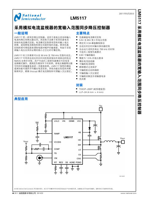
30143201 LM5117 采用模拟电流监视器的宽输入范围同步降压控制器美国国家半导体公司 301432本文是 National Semiconductor 英文版的译文,本公司不对翻译中存在的差异或由此产生的错误负责。
如需确认任何内容的准确性,请参考本公司提供的英文版。
连线图30143279顶视图20 引脚 TSSOP EP30143202顶视图LLP-24 (4 mm × 4 mm)订购信息订购号封装类型NSC 封装图纸供货方式特点LM5117PMH TSSOP-20EP MXA20A 每排 73 只LM5117PMHE TSSOP-20EP MXA20A 250 只带装和卷装LM5117PMHX TSSOP-20EP MXA20A 2500 只带装和卷装LM5117PSQ LLP-24SQA24A 1000 只带装和卷装LM5117PSQE LLP-24SQA24A 250 只带装和卷装LM5117PSQXLLP-24SQA24A4500 只带装和卷装 2L M 5117引脚描述TSSOP 引脚LLP引脚名称说明124UVLO欠压锁定编程引脚。
当 UVLO 引脚低于 0.4V 时,稳压器处于关断模式,所有功能被禁用。
如果UVLO 引脚电压高于 0.4V 并低于 1.25V,稳压器随 VCC 稳压器运行而处于待机模式,此时 SS 引脚接地,且 HO 和 LO 输出端不会切换。
如果 UVLO 引脚电压高于 1.25V,SS 引脚允许电压上升,同时脉宽调制栅极驱动信号传递至 HO 和 LO 引脚。
当 UVLO 超过 1.25V,且流经外部 UVLO 电阻时,20 µA 灌电流被激活以提供迟滞。
21DEMB可选逻辑输入可以在低态时启用二极管仿真。
在二极管仿真模式下,在检测到反向电流流过 (电流从输出到地流经低边 NMOS) 后,低边 NMOS 在 PWM 周期的其余部分被锁断。
和利时LM可编程控制器硬件手册

第1章从硬件体系结构、编程软件、快速应用等各个方面对LM小型PLC作了概述性介绍。
第2、3章主要针对CPU模块、扩展模块的技术规格、端子定义与接线示意图及等效电路进行 了详细阐述。
目录
第 1 章 概述 .......................................................................................................... 1
1.1 概述................................................................................................................................................... 1 1.2 硬件体系结构................................................................................................................................... 1
本手册仅供商业用户阅读、查询,在未得到北京和利时系统工程股份有限公司特别授权的 情况下,无论出于何种原因和目的,均不得用任何电子或机械方法,以任何形式复制和传递本 手册的内容。否则本公司将依法追究法律责任。
我们已核对本手册中的内容、图表与所述硬件设备相符,但误差难以避免,并不能保证完 全一致,还恳请广大用户批评指正。同时,我们会定期对手册的内容、图表进行检查、修改和 维护,恕不另行通知。
LabVolt系列SIEMENS ET200S IM151-8可编程逻辑控制器说明书
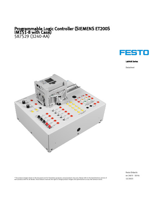
LabVolt Series DatasheetProgrammable Logic Controller (SIEMENS ET200S IM151-8 with Case)587529 (3240-AA)* The product images shown in this document are for illustration purposes; actual products may vary. Please refer to the Specifications section of each product/item for all details. Festo Didactic reserves the right to change product images and specifications at any time without notice.Festo Didactic en 240 V - 50 Hz 12/2023Programmable Logic Controller (SIEMENS ET200S IM151-8 with Case), LabVolt SeriesTable of ContentsGeneral Description_________________________________________________________________________________3 Features & Benefits_________________________________________________________________________________3 List of Manuals_____________________________________________________________________________________3 Table of Contents of the Manual(s)_____________________________________________________________________4 Additional Equipment Required to Perform the Exercises (Purchased separately) ______________________________4 Specifications______________________________________________________________________________________4 Module Options Description__________________________________________________________________________4Programmable Logic Controller (SIEMENS ET200S IM151-8 with Case), LabVolt Series•▪▪▪•••••••••••▪••General DescriptionThe Programmable Logic Controller (SIEMENS ET200S IM151-8 with Case) is specially designed to helpstudents develop skills in operating, programming, and troubleshooting modern PLC-controlled systems. Driven by a Siemens ® ET200S IM151 8 controller, the training module is compatible with several didactic applications.Listed below are the PLC applications compatible with this Programmable Logic Controller.- Traffic Lights, Model 8075-1: Full compatibility - Electro-Pneumatic, Model 8075-2: Full compatibility- Electro-Mechanical DC Motor, Model 8075-3: Full compatibility - Electro-Mechanical Step Motor, Model 8075-4: Full compatibility- Wind Turbine, Model 8075-5: Full compatibility, but requires the Analog Expansion Kit, Model 3244-C, to perform all exercises- Level Process Control, Model 8075-6: Full compatibility, but requires the Analog Expansion Kit, Model 3244-C, to perform all exercises- Bottling Process, Model 8075-7: Partial compatibility onlyFeatures & BenefitsDigital and Analog I/Os Ten 24 V dc digital inputs Six 24 V dc digital outputs Two analog inputs (0-10 V dc)24 V dc built-in power supplyBuilt-in 10/100 Mbps Ethernet/IP port for peer-to-peer messaging and programming Eight fault switches Online editingFive push-buttons, five toggle switches, and Two 0-10 V dc outputs PID CapabilityEmbedded Web server and LCD screen Onboard traffic light simulatorEasy expansion using rackless I/O modules (Analog Expansion Module, Model 3244-A)Compatibility with MicroLogix and SLC instruction setRequires the RSLogix Micro programming software, Model 3245-A ** RSLogix Micro Starter Lite for MicroLogix 1000 and 1100 is available for free on Allen-Bradleywebsite ().For programming, an Ethernet cable is included with the trainer. A serial cable, Model 3246-4, can also be orderedIncludes curriculumList of ManualsDescriptionManual numberProgrammable Logic Controller (Workbook) _____________________________________________589767 (52281-00)Programmable Logic Controller (Workbook (Instructor)) ___________________________________589768 (52281-10)Programmable Logic Controller (SIEMENS ET200S IM151-8 with Case), LabVolt Series•••••••••Table of Contents of the Manual(s)Programmable Logic Controller (Workbook) (589767 (52281-00))1 Familiarization with the PLC Trainer and RSLogix Micro2 Online Operations and Monitoring I/O Data Files3 Relay Instructions Part 14 Relay Instructions Part II5 Timer Instructions6 Counter Instructions7 Comparison Instructions8 Move Instructions9 Sequencer InstructionsAdditional Equipment Required to Perform the Exercises (Purchased separately)Qty Description Modelnumber1PLC Software (RSLogix Micro, Educational) ___________________________________________ 587552 (3245-A0)SpecificationsParameterValuePLCAllen-Bradley MicroLogix 1100Power Requirements 120-240 V, 50/60 Hz, 1.5 ASwitches (10) 5 push buttons and 5 toggle switches Inputs (10)24 V dc (four 40 kHz high-speed)Outputs (6)24 V dc (two 40 kHz high-speed), each with a pilot light Analog Inputs (2)0-10 V dc (10 bits resolution)Communication Ports (2)Ethernet, serial (DF1 full-duplex protocol)Fault-Insertion Switches 8ProtectionCircuit breakerPhysical Characteristics Dimensions (H x W x D)202 × 327 × 266 mm (8 × 12.9 × 10.5 in)Net Weight5 kg (11 lb)Module Options DescriptionPLC Software (RSLogix Micro, Educational) 587552 (3245-A0)The RSLogix Micro software is a tool to design and implement ladder programs for the Allen-Bradley MicroLogix™ family of processors (it cannot be used with SLC 500 controllers). It is a Windows ®-based application produced by Rockwell Software that allows PLC programming using a personal computer.The free-form ladder of RSLogix Micro lets students concentrate on the application logic rather than using the proper syntax when editing programs. Several other features of RSLogix Micro greatly facilitate PLC programming, such as a project verifier, drag-and-drop editing, and search-and-replace functions. The PLC can be programmed via either an RS-232 port or an Ethernetport on the PLC processor. This software comes with RSLinx™, which provides connectivity between the PLC and the computer.Programmable Logic Controller (SIEMENS ET200S IM151-8 with Case), LabVolt SeriesThe software is available with either an educational license (Model 3245-A) or as a commercial license (Model 3245-B).SpecificationsParameter ValueComputer Requirements A currently available personal computer with USB 2.0 ports, running under one of the following operating systems: Windows® 7 or Windows® 8.Programmable Logic Controller (SIEMENS ET200S IM151-8 with Case), LabVolt Series Reflecting the commitment of Festo Didactic to high quality standards in product, design, development, production, installation, and service, our manufacturing and distribution facility has received the ISO 9001 certification.Festo Didactic reserves the right to make product improvements at any time and without notice and is not responsible for typographical errors. Festo Didactic recognizes all product names used herein as trademarks or registered trademarks of their respective holders. © Festo Didactic Inc. 2023. All rights reserved.Festo Didactic SERechbergstrasse 373770 DenkendorfGermanyP. +49(0)711/3467-0F. +49(0)711/347-54-88500Festo Didactic Inc.607 Industrial Way WestEatontown, NJ 07724United StatesP. +1-732-938-2000F. +1-732-774-8573Festo Didactic Ltée/Ltd675 rue du CarboneQuébec QC G2N 2K7CanadaP. +1-418-849-1000F. +1-418-849-1666。
AVR仿PLC

LM系列PLC编程手册刘庆生2006-01-31序声明:LM系列PLC由本文作者(刘庆生)独立开发。
LM系列PLC的知识产权归本文作者所有。
如果需要技术支持请连络本文作者。
邮箱:LQSXXX888@本人曾在外资企业长期从事工厂管理、技术业务方面工作。
亲身体会到设备自动化控制的重要性。
目前在工厂中使用的PLC多数是西门子、三菱、欧姆龙、松下等公司产品,其价格十分昂贵,于是产生了LM系列PLC及其手持式编程器。
LM系列PLC在设计基本指令的符号时借鉴了三菱PLC,因此有大部份基本指令符号与三菱PLC相同。
但指令的执行过程是不相同的。
特别是指令所占用的程序步数不同。
比如:三菱PLC的PLS、PLF指令占用两步程序容量,而本PLC只占用一步程序容量。
使用者应注意到这些差异。
LM系列PLC采用固定扫描周期(10ms),PLC指令周期为2—3.5us。
目前提供两个版本,LM_M8版为简化版,除指令周期(7—9us)、提供的指令与元件不同外其它功能与LM系列保持了一致。
目前提供以下功能:1、 内置PLC语法检查器。
能够检查出几乎所有的语法错误,并返回错误代码及错误程序位置,使你能够很容易的编写出正确的PLC程序。
2、完整的外部通讯接口。
在PLC运行中,可对内部元件进行读、写操作,外部设备很容易控制PLC。
例如在操作面板上改变定时器、计数器的设定值等。
3、 L M_M8版目前支持22条指令(LD、LDI、AND、ANI、OR、ORI、ANB、ORB、OUT、PLS、PLF、SET、RST、MC、MCR、MPS、MRD、MPP、OUB、INV、NOP、END等指令)。
4、LM系列PLC在LM_M8版PLC的基础上增加了19条特殊指令(LDP、LDF、ANP、ANF、ORP、ORF、CJ、PWM、MOV、INC、DEC、ADD、SUB、FEND、CALL、SRET等指令),支持中断程序以及子程序。
并且有更多的指令正在测试之中。
Lennox M0STAT64Q-1室内机可编程控制器安装 操作说明说明书

INSTALLATION/OPERATION INSTRUCTIONSCONTROLS507644-02 6/2020Supersedes 3/2019This manual must be left with theM0STAT64Q-1 Indoor Unit Programmable Controller©2020 Lennox Industries Inc.Dallas, Texas, USAPackage 1 of 1 contains;1 – Wired Controller 1 – Lithium battery3 – Screws (mount to wall)2 – Screws (mount to J-box)2 – Plastic spacers (J-box)1 – Connection Cable A with connector for all indoor units1 – Connection Cable B with connector forMMDA/B, MCFA/B, M22A and M33A/Bindoor units 1 – Connection Cable C with connector forMWMA/B indoor units1 – Installation and operation manualInput voltage 5 VDCAmbient temperature 23~110°F (-5~43°C)Ambient humidity RH40%~RH90%The M0STAT64Q is a wired programmable local controller for mini-split indoor units with conve-nient timed schedules for daily operation. These instructions are intended as a general guide and do not supersede local codes in any way. Con-sult authorities having jurisdiction before instal-Be sure that power supply has been turned off before beginning installation. This controller should be used only as described in this man-ual. Do not install the controller on outside walls (where there is unconditioned space on opposite side of wall) or in locations where direct sunlightFigure 1. M0STAT64Q Dimensionstions for this controller. Refer to the includedwiring diagrams to connect the controller to the indoor unit.• The controller uses low voltage. Keep a mini-mum distance of 12” (305 mm) between low voltage control wire and high voltage power wires.1. Use the wiring connections illustrations (Fig-ures 2 and 6) to connect the controller to the indoor unit. NOTE - Connection details for wall-mounted units differ from the other indoorunit types.• Ground the shielded control wiring.• Do not use a megger to test insulation.• The controller cable length should not exceed 164 ft (50 m).Figure 2. Wiring Connections MMDA/B, MCFA/B, M22A and M33A/BFigure 3. MMDA/B Main BoardFigure 4. M22A and M33A/B Main BoardCN 40Connect to controllerCN 40Connect to controllerFigure 5. MCFA/B Main BoardCN 40Connect to controllerC onnect theP rogrammable Wired C ontroller to the factory installed C N4port cableFigure 6. MFMA Main BoardFigure 7. Wiring Connections MWMA/BFigure 8. MWMA/B Receiver BoardCN 403Connect to controllerCN 403 is used to connect either the M0STAT64Q local controller OR a centralized control. It is not possible to connect both the M0STAT64Q controller and a centralized control to this unit.Factory-connected toDisplay BoardWire Controller CableIndoor unit main boardCN20CN1CN4Factory installed Adapter BoardFactory installed CN4 Adapter CableOptional ProgrammableWired Controller20 Foot Cable provided with Programmable Wired ControllerFigure 9. Wiring Connections to MFMA2. Select the cable exit route from the back of the controller. Figure 10. Select Cable RoutePCBPCBPCB11123¹Use snips to notch thecontroller casing to allow the cable to pass through.3. Include a drip loop in the cable.4. Seal the cable entrance to the controller cas-ing and any wall penetrations to prevent water Figure 11. Prevent Water from EnteringController Casing5. Reattach the controller to the back plate. Be careful not to pinch or bind the wires.Figure 12. Reattach Controller to Back Plateing a flat-head screwdriver.2. Mount the back plate as appropriate for your application.Figure 13. Remove Back PlateSlotsFigure 14. Attach Back Plate to WallBack plateScrews (M4×20)Figure 15. Attach Back Plate to J-box Switch boxBack plateScrew (M4×20)Screws (M4×25)plastic spacers as needed to allow the control-ler to be mounted flush with the wall.NOTE – Be sure to provide for future mainte-nance by allowing enough slack in the wiring to allow the controller to be removed from the wall if needed.4.Insert the provided battery into controller, positive side out. The battery stores the day and time in case of power outage. Replace the battery when it’s charge is depleted. 5.Reattach the controller to the back plate. Be careful not to pinch or bind the wires.Operation ModeFanSpeedHorizontal and Vertical Swing(not available for all indoor unit models)FaceplateFunctionOn/Off TimerSchedule Follow meFunction Turbo/PTC°F or °C¹Tempera-ture displayLockIndicationRoomTemperatureClock¹ Displays cooling set point, heating set point or room temperatureNot UsedPower DecreaseFan speed (Lock)Swing but-ton (Swing function not available for all indoor unitmodels)Confirm Timer Day Off/Delete Copy/ Follow me Mode Back/Turbo Swing Timer Day o /Del Con rm Back/TurboCopy/Follow meModeFan speed (Lock)-+Increase1. Press and hold the Timer button for 3 sec-onds.2. Use the + and - buttons to select the day. The selected day will flash.3. Press the Timer button to complete the date setting.4. Use the + and - buttons to set the current time. NOTE – the controller uses a 24-hour clock.5. Press the Timer button to complete the time setting.Select Fahrenheit or Celsius for display Press and hold the Back/Turbo button and the Copy/Follow me button simultaneously for 3 sec-onds to toggle between displaying degrees Fahr-enheit or degrees Celsius.To Set Room Temperature Sensor Location Press the Copy/Follow me button to toggle be-tween having the room temperature sensed by the indoor unit or by the controller. NOTE - The Follow me indicator will display on the screen when the room temp is being sensed by the con-troller.Key Pad Tone (beep)1. Press and hold the Swing button and the Tim-er button simultaneously for 3 seconds to turn off the key pad tone.2. Press and hold the Swing button and the Tim-er button simultaneously for 3 seconds again to turn on the key pad tone.Press the Power button.To set the operation mode1. P ress the Mode button to set the operation mode.2. U se the + and - buttons to scroll through the mode selections.• Auto – System will automatically switch be-tween heating and cooling depending on the temperature sensed.• Cool – System operates in cooling mode.• Dry – System removes humidity according to preset conditions (fan speed and set point temperature, not a humidistat sensor). Can-not adjust fan speed.• Heat – System operates in heating mode.• Fan – Fan only, no heating or cooling.To Set (or change) the Set pointPress the + and - buttons to set the setpoint. NOTE - the set point range is 62-86°F (17-30°C).To Set the Fan SpeedPress the Fan speed (Lock) button to scroll through the fan speeds. Auto → Low → Med → HighTo Set Child Lock Function1. Press and hold the Fan speed (Lock) button for 3 seconds to lock all of the controller but-tons.2. Press and hold the Fan speed (Lock) button again for 3 seconds to unlock all of the but-tons.Press the Back/Turbo button to activate and de-activate the turbo functionality.• Cooling Mode - Turbo sets the indoor unit fan speed to high for a factory-set periodof time.Set Swing FunctionPress the Swing button to adjust louver direction and oscillation.3. Press the Swing button to adjust the louver position. Each press moves the louvers 6°.4. Press and hold the Swing button for two sec-onds to begin continuous louver oscillation. The Swing icon displays on the screen. Swing functionality not available for all indoor unit types.5. For cassette units only, adjust each of the four louvers independently. Press and hold the Swing button for two seconds. The Swing icon will flash. Press the increase or decrease buttons to select the louver to adjust (the -0 setting makes all louvers move at the same time). After selecting the louver to adjust, press the Swing button to adjust the louver angle. Each press moves the louver 6°.or to setup timed operation for the indoor unit. Timers are used to schedule On/Off operation only. Schedules are used to change operational settings for defined periods of time (events). Setup Timed Operation Start Time1. Press the Timer button until Day On is high-lighted.2. Press the Confirm button.3. Use the + and - buttons to set the time to start operation.4. Press the Confirm button.Setup Timed Operation Stop Time1. Press the Timer button until Day Off is high-lighted.2. Press the Confirm button.3. Use the + and - buttons to set the time to stop operation.4. Press the Confirm button.Setup Timed Operation Start and Stop Time 1. Press the Timer button until Day On/Off is highlighted.2. Press the Confirm button.3. Use the + and - buttons to set the time to start operation.4. Press the Confirm button5. Use the + and - buttons to set the time to stop operation.6. Press the Confirm button.1. Press the Timer button until Week is high-lighted.2. Press the Confirm button.3. Use the + and - buttons to select the day of the week to setup the scheduled events.4. Press the Confirm button.5. Setup the first event of the schedule.Create and Setup Scheduled Events (up to 8 events per day)1. After selecting the scheduled day.2. Use the + and - buttons to set the start time ofthe event. The display will show the event’s start time, mode, setpoint and fan speed.3. Press the Confirm button to confirm the starttime and move to the operation mode selec-tion.4. Use the + and - buttons to select the opera-tion mode for the event.5. Press the Confirm button to confirm the op-eration mode and move to the setpoint se-lection.6. Use the + and - buttons to set the setpointfor the event.7. Press the Confirm button to confirm the set-point and move to the fan speed selection.Not available when operation mode is set to Fan or Off.8. Use the + and - buttons to select the fanspeed for the event.9. Press the Confirm button to confirm the fanspeed and complete the settings for thisset to Auto, Dry or Off.10. Follow steps 2 through 9 to setup the nextevent. Each event ends at the start time of the next event.NOTE - Use the Back/Turbo button to return to the previous step during event setup.Activate and Deactivate Timed Operation1. Press the Timer button to activate timed op-eration.2. Press the Power button to deactivate timed operation.Setup Days OffSetup a day, or multiple days, within the sched-uled week for which the indoor unit will not oper-ate. When the day arrives, the unit will be pow-ered off and will not operate until the next day’s first event. Once the set day has passed, the Day Off setting is automatically removed.1. Press the Timer button.2. Press the Confirm button.3. Use the + and - buttons to select the day of the week.4. Press the Day off/Del button.5. Press the Back/Turbo button.6. Follow steps 3 and 4 for every day off required. Copy a Schedule to a New DayAll events for the scheduled day will be copied.1. Press the Timer button until Week is high-lighted.2. Press the Confirm button.3. Use the + and - buttons to select the day to copy from.4. Press the Copy/Follow Me button. The letters “CY” will be displayed on the screen.5. Use the + and - buttons to select the day to copy to.6. Press the Copy/Follow Me button to confirm.7. Press the Back/Turbo button to return to the weekly timer.8. Follow steps 3 through 7 to copy a schedule for additional days.Edit a Scheduled Event1. Press the Timer button until Week is high-lighted.2. Press the Confirm button.3. Use the + and - buttons to select the day ofthe week.4. Press the Confirm button.5. Use the + and - buttons to select the event toedit. The display will show the event’s start time, mode, setpoint and fan speed.6. Use the + and - buttons to change the starttime of the event.7. Press the Confirm button to confirm the starttime and move to the operation mode selec-tion.8. Use the + and - buttons to change the opera-tion mode for the event.9. Press the Confirm button to confirm the op-eration mode and move to the setpoint se-lection.10. Use the + and - buttons to change the set-point for the event.11. Press the Confirm button to confirm the set-point and move to the fan speed selection.Not available when operation mode is set toFan or Off.12. Use the + and - buttons to change the fanspeed for the event.13. Press the Confirm button to confirm the fanspeed and complete the changes for this event. Not available when operation mode is set to Auto, Dry or Off.NOTE - Use the Back/Turbo button to return to the previous step.Delete an Event from a Scheduled DayThis action cannot be undone.1. Press the Timer button until Week is high-lighted.2. Press the Confirm button.3. Use the + and - buttons to select the day of the week.4. Press the Confirm button.5. Use the + and - buttons to select the event to delete. The display will show the event’s start time, mode, setpoint and fan speed.6. Press the Day off/Del button.Indoor Unit Display M0STAT64QDisplayError Code DescriptionN/A F0Communication error between wired controller and indoor unit N/A F1The cassette faceplate is abnormalE0E7Indoor unit EEPROM errorE1E1Communication error between indoor unit and outdoor units E3E8Indoor fan speed errorE4E2Indoor Return air temperature sensor errorE5E3Indoor coil temperature sensor errorEC EF Low refrigerantEE EE High water level alarmF0EA Outdoor current overload sensedF1E5Outdoor ambient temperature sensor errorF2E5Outdoor coil temperature sensor errorF3E5Compressor discharge temperature sensor errorF4Ed Outdoor unit EEPROM errorF5Ed Outdoor unit fan speed errorF6E4Indoor coil outlet temperature sensor errorP0Eb Inverter module IPM errorP1N/A High or Low voltage protectionP3N/A Outdoor unit low temperature lockoutP4N/A Compressor drive errorP6N/A High pressure/ low pressure switch openP7EF Outdoor IGBT temperature sensor error。
lm3150 中文资料手册

LM3150LM3150 SIMPLE SWITCHER ® CONTROLLER, 42V Synchronous Step-DownLiterature Number: ZHCS5332008年10月17日LM3150SIMPLE SWITCHER ®42V 同步降压控制器概述特性■■■■■■■■■■■■■典型应用■■■■■典型应用30053101SIMPLE SWITCHER ® 是美国国家半导体的注册商标美国国家半导体版权所有© 2008 本文是National Semiconductor 英文版的译文,本公司不对翻译中存在的差异或由此产生的错误负责。
如需确认任何内容的准确性,请参考本公司提供的英文版。
LM3150 SIMPLE SWITCHER ®42V 同步降压控制器LM3150 SIMPLE SWITCHER ® 控制器是一款简单易用,且可在典型应用中提供达12A 输出电流的简易降压电源控制器。
工作输入电压范围为6V-42V 的LM3150的输出电压可按需要而调整,最低可达0.6V 。
开关频率可调节至达1 MHz ,且同步架构提供了更高效的设计。
具有已注册专利的仿纹波模式(ERM)控制技术的LM3150控制器采用固定导通时间(COT)结构,可使用低等效串联电阻(ESR)输出电容器,从而降低了整体设计方案尺寸和输出电压纹波。
固定导通时间(COT)调节结构具有特快的瞬态响应,且无需外置环路补偿,有助于减少外置元件数和降低设计复杂性。
故障保护特性,比如热关断、欠压锁定、过压保护、短路保护、电流限制以及输出电压预偏压启动使一种可靠且稳定的解决方案得以实现。
LM3150 SIMPLE SWITCHER ® 方案使用最少外置元件数和美国国家半导体的WEBENCH ®网上设计工具来完成整套易用设计。
WEBENCH ® 为每步设计过程提供设计支持,包括使用新的MOSFET 选择器进行外置元件计算、电气模拟、热模拟和建模板等特性。
LM25119中文数据手册

CS2 CSG2 PGND2 LO2 VCC2 SW2 HO2 HB2
电流检测放大器输入。连接至通道 2 电流检测电阻的高边。
至电流检测电阻的开尔文 (Kelvin) 接地连线。直接连接至通道 2 电流检测电阻的低边。
低边 MOSFET 栅极驱动器的电源接地返回引脚。直接连接至通道 2 电流检测电阻的低边。
VIN = 4.5V, 无外部负载 VCC = 0V VCCDIS 上升 VCCDIS = 0V 正向 VCC
UVLO 上升 UVLO = 1.4V
用于自举栅极驱动的高边驱动器电源。连接至通道 2 外部自举二极管的阴极和自举电容。自举电容 提供电流为高边 MOSFE欠压锁定编程引脚。当 UVLO 引脚低于 0.4V 时,稳压器处于关断模式,所有功能被关闭。 如果 UVLO 引脚的电压大于 0.4V 并低于 1.25V,稳压器随 VCC 稳压器运行而处于待机模式,此时 SS 引脚接地,且 HO 和 LO 输出端不会切换。如果 UVLO 引脚电压高于 1.25V,SS 引脚允许电压 上升,同时脉宽调制栅极驱动信号传递至 HO 和 LO 引脚。当 UVLO 超过 1.25V,且流经外部 UVLO 电阻时,20 µA 灌电流源被激活以提供迟滞。
即可同步至外部时钟。
14
RES
外部电容器重启定时器引脚可配置打嗝模式电流限制。在打嗝模式下自动重启前,RES 引脚上的
电容器决定控制器处于关闭状态的时间。两个稳压器通道独立运行。一个通道可能会在正常模式下
运行,而另一个处在打嗝模式过载保护状态。当通道经过了逐周期电流限制的 256 个连续 PWM
周期时,打嗝模式开始。在此之后,10 µA 灌电流源对 RES 引脚电容充电至 1.25V 阈值,重启过
低掉电控制器LM2940说明书
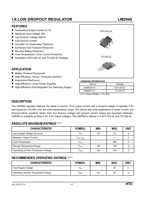
FEATURES●Guaranteed Output Current of 1A ●Maximum Input Voltage 26V●Low Dropout Voltage 400mV●Low Ground Current●Accurate 1% Guaranteed Tolerance●Extremely Fast Transient Response●Reverse Battery Protection●Over-Temperature / Over-Current Protection●Available in SOT-223-3L and TO-220-3L PackageAPPLICATION●Battery Powered Equipment●High-Efficiency “Green” Computer Systems●Automotive Electronics●High-Efficiency Linear Power Supplies●High-Efficiency Post-Regulator For Switching SupplySOT-223-3LTO-220-3LORDERING INFORMATIONDevice Package LM2940S-X.X SOT-223-3L LM2940T-X.X TO-220-3L X.X = Output Voltage = 3.3V, 5.0VDESCRIPTIONThe LM2940 regulator features the ability to source 1A of output current with a dropout voltage of typically 0.4V and maximum of 0.63V over the entire temperature range. The device also finds applications in lower current, low dropout-critical systems, where their tiny dropout voltage and ground current values are important attributes. LM2940 is available as fixed 3.3V, 5.0V output voltages. The LM2940 is offered in a SOT-223-3L and TO-220-3L.ABSOLUTE MAXIMUM RATINGS (Note 1)CHARACTERISTIC SYMBOL MIN. MAX. UNIT Input Supply Voltage (Survival) V IN-20 30 V Maximum Output Current I OUT_MAX- 1 A Lead Temperature T SOL- 260 °C Storage Temperature Range T STG-65 150 °C Operating Junction Temperature Range T OPR-40 125 °CRECOMMENDED OPERATING RATINGS (Note 2)CHARACTERISTIC SYMBOL MIN. MAX. UNIT Input Supply Voltage V IN- 26 V Operating Junction Temperature Range T OPR-40 85 °CHTCORDERING INFORMATIONV OUT Package Order No. Supplied As Status3.3VSOT-223-3L LM2940S-3.3 ReelActiveTO-220-3L LM2940T-3.3 Tube Active5.0V SOT-223-3L LM2940S-5.0 Reel ActiveTO-220-3L LM2940T-5.0 Tube ActiveHTCPIN CONFIGURATIONSOT-223-3L TO-220-3LPIN DESCRIPTIONSOT-223-3L / TO-220-3LPin No.Name Function1 VIN Input Voltage2 GND Ground3 VOUT Output VoltageHTCTYPICAL CIRCUITV IN V OUT* LM2940 can deliver a continuous current of 1A over the full operating temperature. However, the output current is limited by the restriction of power dissipation which differs from packages. A heat sink may be required depending on the maximum power dissipation and maximum ambient temperature of application.With respect to the applied package, the maximum output current of 1A may be still undeliverable.** See Application Information.*** C IN : C IN must be at least 1uF or large to maintain stability.**** C OUT : C OUT must be at least 10uF or large to maintain stability.HTCELECTRICAL CHARACTERISTICS (Note 3)Limits in standard typeface are for T J = 25°C, and limits in boldface type apply over the full operating temperature range. Unless otherwise specified: V IN (Note 4) = V O(NOM) + 1V, I OUT = 5 mA, C IN = 10 μF, C OUT = 10 μFPARAMETER SYMBOL TEST CONDITION MIN. TYP. MAX. UNIT Output Voltage Tolerance V OI OUT = 5mA -1 - 1 %5 mA ≤ I OUT≤ 1A, (V OUT+1V) ≤ V IN≤ 26V -2 - 2 % Line Regulation ΔV LINE I OUT = 5mA, (V OUT+1V) ≤ V IN≤ 26V - 0.06 0.5 % Load Regulation ΔV LOAD V IN = V OUT +1V, 5 mA ≤ I OUT≤ 1A - 0.2 1 %Output VoltageTemperature Coefficient (Note 5)ΔV OUT /ΔT - - 100 ppm/°CDropout Voltage (Note 6)V DROP I OUT = 5mA - 60 180 mV I OUT = 100mA - 170 - mV I OUT = 1A - 400 630mVGround Pin Current (Note 7)I GNDI OUT = 5mA - 250 500 μAI OUT = 1A - 16 25 mA Ground Pin Current at Dropout I GNDDO V IN = 0.5V less than specified V OUT, I OUT = 5mA - 1 - mA Current Limit I CL V OUT = 0V - 1.5 - ANote 1. Exceeding the absolute maximum ratings may damage the device.Note 2. The device is not guaranteed to function outside its operating ratings.Note 3. Stresses listed as the absolute maximum ratings may cause permanent damage to the device. These are for stress ratings. Functional operating of the device at these or any other conditions beyond those indicated in the operational sections of the specifications is not implied. Exposure to absolute maximum rating conditions for extended periods may remain possibly to affect device reliability.Note 4. The minimum operating value for input voltage is equal to either (V OUT,NOM + V DROP), whichever is greater.Note 5. Output voltage temperature coefficient is defined as the worst case voltage change divided by the total temperature range.Note 6. Dropout voltage is defined as the minimum input to output differential voltage at which the output drops 1% below the nominal value. Note 7. Ground current, or quiescent current, is the difference between input and output currents. It's defined by I GND = I IN - I OUT under the given loading condition. The total current drawn from the supply is the sum of the load current plus the ground pin current.HTCAPPLICATION INFORMATIONMaximum Output Current CapabilityThe LM2940 can deliver a continuous current of 1A over the full operating junction temperature range. However, the output current is limited by the restriction of power dissipation which differs from packages. A heat sink may be required depending on the maximum power dissipation and maximum ambient temperature of application. With respect to the applied package, the maximum output current of 1A may be still undeliverable due to the restriction of the power dissipation of LM2940. Under all possible conditions, the junction temperature must be within the range specified under operating conditions. The temperatures over the device are given by:T C = T A + P D X θCA / T J = T C + P D X θJC / T J = T A + P D X θJAwhere T J is the junction temperature, T C is the case temperature, T A is the ambient temperature, P D is the total power dissipation of the device, θCA is the thermal resistance of case-to-ambient, θJC is the thermal resistance of junction-to-case, and θJA is the thermal resistance of junction to ambient. The total power dissipation of the device is given by:P D = P IN – P OUT = (V IN X I IN)–(V OUT X I OUT)= (V IN X (I OUT+I GND)) – (V OUT X I OUT) = (V IN - V OUT) X I OUT + (V IN X I GND)where I GND is the operating ground current of the device which is specified at the Electrical Characteristics. The maximum allowable temperature rise (T Rmax) depends on the maximum ambient temperature (T Amax) of the application, and the maximum allowable junction temperature (T Jmax):T Rmax = T Jmax – T AmaxThe maximum allowable value for junction-to-ambient thermal resistance, θJA, can be calculated using the formula:θJA = T Rmax / P D = (T Jmax – T Amax) / P DLM2940 is available in SOT-223-3L package. The thermal resistance depends on amount of copper area or heat sink, and on air flow. If the maximum allowable value of θJA calculated above is over 137°C/W for SOT-223 -3L package, no heat sink is needed since the package can dissipate enough heat to satisfy these requirements. If the value for allowable θJA falls near or below these limits, a heat sink or proper area of copper plane is required. In summary, the absolute maximum ratings of thermal resistances are as follow:Absolute Maximum Ratings of Thermal ResistanceCharacteristic Symbol Rating Unit Thermal Resistance Junction-To-Ambient / SOT-223-3L θJA-SOT-223-3L137 °C/W Thermal Resistance Junction-To-Ambient / TO-220-3L θJA-TO-220-3L70 °C/WNo heat sink / No air flow / No adjacent heat source / T A=25°CHTCREVISION NOTICEThe description in this datasheet is subject to change without notice to describe its electrical characteristics properly.HTC。
LM5118中文数据手册

(注1)
-0.3V至76V -0.3 15V -0.3 15V
-0.3至HB +0.3 V -4V至76V
-0.3V到+0.3 V
RAMP,SS,COMP,FB,同步,RT到GND ESD额定值 HBM(注2)
存储温度范围
结温
-0.3 7V
2千伏 -55°C至+150°C
+150°C
工作额定值
VIN(注4) VCC,VCCX
斜坡电流1 斜坡电流2 斜坡电流3 VOUT偏置电流
LO低态输出电压 LO高态输出电压
IOHL IOLL 高方(HO)栅极驱动器 VOLH VOHH
LO上升时间 LO下降时间 卢峰源电流 LO峰值灌电流
何低电平输出电压 何高态输出电压
IOHH IOLH
BUCK-BOOST特性
热 T SD
θJA θJC
集成高侧和低侧栅极驱动器 可编程软启动时间 极低的关断电流
仿真电流斜坡.模拟电流模式控制降低了脉冲宽度调制电路的噪声 ■ 使能输入高带宽误差放大器
敏感度,允许必要在高输入电压应用的非常小的占空比的可靠控制.其 ■ 1.5%反馈参考精度
他保护功能包括电流限制,热关断和使能输入.
■ 热关断
包
采用TSSOP-20EP(裸焊盘)
95
115
135
µA
65
80
95
µA
245
µA
0.095 0.14
0.23
V
0.25
V
16
ns
14
ns
2.2
A
2.7
A
0.1
0.135
0.21
V
LM5116中文手册(DOC)
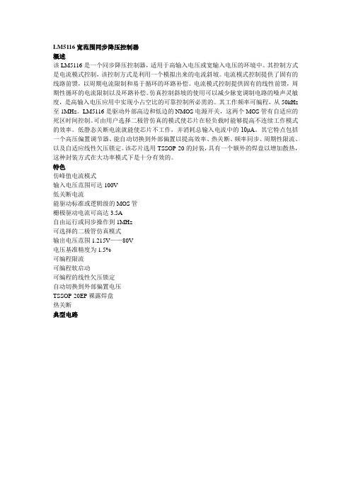
LM5116宽范围同步降压控制器概述该LM5116是一个同步降压控制器,适用于高输入电压或宽输入电压的环境中。
其控制方式是电流模式控制,该控制方式是利用一个模拟出来的电流斜坡。
电流模式控制提供了固有的线路前馈,以周期电流限制和易于循环的环路补偿。
电流模式控制提供固有的线性前馈,周期性循环的电流限制以及环路补偿。
仿真控制斜坡的使用可以减少脉宽调制电路的噪声灵敏度,是高输入电压应用中实现小占空比的可靠控制所必需的。
其工作频率可编程,从50kHz 至1MHz。
LM5116是驱动外部高边和低边的NMOS电源开关,这两个MOS管有自适应的死区时间控制。
可由用户选择二极管仿真的模式使芯片在轻负载时能够提高不连续工作模式的效率。
低静态关断电流就能使芯片不工作,并消耗总输入电流中的10μA。
其它特点包括一个高压偏置调节器、能自动切换到外部偏置以提高效率、热关断、频率同步、周期性限流、以及自适应线性欠压锁定。
该芯片选用TSSOP-20的封装,具有一个额外的焊盘以增加散热,这种封装方式在大功率模式下是十分有效的。
特色仿峰值电流模式输入电压范围可达100V低关断电流能驱动标准或逻辑级的MOS管栅极驱动电流可高达3.5A自由运行或同步操作到1MHz可选择的二极管仿真模式输出电压范围1.215V——80V电压基准精度为1.5%可编程限流可编程软启动可编程的线性欠压锁定自动切换到外部偏置电压TSSOP-20EP裸露焊盘热关断典型电路引脚名称描述1 VIN 芯片电源电压,输入电压2 UVLO 如果UVLO引脚的电压低于1.215V,调节器会进入待机模式(VCC调节器工作,开关驱动电路不工作)。
如果UVLO引脚电压高于1.215V,这个调节器正常工作。
可以通过外部分压器来设置欠压关断的阈值。
当EN引脚为高时,这个引脚存在一个固定的5μA上拉电流。
在工作在电流限制模式时,UVLO会每隔256个时钟周期被拉到地。
3 RT/SYNC 内部晶振可以通过一个该引脚和地之间的电阻来设置。
LM5116中文手册(DOC)

LM5116宽范围同步降压控制器概述该LM5116是一个同步降压控制器,适用于高输入电压或宽输入电压的环境中。
其控制方式是电流模式控制,该控制方式是利用一个模拟出来的电流斜坡。
电流模式控制提供了固有的线路前馈,以周期电流限制和易于循环的环路补偿。
电流模式控制提供固有的线性前馈,周期性循环的电流限制以及环路补偿。
仿真控制斜坡的使用可以减少脉宽调制电路的噪声灵敏度,是高输入电压应用中实现小占空比的可靠控制所必需的。
其工作频率可编程,从50kHz 至1MHz。
LM5116是驱动外部高边和低边的NMOS电源开关,这两个MOS管有自适应的死区时间控制。
可由用户选择二极管仿真的模式使芯片在轻负载时能够提高不连续工作模式的效率。
低静态关断电流就能使芯片不工作,并消耗总输入电流中的10μA。
其它特点包括一个高压偏置调节器、能自动切换到外部偏置以提高效率、热关断、频率同步、周期性限流、以及自适应线性欠压锁定。
该芯片选用TSSOP-20的封装,具有一个额外的焊盘以增加散热,这种封装方式在大功率模式下是十分有效的。
特色仿峰值电流模式输入电压范围可达100V低关断电流能驱动标准或逻辑级的MOS管栅极驱动电流可高达3.5A自由运行或同步操作到1MHz可选择的二极管仿真模式输出电压范围1.215V——80V电压基准精度为1.5%可编程限流可编程软启动可编程的线性欠压锁定自动切换到外部偏置电压TSSOP-20EP裸露焊盘热关断典型电路引脚名称描述1 VIN 芯片电源电压,输入电压2 UVLO 如果UVLO引脚的电压低于1.215V,调节器会进入待机模式(VCC调节器工作,开关驱动电路不工作)。
如果UVLO引脚电压高于1.215V,这个调节器正常工作。
可以通过外部分压器来设置欠压关断的阈值。
当EN引脚为高时,这个引脚存在一个固定的5μA上拉电流。
在工作在电流限制模式时,UVLO会每隔256个时钟周期被拉到地。
3 RT/SYNC 内部晶振可以通过一个该引脚和地之间的电阻来设置。
LM5116中文手册
LM5116宽范围同步降压控制器概述该LM5116是一个同步降压控制器,适用于高输入电压或宽输入电压的环境中。
其控制方式是电流模式控制,该控制方式是利用一个模拟出来的电流斜坡。
电流模式控制提供了固有的线路前馈,以周期电流限制和易于循环的环路补偿。
电流模式控制提供固有的线性前馈,周期性循环的电流限制以及环路补偿。
仿真控制斜坡的使用可以减少脉宽调制电路的噪声灵敏度,是高输入电压应用中实现小占空比的可靠控制所必需的。
其工作频率可编程,从50kHz 至1MHz。
LM5116是驱动外部高边和低边的NMOS电源开关,这两个MOS管有自适应的死区时间控制。
可由用户选择二极管仿真的模式使芯片在轻负载时能够提高不连续工作模式的效率。
低静态关断电流就能使芯片不工作,并消耗总输入电流中的10μA。
其它特点包括一个高压偏置调节器、能自动切换到外部偏置以提高效率、热关断、频率同步、周期性限流、以及自适应线性欠压锁定。
该芯片选用TSSOP-20的封装,具有一个额外的焊盘以增加散热,这种封装方式在大功率模式下是十分有效的。
特色仿峰值电流模式输入电压范围可达100V低关断电流能驱动标准或逻辑级的MOS管栅极驱动电流可高达3.5A自由运行或同步操作到1MHz可选择的二极管仿真模式输出电压范围1.215V——80V电压基准精度为1.5%可编程限流可编程软启动可编程的线性欠压锁定自动切换到外部偏置电压TSSOP-20EP裸露焊盘热关断典型电路引脚名称描述1 VIN 芯片电源电压,输入电压2 UVLO 如果UVLO引脚的电压低于1.215V,调节器会进入待机模式(VCC调节器工作,开关驱动电路不工作)。
如果UVLO引脚电压高于1.215V,这个调节器正常工作。
可以通过外部分压器来设置欠压关断的阈值。
当EN引脚为高时,这个引脚存在一个固定的5μA上拉电流。
在工作在电流限制模式时,UVLO会每隔256个时钟周期被拉到地。
3 RT/SYNC 内部晶振可以通过一个该引脚和地之间的电阻来设置。
海为(Haiwell)_PLC选型手册【整理精品范本】

Haiwell 厦门海为科技有限公司1、产品简介及型号说明1.1 Haiwell PLC简介Haiwell PLC是一款通用型高性价比的小型可编程控制器,产品广泛应用于塑料、包装、纺织、食品、医疗、制药、环保、市政、印刷、建材、电梯、中央空调、数控机床等领域的系统和控制设备。
Haiwell PLC除自身带有各种外设接口(开关量输入、开关量输出、模拟量输入、模拟量输出、高速计数器、高速脉冲输出通道、电源、通信端口等)外,还可扩展各种类型的扩展模块,进行灵活的配置。
海为公司拥有Haiwell PLC的全部软硬件知识产权,可以针对您的特殊要求提供定制服务,以满足各个行业不同场合的需求。
Haiwell 系列PLC已通过CE认证1。
2 Haiwell PLC的特点●硬件升级功能:无论是CPU或扩展模块,您都可以通过硬件升级功能对硬件进行免费升级,享受海为公司不断推出的各种最新功能,充分体现您的尊贵和价值。
●丰富的网络通讯功能:CPU主机内置2个通讯口,可扩展至5个通讯口,每个通讯口都可以进行编程和联网,都可作为主站或从站.支持1:N、N:1、N:N联网方式,支持各种人机界面和组态软件,可与任何带通讯功能的第三方设备(如变频器、仪表、条码阅读器等)联网。
●支持多种通讯协议:内置Modbus RTU/ASCII协议、自由通讯协议以及海为公司的HaiwellBus高速通讯协议.极为便利的通讯指令系统,使您无论使用何种通讯协议都只需一条通讯指令便可完成复杂的通讯功能,您无须再为通讯端口冲突、发送接收控制、通讯中断处理等问题烦恼,您可以在程序中混合使用各种协议轻松完成您所需的各种数据交换。
保护您原有的各项投资。
●高速并行总线:Haiwell PLC采用高速并行总线进行扩展,丰富的扩展模块类型充分满足您的各种应用需求.●高速计数功能:支持外部或内部的启动/复位控制,支持8段比较设定值,7种计数模式(脉冲/方向1倍频、脉冲/方向2倍频、正/反转脉冲1倍频、正/反转脉冲2倍频、A/B相脉冲1倍频、A/B相脉冲2倍频、A/B相脉冲4倍频), 3种比较方式(单段比较、绝对方式比较、相对方式比较),带自学习功能,并且可作为0。
lma3p型阀门控制器手持编程器说明书

LM-A3P智能阀门控制器手持编程器(通用型)说明书一、概述LM-A3P型智能阀门控制器手持编程器(下文简称“编程器”)是与LM-A3系列智能阀门控制器(下文简称“控制器”)配套的手持监控、组态设备。
编程器能够自动判别控制器的型号(开关量型LM-A3LD、模拟量型LM-A3LA),并相应实现阀位计数、状态显示、参数设置、控制方式切换等功能。
二、特点1、设置一个4位LED数码管显示器2、三个按键进行输入3、菜单式设置界面4、通过DB9接头与控制器连接5、通过数据电缆供电三、主要参数1、输入电源电压:DC3-5V、功率<1w2、工作环境温度<75ºC、湿度<90R.H.3、电缆长度<30cm四、面板说明五、基本操作将编程器电缆的DB9插头与控制器编程口连接后,打开编程器电源开关,应显示Pxxx,xxx为当前阀门开度脉冲数。
手持编程器的操作方式根据其所连接控制器的型号有所不同。
以下分别就连接开关量型(LM-A3LD)和模拟量型(LM-A3LA)予以介绍。
连接开关量型控制器时编程器的基本操作监视模式系统开机后即进入监视模式,在该模式下可以查看当前阀门开度,具有绝对值显示和百分数显示两种模式,短按●键进行切换。
1、绝对值显示模式:该模式下显示当前阀门开度的脉冲数(即圈数),当脉冲数<1000时,显示Pxxx,当脉冲数>1000时,显示xxxx。
其中xxx和xxxx为实际脉冲数。
2、百分数显示模式:该模式下显示当前开度百分数值,显示模式为dxx.x,其中00.0-99.9,100%时显示dE0.0。
设置模式长按●键2秒可进入设定模式菜单,在该模式下可以进行阀位满量程标定、就地控制阀门开关和设置输入按钮操作方式。
设定模式菜单显示为___1、___2、___3、___4、___5、___6,分别对应四种参数设定,可通过▲、▼键进行切换,短按●键进入相应设置项,长按●键退回到监视模式。
LM系列可编程控制器选型手册

03LM33104 AI,电流,电压,差分,隔离 LM3310B 4 AI,电流,电压,单端,高精度产品家族模拟量输出扩展模块 LM3320 2 AO,电流,电压网络通讯扩展模块LM3400Modbus-RTU 串口通讯扩展模块 LM3401 Porfibus-DP 从站扩展模块LM3403以太网扩展模块模拟量输入/输出扩展模块LM33304 AI,电流,电压+1 AO,电流,电压LM33138 AI,电流、电压 LM3312 4 AI,热电阻LM3317 三相交流电量采集LM33114 AI,热电偶CPU模块CPU模块结构说明0506CPU 模块CPU 模块⏹LM3104、LM3105集成8输入/6输出,共14个数字量I/O 点⏹可连接2个扩展模块,最大扩展至46路数字量I/O 点或16路模拟量I/O 点⏹120K 字节程序存储空间⏹3个独立的100kHz 高速计数器,1路独立的20kHz 高速脉冲输出(晶体管类型)⏹隔离方式:光电隔离⏹ 1个RS232通讯/编程口,专有协议、Modbus-RTU 通讯协议和自由方式通讯LM3104 14I/O晶体管输出CPU模块※ 端子定义与接线说明07CPU模块模块CPULM3105 14I/O继电器输出0809CPU模块※ 端子定义与接线说明LM3105端子定义及接线图11CPU模块※ 端子定义与接线说明LM3106端子定义及接线图12CPU模块CPU模块LM3107 24I/O 继电器输出13CPU模块※ 端子定义与接线说明LM3107 端子定义及接线图CPU模块CPU模块⏹ LM3108、LM3109集成24输入/16输出,共40个数字量I/O点Array⏹ 可连接7个扩展模块,最大扩展至152路数字量I/O点或56路模拟量I/O点⏹ 120K字节程序存储空间⏹ 3个独立的100kHz高速计数器,2路独立的20kHz高速脉冲输出(晶体管类型)⏹ 隔离方式:光电隔离⏹ 1个RS232通讯/编程口,1个RS485通讯口,专有协议、Modbus-RTU通讯协议和自由方式通讯晶体管输出LM3108 40I/O1415CPU模块※ 端子定义与接线说明LM3108 端子定义及接线图CPU模块CPU模块LM3109 40I/O继电器输出1617CPU模块※ 端子定义与接线说明LM3109 端子定义及接线图18CPU 模块CPU 模块⏹运动控制专用CPU 模块⏹额定工作电压:D C24V ⏹自带24点I/O ⏹提供14通道D C24V 输入/10通道晶体管输出处理⏹ 高速计数器:单相计数器:3点100KHz⏹ 高速输出:2点可作PWM (100KHz) 或PTO(50KHz)LM3106A 24I/O晶体管输出两相计数器:2点100KHz19CPU模块※ 端子定义与接线说明LM3106A 端子定义及接线图20CPU 模块CPU 模块LM3107E 23I/O继电器输出21CPU模块※ 端子定义与接线说明LM3107E 端子定义及接线图。
Mitsubishi Electric 电子自动化 L 系列可编程控制器 1 选择指南说明书
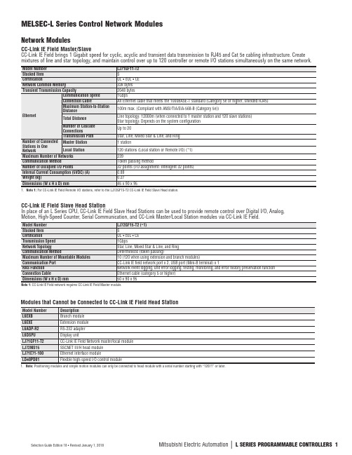
Transmission Path
RAS Function
Connection Cable
I/O Device Points Occupied
5VDC Internal Current Consumption
Weight (kg)
Dimensions (W x H x D) mm
LJ61BT11 S UL • cUL • CE 156kbps/625kbps/2.5Mbps/5Mbps/10Mbps
Model Number Stocked Item Certification Transmission Speed Network Topology Communication Method Maximum Number of Mountable Modules Communication Port RAS Function Connection Cable Dimensions (W x H x D) mm
Description
L6EXB
Branch module
L6EXE
Extension module
L6ADP-R2
RS-232 adapter
L6DSPU
Display unit
LJ71GF11-T2
CC-Link IE Field Network master/local module
LJ72MS15
CC-Link Master/Local Station Additional CC-Link Master/Local Stations can be added on and configured in GX Works2.
Model Number
Stocked Item
- 1、下载文档前请自行甄别文档内容的完整性,平台不提供额外的编辑、内容补充、找答案等附加服务。
- 2、"仅部分预览"的文档,不可在线预览部分如存在完整性等问题,可反馈申请退款(可完整预览的文档不适用该条件!)。
- 3、如文档侵犯您的权益,请联系客服反馈,我们会尽快为您处理(人工客服工作时间:9:00-18:30)。
03
LM3310
4 AI,电流,电压,差分,隔离 LM3310B 4 AI,电流,电压,单端,高精度产品家族模拟量输出扩展模块 LM3320 2 AO,电流,电压
网络通讯扩展模块
LM3400
Modbus-RTU 串口通讯扩展模块 LM3401 Porfibus-DP 从站扩展模块LM3403以太网扩展模块模拟量输入/输出扩展模块
LM3330
4 AI,电流,电压+1 AO,电流,电压
LM3313
8 AI,电流、电压 LM3312 4 AI,热电阻
LM3317 三相交流电量采集
LM33114 AI,热电偶
CPU模块CPU
模块结构说明
05
06
CPU 模块
CPU 模块
⏹
LM3104、LM3105集成8输入/6输出,共14个数字量I/O 点⏹
可连接2个扩展模块,最大扩展至46路数字量I/O 点或16路模拟量I/O 点⏹
120K 字节程序存储空间⏹
3个独立的100kHz 高速计数器,1路独立的20kHz 高速脉冲输出(晶体管类型)⏹
隔离方式:光电隔离⏹ 1个RS232通讯/编程口,专有协议、Modbus-RTU 通讯协议和自由方式通讯LM3104 14I/O
晶体管输出
CPU
模块
※ 端子定义与接线说明
07
CPU模块
模块
CPU
LM3105 14I/O继电器输出
08
09
CPU
模块
※ 端子定义与接线说明
LM3105端子定义及接线图
11
CPU
模块
※ 端子定义与接线说明
LM3106端子定义及接线图
12
CPU
模块
CPU
模块
LM3107 24I/O 继电器输出
13
CPU
模块
※ 端子定义与接线说明
LM3107 端子定义及接线图
CPU模块
CPU模块
⏹ LM3108、LM3109集成24输入/16输出,共40个数字量I/O点Array
⏹ 可连接7个扩展模块,最大扩展至152路数字量I/O点或56路模拟量I/O点
⏹ 120K字节程序存储空间
⏹ 3个独立的100kHz高速计数器,2路独立的20kHz高速脉冲输出(晶体管类型)
⏹ 隔离方式:光电隔离
⏹ 1个RS232通讯/编程口,1个RS485通讯口,专有协议、Modbus-RTU通讯协议和自由
方式通讯
晶体管输出
LM3108 40I/O
14
15
CPU
模块
※ 端子定义与接线说明
LM3108 端子定义及接线图
CPU模块
CPU模块
LM3109 40I/O
继电器输出
16
17
CPU
模块
※ 端子定义与接线说明
LM3109 端子定义及接线图
18CPU 模块
CPU 模块
⏹
运动控制专用CPU 模块⏹
额定工作电压:D C24V ⏹
自带24点I/O ⏹
提供14通道D C24V 输入/10通道晶体管输出处理⏹ 高速计数器:单相计数器:3点100KHz
⏹ 高速输出:2点可作PWM (100KHz) 或PTO(50KHz)LM3106A 24I/O
晶体管输出
两相计数器:2点100KHz
19
CPU
模块
※ 端子定义与接线说明
LM3106A 端子定义及接线图
20
CPU 模块
CPU 模块
LM3107E 23I/O
继电器输出
21
CPU
模块
※ 端子定义与接线说明LM3107E 端子定义及接线图。
