ABB变压器产品手册
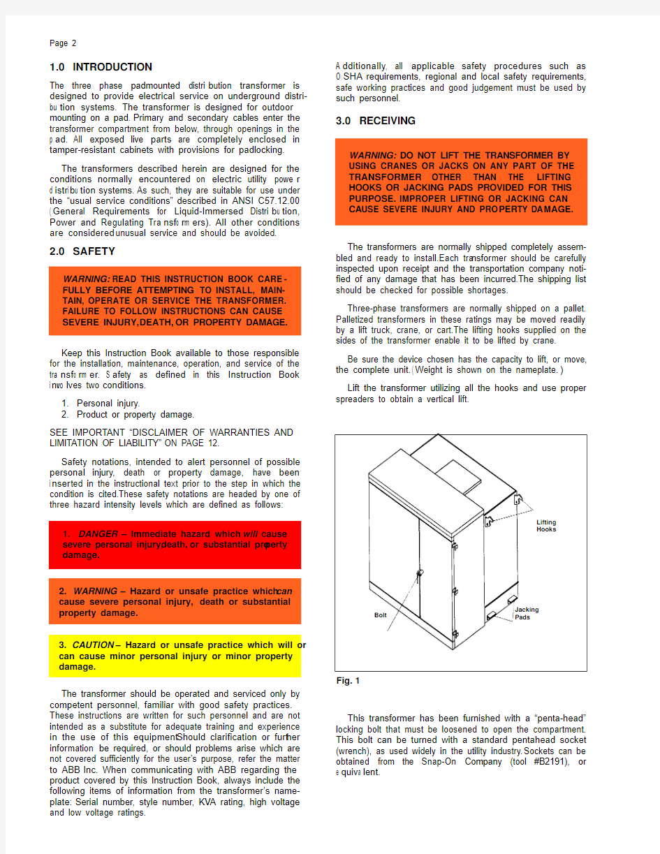
ABB Inc.
Distribution Tr ansformers
Jefferson City, MO
ISO 9001 Certified
Instruction Booklet
I.B.46-060-1,Section D
1LUJ000003-BLE
Instructions for Oil-Immersed
Distribution Transformers
Section D:Padmounted, 75-3000 KVA, Three Phase Effective:December, 2003
Supercedes I.B.46-060-1, Section D, dated
August, 2001;
January, 1998;
June, 1985 and
May, 1991
Page 2
1.0INTRODUCTION
The three phase padmounted distri b ution tra n s f o r mer is designed to provide electrical service on underground distri-bu t i o n systems.The transformer is designed for outdoor mounting on a pad.Primary and secondary cables enter the transformer compartment from below, through openings in the p a d .All exposed live parts are completely enclosed in tamper-resistant cabinets with provisions for padlocking.The transformers described herein are designed for the conditions normally encountered on electric utility powe r d i s t r i b u t i o n systems.As such, they are suitable for use under the “usual service conditions”described in ANSI C57.12.00( G e n e r al Requirements for Liquid-Immersed Distri b u t i o n ,Power and Regulating Tra n s f o r m e r s ).All other conditions are considered unusual service and should be avoided.
Keep this Instruction Book available to those responsible for the installation, maintenance, operation, and service of the tra n s f o r m e r .S a f ety as defined in this Instruction Book i n vo l v es two conditions.
1.Personal injury.
2.Product or property damage.
SEE IMPORTANT “DISCLAIMER OF WARRANTIES AND LIMITA TION OF LIABILITY”ON PAGE 12.
Safety notations, intended to alert personnel of possible personal injury, death or property damage, have been i n s e r ted in the instructional text prior to the step in which the condition is cited.These safety notations are headed by one of three hazard intensity levels which are defined as follows:2.0SAFETY
A d d i t i o n a l l y , all applicable safety procedures such as O S H A requirements, regional and local safety requirements,safe working practices and good judgement must be used by such personnel.
3.0RECEIVING
The transformers are normally shipped completely assem-bled and ready to install.Each tra n s f o r mer should be carefully inspected upon receipt and the transportation company noti-fied of any damage that has been incurred.The shipping list should be checked for possible shortages.
Three-phase transformers are normally shipped on a pallet.Palletized transformers in these ratings may be moved readily by a lift truck, crane, or cart.The lifting hooks supplied on the sides of the transformer enable it to be lifted by crane.Be sure the device chosen has the capacity to lift, or move,the complete unit.( W eight is shown on the nameplate. )Lift the transformer utilizing all the hooks and use proper spreaders to obtain a vertical lift.
This transformer has been furnished with a “penta-head”locking bolt that must be loosened to open the compartment.This bolt can be turned with a standard pentahead socket (wrench), as used widely in the utility industry.Sockets can be obtained from the Snap-On Company (tool #B2191), or e q u i v a l e n t .
The transformer should be operated and serviced only by competent personnel, familiar with good safety practices.These instructions are written for such personnel and are not intended as a substitute for adequate training and experience in the use of this equipment.Should clarification or furt h e r i n f o r mation be required, or should problems arise which are not covered sufficiently for the user’s purpose, refer the matter to ABB Inc.When communicating with ABB regarding the product covered by this Instruction Book, always include the following items of information from the transformer’s name-plate:Serial number, style number, KVA rating, high voltage and low voltage ratings.
Fig.1
WARNING:READ THIS INSTRUCTION BOOK CARE -FULLY BEFORE ATTEMPTING TO INSTALL,MAIN-TAIN,OPERATE OR SERVICE THE TRANSFORMER.
FAILURE TO FOLLOW INSTRUCTIONS CAN CAUSE SEVERE INJURY,DEATH,OR PROPERTY DAMAGE.WARNING:DO NOT LIFT THE TRANSFORMER BY USING CRANES OR JACKS ON ANY PART OF THE TRANSFORMER OTHER THAN THE LIFTING HOOKS OR JACKING PADS PROVIDED FOR THIS PURPOSE.IMPROPER LIFTING OR JACKING CAN C A USE SEVERE INJURY AND PRO P E R TY DA M A G E .
1.DANGER – Immediate hazard which will cause s e vere personal injury,d e a t h ,or substantial pro p e r t y damage.
Jacking Pads
Lifting Hooks
Bolt
2.WARNING – Hazard or unsafe practice which can cause severe personal injury,death or substantial property damage.
3.CAUTION – Hazard or unsafe practice which will or can cause minor personal injury or minor property damage.
Page 3
Fig.2
WARNING:THE OIL MUST BE AT THE PROPER LEVEL (25° C LEVEL) BEFORE VOLTA GE IS APPLIED TO THE T R A N S F O R M E R .FAILURE TO MAINTAIN THE PRO P E R OIL LEVEL CAN CAUSE SEVERE PERSONAL INJURY,DEATH OR SUBSTANTIAL PROPERTY DAMAGE.WARNING:ALWA YS VENT THE TRANSFORMER BY FOLLOWING THE INSTRUCTIONS IN SECTION 7.3.FAILURE TO DO SO CAN CAUSE SEVERE PERSONAL I N J U R Y, D E A TH OR SUBSTANTIAL PRO P E R T Y DA M A G E .
CAUTION:WHEN A TRANSFORMER IS OPENED,TAKE ACTION TO PREVENT ENTRANCE OF MOISTURE OR FOREIGN OBJECTS.MOISTURE,DIRT OR FOREIGN OBJECTS CAN WEAKEN THE INSULATION OF A TRANSFORMER AND GREATLY SHORTEN ITS LIFE.
4.0EXTERNAL INSPECTION
5.0INTERNAL TANK INSPECTION
The oil level should be checked by removing the oil level plug located at the 25° C level.Any unit which does not have the proper oil level should be checked for leaks and refilled through the vent plug before placing in serv i c e .Use only q u a l i t y oil per ASTM D3487 when adding oil to the trans-former.The transformer was filled or processed at the factory with non-PCB dielectric fluid in accordance with Federal Polychlorinated Bi-phenyl (PCB) Regulations 40 CFR 761, et seq.The non-PCB fluid contained less than 1ppm at time of processing or filling.The owner should take the necessary p r e c a u t i o n s so that PCB contamination is not introduced d u r i n g field filling or maintenance of the transformer (refer to Fib.2).
6.0STORAGE
The tra n s f o r mer should be stored completely assembl e d (tank sealed and cabinetry closed) as though it were ener-gized and at its permanent location.Tr ansformers should not be stacked on top of one another, and care must be exercised to prevent submersion in water.The transformer should be stored on a solid, level foundation.
In the event a tra n s f o r mer is to be held in storage for a p e r i o d in excess of one (1) year, it is recommended the space above the oil be pressurized with dry air to two (2) to three (3)p s i g .This will prevent moisture ingress due to negative p r e s s u r e .
The tra n s f o r mer will be ready for service at any time pro-v i d e d it has received the inspections outlined in Sections 4.0and Section 7.0 thru 7.7.
7.0INSTALLATION
Installation should comply with the latest edition of the National Electrical Code.7.1Mounting
The transformer covered by this instruction is shipped ready for installation and does not require internal inspection;however, if the transformer must be opened, prevent the entrance of moisture or other foreign material.
Oil Fill
(Vent) Plug
Oil Level Plug
Oil Level
Oil Drain Plug
High Voltage LowVoltage
WA R N I N G :FAILURE TO PRO P E R L Y MOUNT T H E TRANSFORMER CAN CAUSE SEVERE INJURY,D E A T H OR PROPERTY DAMAGE.
The tra n s f o r mers should be mounted on a flat level pad strong enough to support the weight of the tra n s f o r m e r .T h e unit should not be tilted in any direction greater than 1.5d e g r e e s , as a greater tilt will cause deviations in liquid leve l near fuses, pressure relief devices, or other accessories specifically located at or near the 25 degree C liquid leve l .
When supplied, hold down cleats or bra c kets should be used to bolt the tra n s f o r mer securely to the pad (refer to Fig.3).The tra n s f o r mer cabinet should sit flush on the pad allow-i n g no gaps which would compromise the tamper-resistance of the tra n s f o r m e r .7.2Location
Since these transformers contain a flammable insulating fluid (mineral oil), transformer failure can cause fire and/or explo-s i o n .This possibility should be considered when locating these transformers in close proximity to buildings or public t h o r o u g h f a r e s .R e f er to the latest edition of the National E l e c t r i c a l Code.7.3Venting
Vent the transformer by manually operating the pressure relief d e vice normally provided, or by removing the vent plug.The tra n s f o r m e r should be vented before it is energized if it has been pressurized for leak test or if the unit has been opened and resealed.
CAUTION:DEVIATIONS FROM SPECIFIED OIL LEVEL CAN INCREASE THE POSSIBILITY OF A DISRUPTIVE FAILURE.
Page 4
WARNING:THE TRANSFORMER MUST BE PROPERL Y G R OUNDED PRIOR TO ENERGIZING.FAILURE TO PROPERLY GROUND CAN CAUSE SEVERE INJURY OR DEATH.
WARNING:ENERGIZATION OR OPERATION OF THE TRANSFORMER WITH THE INSULATING LIQU I D LOWER THAN 1?2INCH BELOW THE 25° C LEVEL (1?2INCH BELOW THE BOTTOM EDGE OF THE LIQUID LEVEL PLUG) CAN CAUSE SEVERE INJURY,DEATH,OR PROPERTY DAMAGE.
7.4Grounding
A good, permanent low impedance ground connection must be made to the tank by using the ground pad(s) prov i d e d near the bottom of the tank for this purp o s e .
Tra n s f o r mers which are designed for use on a gr o u n d e d w y e system, that is, one having a solidly grounded neutra l ,must have the tank and other ava i l a b le neutrals perm a n e n t l y and solidly grounded to the common neutral of the system b e f ore the tra n s f o r mer is energize d .7.5Connections
During installation, the recommended sequence of connec-tions is to first make all ground connections, then the low voltage c o n n e c t i o n s , and finally the high voltage connec-t i o n s .T h e transformer should be removed from service by r e versing the above sequence of connections. C a r e f u l l y c h e c k the t r a n s f o r mer nameplate for its rating and the con-n e c t i o n s that can be made to it.Avoid excessive strain on the bushing terminals or insulators.This could loosen the contact joints or damage the insulators.7.5.1 Secondary terminations
S e c o n d a r y terminations are high current carrying dev i c e s and all bolted or crimped points should be checked pri o r to energizing the unit to assure the joints are tight.When threaded terminators are attached to the threaded secondary s t u d ,install a backup nut on the threaded secondary stud and b a c k up tightly against the threaded terminator to ensure
N e ver operate or apply voltage to tra n s f o r mer if the liquid l e vel is below the 25 degree C liquid level plug more than 1?2inch.Check the liquid level before the transformer is energized to ensure the proper liquid level.
NOTE:Cold temperatures can cause the liquid level to d r o p , through contraction, by more than 1?2i n c h .When this h a p p e n s , the liquid should be heated to allow for expansion to the proper liquid level or additional liquid is to be added to b r ing the liquid level up to within 1?2inch of the liquid leve l p l u g .This liquid will then have to be removed when the unit has reached n o r mal operating tempera t u r e .Fo l l o w the main-t e n a n c e information in Section 10.0 when adding and remov-ing any liquid.7.7Cabinet Security
Cleats
Bottom of Cabinet Compartment
Typical Bolted Cleat Assembly
20”on 46-62 Width 24”on 66-70 Width
Sill
Fig.3
m a x imum contact and to minimize joint resistance and reduce the possibility of overheating.7.6 Liquid Level
WA R N I N G :FAILURE TO PRO P E R L Y SECURE T H E CABINET MAY ALLOW ACCESS BY UNAUTHORIZED PERSONNEL WHICH CAN CAUSE SEVERE INJURY,DEATH,OR PROPERTY DAMAGE.
Before leaving the site of an energized transformer, make sure that any protective or insulating barriers are in place, the cabinet is completely closed, and all locking provisions are properly installed.
The following procedure should be used to assure cabinet security.
A.Close the high voltage (left) door and secure it in place
with the captive bolts supplied (pentahead or hexhead).B.Close the low voltage (right) door and secure it in place by
rotating the handle in a clockwise direction until seated (handle should then be in a vertical orientation).C.Tighten the safety bolt (pentahead or hexhead) located in
the locking tube until fully seated.D.Install a padlock through the door handle and lock i n g
tube and secure.E.Check both the high and low voltage doors for proper fit
and security.
8.0OPERATION
This transformer was built and tested in accordance with the latest version of the following standards of American National Standards Institute:
ANSI C57.12.00 — General Requirements for Liquid-Immersed Distri b ution, Power and Regulating Tra n s f o r m e r s .ANSI C57.12.90 — Test Code for Liquid-Immersed Distri-bution, Power and Regulating Tra n s f o r m e r s , and Guide fo r S h o r t-Circuit Testing of Distri b ution and Power Tra n s f o r m e r s .
WARNING:OPERATION OF A FUSE MAY INDICATE A FA ULTED TRANSFORMER.DO NOT REPLACE THE FUSE UNLESS THE CAUSE OF THE FUSE OPERATION IS POSITIVELY IDENTIFIED AND CORRECTED.IF THE CAUSE OF THE FUSE OPERATION CANNOT BE POSI-TIVELY IDENTIFIED AND CORRECTED,THE TRANS-FORMER SHOULD BE REPLACED OR RE-ENERGIZED F R OM A REMOTE LOCAT I O N.FAILURE TO DO SO CAN CAU S E SEVERE INJURY,DEATH OR PROPERTY DAMAGE.
WARNING:FUSES SHOULD BE OPERATED WITHIN THEIR RATINGS AND REPLACED WITH FUSES HAV-ING EQU I V ALENT VO L TAGE AND T I M E-C U R R E N T CHARACTERISTICS.FAILURE TO DO SO CAN CAUSE SEVERE INJURY,DEATH OR PROPERTY DAMAGE.WARNING:VENT THE TRANSFORMER BEFORE DIS-TURBING THE TANK SEAL.FAILURE TO DO SO CAN C A USE SEVERE INJURY, D E A TH OR PRO P E R T Y DA M A G E.
WA R N I N G:VENT THE TRANSFORMER BEFORE O P E R A T I N G THE BAY ONET FUSEHOLDER.FAILURE TO DO SO CAN CAUSE SEVERE INJURY,DEATH OR PROPERTY DAMAGE.
DA N G E R:DE-ENERGIZE THE TRANSFORMER BEFORE INSPECTING OR REPLACING THE PROTECTIVE LINK. FAILURE TO DO SO WILL CAUSE SEVERE INJURY, DEATH OR PROPERTY DAMAGE.
Page 5
The pad-mounted tra n s f o r mer is an integral part of the d i s t r i b ution system and consideration must be given to proper protection from system disturbances.P r o t e c t i o n from ex c e s s i v e voltage transients and severe ove r c u r r e n t s should be prov i d e d.To allow proper operation of ove r c u r-rent devices that may be supplied with the tra n s f o r m e r, coordination with system over-current protection must be
a c h i e ve d.
9.0ACCESSORIES AND COMPONENTS
9.1Bushings
C A U T I O N:R E M O VE ALL DIRT AN
D FOREIGN MAT E-R I A L F R OM ALL BUSHINGS BEFOR
E PLAC I N G TRANSFORMER IN SERVICE.READ AND FOLLOW THE MANUFACTURER’S INSTRUCTIONS FOR I N S T ALLING SEPA R A B L E-I N S U L A TED HIGH VO L TAGE CONNECTO R S.DO NOT ENERGIZE THE T R A N S FORMER WITH THE SHIPPING CAPS ON T H E BU S H I N G S OR INSERTS.DO NOT OPERATE THE TRANSFORMER BEYOND THE MANUFAC T U R E R’S RATING.FAILURE TO DO SO CAN CAUSE PERSONAL INJURY OR PROPERTY DAMAGE.
9.1.1 Separable Insulated Connectors
Separable insulated connectors may be universal bushing we l l s, integral bushings or bushing wells with inserts in-s t a l l e d.T h e y may be either loadbreak or non-loadbreak.All connectors must be dry and clear of any contamination b e f ore installation.U n used terminals should be properly ter-minated to prevent possible contamination.Follow the manu-fa c t u r e r’s instructions and wa r nings on the use of these t e r m i n a t i o n s.
9.1.2 Porcelain Bushings
High voltage porcelain bushings (when provided) are ex t e r-n a l l y clamped, gasketed bushings with eyebolt-type term i-n a l s.The primary cables enter the compartment from below and attach to the bushing terminals.The eyebolt-type termi-nals will accommodate No.8 through 250 kcmil cable.
9.2Fuses 9.2.1 Protective Link
The protective link is an oil-immersed high voltage expul-sion fuse designed to isolate the tra n s f o r mer from the distri-bu t i o n system in the event of a tra n s f o r mer fault inside the tank on the load side of the link.It is not designed to provide ove r load or secondary fault current protection for the t r a n s f o r m e r.
When inspecting or replacing protective links, always vent the transformer before disturbing the tank seal as outlined in Section 7.3.Care should be taken to prevent the entrance of moisture or foreign material.
For further technical information, refer to ABB TPL 44-839 .
9.2.2 Bayonet Oil Fuse
The bayonet oil fuse is a device which permits replacement of an under-oil expulsion fuse in the field, and has loadbreak capability allowing it to energize and de-energize a trans-former.
To operate or replace the fuse, follow the instructions in Fig.4.
For further technical information, refer to ABB TPL 44-835.
9.2.3 Loadbreak Drawout Fuseholder
This device combines the high interrupting capability of a
g e n e r a l p u r p o s e, current-limiting fuse with a dry -w ell fuse-
h o l d e r.The loadbreak drawout utilizes the rod and bore pri n c i-ple to accomplish loadbreak and loadmake within the F u s e h o l d e r.
To operate or replace the fuse, fo l l o w the instru c t i o n s s h o wn in Figs.5 and 6
For further technical info r mation, refer to ABB TPL 44-837.
9.2.4 Deadbreak Drawout Fuseholder
DA N G E R:DE-ENERGIZE THE TRANSFORMER BEFORE R E M O V I N G OR INSTALLING THE DEADBREAK D R A WO U T FUSEHOLDER ASSEMBLY.FAILURE TO DO SO WILL RESULT IN SEVERE INJURY,DEATH OR PROPERTY DAMAGE.
( T ext Continued on page 9)
Page 6
To operate the bayonet Loadbreak Fuseholders, it is n e c e s s a r y to raise the Hinged We a t h e r c o ver (Flip-top).With both cabinet doors fully open (over 90 degrees), push u p w ard on the front edge of the cover assembl y .Tilt the hinged cover back w ard until the supporting arm, connected to
BAYONET LOADBREAK FUSEHOLDER
WARNING:OPERATE THE FUSEHOLDER PER THESE INSTRUCTIONS.FAILURE TO DO SO CAN RESULT IN SEVERE INJURY,DEATH OR PROPERTY DAMAGE.
WARNING:VENT THE TRANS-FORMER BEFORE OPERATING THE BAYONET FUSEHOLDER.FAILURE TO DO SO CAN CAUSE SEVERE INJURY, D E A TH OR PROPERTY DAMAGE.
OPERATING INSTRUCTIONS
x
y z
{|
}
VENT THE TRANSFORMER AS OUTLINED IN SECTION 7.3.
AT T ACH HOT-LINE TOOL TO HAN-D L E EYE, STAND TO ONE SIDE AND UNLOCK THE HANDLE.
PUSH DOWN AND ROTATE T H E HANDLE 90° CLOCKWISE IN THE HOUSING TO BREAK ANY ADHE-SION BETWEEN THE GASKET AND THE HOUSING.
JERK THE FUSEHOLDER OUT APPROXIMATELY 6”TO OPEN THE CIRCUIT .WAIT A FEW SECONDS FOR OIL TO DRAIN BACK INTO THE TA N K ,THEN COMPLETELY WITHDRAW FUSEHOLDER.
TO REPLACE FUSE:
INSTRUCTIONS FOR REPLACING FUSE ELEMENT ARE PAC K E D WITH EACH REPLACEMENT FUSE.F O L L O W THE FUSE MANUFAC-TURER'S INSTRUCTIONS.
TO REINSTALL FUSEHOLDER:ATT ACH HOT -LINE TOOL TO HAN-DLE EYE, STAND TO ONE SIDE AND PLACE THE FUSEHOLDER END JUST INSIDE THE HOUSING.RAPIDLY PUSH THE FUSEHOLDER IN UNTIL
DUST CAP SEAT S AGAINST HOUSING.
PUSH DOWN AND ROTATE T H E LOCKING HANDLE.HOOKING IT OVER THE SHOULDER OF T H E HOUSING.
Fig.4
DUST CAP
the high-low barri e r , can be securely latched in place on the inside of the cove r .
Proceed with the operating instructions for the Bayo n e t Loadbreak Fuseholder (below ).
When the bayonet operations are completed, release the latch on the Hinged We a t h e r c o ver by tilting the cove r slightly backwards.Lower the cover, making sure it is all t h e way down.(The upper high-voltage door bolt should engage THROUGH the hole in the Hinged Weathercover.)
Page 7
Fig.5
CLT TYPE LOADBREAK DRAWOUT FUSEHOLDER
Dust Cap
Hook Eye
Insulating Bayonet Contact Probe
Spring Contact
Fuse
WARNING:ASSEMBLE AND OPERATE FUSEHOLDER PER THESE INSTRUCTIONS. FAILURE TO DO SO CAN RESULT IN SEVERE INJURY,DEATH OR PROPERTY DAMAGE.
OPERATING INSTRUCTIONS
LOADBREAK:A TTACH HOT-LINE TOOL TO HOOK EYE, RAPIDL Y WITHDRAW FUSEHOLDER ASSEMBL Y COMPLETELY FROM HOUSING.
LOADMAKE:A TTACH HOT-LINE TOOL TO HOOK EYE, INSERT END OF FUSEHOLDER UNTIL CONT ACT SPRING HAS JUST ENTERED HOUSING.RAPIDLY PUSH ASSEMBL Y STRAIGHT INTO THE
HOUSING UNITIL DUST CAP SEATS AGAINST HOUSING AND GROUNDING CLIP.
TO REPLACE FUSE:DISASSEMBLE BY UNSCREWING FUSE FROM INSULATING BAYONET AND CONT ACT PROBE.REPLACE BLOWN FUSE WITH NEW FUSE OF EQUIVALENT RATING AND CHARAC-
T E R I S T I C S.REASSEMBLE BY T I G H T L Y SCREWING NEW FUSE ONTO INSULAT I N G
B A YO N E T AND CONTACT PROBE.
Fig.6
NX TYPE LOADBREAK DRAWOUT FUSEHOLDER
Dust Cap
Hook Eye
Insulating Bayonet Spring Contact
Contact Probe
Locking
Set Screws
Fuse
WARNING:ASSEMBLE AND OPERATE FUSEHOLDER PER THESE INSTRUCTIONS FAILURE TO DO SO CAN RESULT IN SEVERE INJURY,DEATH OR PROPERTY DAMAGE.
OPERATING INSTRUCTIONS
LOADBREAK:A TTACH HOT-LINE TOOL TO HOOK EYE, RAPIDL Y WITHDRAW FUSEHOLDER ASSEMBL Y COMPLETELY FROM HOUSING.
LOADMAKE:A TTACH HOT-LINE TOOL TO HOOK EYE, INSERT END OF FUSEHOLDER UNTIL CONT ACT SPRING HAS JUST ENTERED HOUSING.R A P I D L Y PUSH ASSEMBLY S T R A I G H T I N T O
H O U S I N G UNTIL DUST CAP SEATS AGAINST HOUSING AND GROUNDING CLIP.
TO REPLACE FUSE:DISASSEMBLE BY UNSCREWING FUSE FROM INSULATING BAYONET AND CONT ACT PROBE.REPLACE BLOWN FUSE WITH NEW FUSE OF EQUIVALENT RATING AND CHARAC-
TERISTICS.REASSEMBLE BY TIGHTLY SCREWING NEW FUSE ONTO INSULATING BAYO-
NET AND CONTACT PROBE.
Page 8
Fig.7
CLT TYPE DEADBREAK DRAWOUT FUSEHOLDER
DE-ENERGIZED OPERATION ONL Y
Dust Cap
Hook Eye
Insulating Bayonet
Fuse Terminals
End Terminal
Spring Contact
Fuse
DA N G E R:DE-ENERGIZE THE TRANSFORMER BEFORE REMOVING OR INSTALLING THE DEADBREAK DRAWO U T FUSEHOLDER ASSEMBLY.FAILURE TO DO SO WILL RESULT IN SEVERE INJURY,D E A TH OR PR O P E R T Y DAMAGE. WARNING:ASSEMBLE AND INSTALL FUSEHOLDER PER THESE INSTRUCTIONS.FAILURE TO DO SO CAN RESULT IN SEVERE INJURY,DEATH OR PROPERTY DAMAGE.
TO REMOVE FUSE:A TTACH HOT-LINE TOOL TO HOOK EYE AND WITHDRAW FUSEHOLDER STRAIGHT OUT FROM HOUSING.
TO REPLACE FUSE:DISASSEMBLE BY UNSCREWING THE FUSE FROM THE INSULATING BAYONET.REPLACE THE BLOWN FUSE WITH A NEW FUSE OF EQUIVALENT RATING AND CHARACTERISTICS.
REASSEMBLE BY TIGHTLY SCREWING FUSE ONTO THE INSULATING BA YONET.
TO INSTALL FUSE:A TTACH HOT-LINE TOOL TO HOOK EYE AND PLACE FUSEHOLDER INTO HOUSING.PUSH FUSEHOLDER IN FIRMLY UNTIL DUST CAP IS SEATED AGAINST HOUSING AND GROUND
CLIP .
Fig.8NX TYPE DEADBREAK DRAWOUT FUSEHOLDER DE-ENERGIZED OPERATION ONL Y
Dust Cap
Hook Eye
Insulating Bayonet
Fuse Terminals
Spring Contact
Locking Set Screws
Fuse
DA N G E R:DE-ENERGIZE THE TRANSFORMER BEFORE REMOVING OR INSTALLING THE DEADBREAK DRAWO U T FUSEHOLDER ASSEMBLY.FAILURE TO DO SO WILL RESULT IN SEVERE INJURY,D E A TH OR PR O P E R T Y DAMAGE. WARNING:ASSEMBLE AND INSTALL FUSEHOLDER PER THESE INSTRUCTIONS.FAILURE TO DO SO CAN RESULT IN SEVERE INJURY,DEATH OR PROPERTY DAMAGE.
TO REMOVE FUSE:ATT ACH HOT-LINE TOOL TO HOOK EYE AND WITHDRAW FUSEHOLDER STRAIGHT OUT FROM HOUSING.
TO REPLACE FUSE:DISASSEMBLE BY UNSCREWING THE FUSE FROM THE INSULATING BAYONET.REPLACE THE BLOWN FUSE WITH A NEW FUSE OF EQUIVALENT RATING AND CHARACTERISTICS,
REASSEMBLE BY TIGHTLY SCREWING FUSE ONTO THE INSULATING BA YONET.
TO INSTALL FUSE:ATT ACH HOT-LINE TOOL TO HOOK EYE AND PLACE FUSEHOLDER INTO HOUSING.PUSH FUSEHOLDER IN FIRMLY UNTIL DUST CAP IS SEATED AGAINST HOUSING AND GROUND
CLIP.
Page 9
Fig.9
Fig.10
O
C
EFD LOADBREAK DRAWOUT FUSEHOLDER
Fuseholder Assembly
Alignment Ridges
4 Brass Screws
Hook Eye
F U S E
DA N G E R :DO NOT ATTEMPT TO REPLACE FUSES WITHOUT FIRST W I T H D R A WING THE FUSEHOLDER ASSEMBLY F R OM THE HOUSING.FAILURE TO DO SO WILL RESULT IN SEVERE INJURY,D E A TH OR PRO P E R T Y DAMAGE.WARNING:ASSEMBLE AND OPERATE FUSEHOLDER PER THESE INSTRUCTIONS.FAILURE TO DO SO CAN RESULT IN SEVERE INJURY,DEATH OR PROPERTY DAMAGE.
OPERATING INSTRUCTIONS
LOADBREAK:ATTACH HOT -LINE TOOL TO HOOK EYE, RAPIDL Y WITHDRAW FUSEHOLDER ASSEMBL Y COMPLETELY FROM HOUSING.
LOADMAKE:
ATTACH HOT -LINE TOOL TO HOOK EYE.CAREFULLY POSITION ALIGNMENT RIDGES IN THE CORRESPONDING GROOVES OF THE HOUSING.RAPIDLY PUSH THE ASSEMBLY INTO THE HOUSING UNTIL BASE OF HOOK EYE IS FLUSH WITH HOUSING.
TO REPLACE FUSE:
ONLY REPLACE FUSE WITH FUSEHOLDER WITHDRAWN FROM HOUSING.DISASSEMBLE BY REMOVING THE 4 BRASS SCREWS AND SHROUD.REPLACE BLOWN FUSE WITH A NEW FUSE OF EQUAL RATING AND CHARACTERISTICS.REASSEMBLE WITH PARTS ORIENTED AS SHOWN.RETIGHTEN THE 4 BRASS SCREWS.
This device combines the high interrupting capabilities of a general purpose, current-limiting fuse with a dry-well fuse-h o l d e r .The deadbreak drawout is normally mechanically i n t e r l o c ke d with a loadbreak switch.Once the transformer is de-energized by operation of the loadbreak switch, the safety baffle may be slid to the side, permitting access to the f u s e h o l d e r .
To replace the fuse, fo l l o w the instructions shown in F i g s .7 and 8.
For further technical info r mation, refer to ABB TPL 44-837.9.2.5 Internal Partial Range Current-Limiting Fuse The internal partial range current-limiting fuse is used in s e r ies with a low current interrupting device, such as a protec-tive link or bayonet.The partial range fuse is designed to clear low impedance (high current) faults with the expulsion fuse c l e a r ing any high impedance faults or ove r l o a d s .W h e n p r o p e r ly applied, the partial range fuse will only operate for internal transformer faults.Upon operation of a partial range fuse, it is recommended the unit be removed from service and returned to ABB Inc.for repair.9.3High Voltage Switches
9.3.1 EFD Switch
The EFD (Externally Fused Disconnect) is an air insulated
loadbreak switch ava i l a b le for radial feel (single pole).A g e n e r a l purpose current limiting fuse or a solid blade is pro-vided in the transformer connecting pole.The switch contacts are opened by drawing out the connecting pole so that they a r e completely free of the switch housing, leaving a visibl e d i s c o n n e c t .
To operate or replace the fuse, fo l l o w the instru c t i o n s s h o wn in Fig.9 .9.3.2 LBOR Switch
The ABB LBOR is a gang-operated, two position rotary oil sw i t c h .The switch is operated by attaching a hot-line tool to the ex t e r nal hook eye handle and rotating to either the “ o p e n ”or “ c l o s e d ”position (refer to Fig.1 0).Circuit connections are s h o wn on the tra n s f o r mer nameplate.
For further technical info r mation, refer to ABB TPL 44-834.
WA R N I N G :WHEN DE-ENERGIZING THE T R A N S -F O R M E R ,DO NOT RELY ON SWITCH POSITION OR OTHER V I S U AL INDICATO R S .A L WAYS ASSUME T H A T TERMINALS ARE ENERGIZED UNLESS CHECKED AND G R O U N D E D . C O N T ACT WITH AN UNGRO U N D E D T E R M I N A L CAN CAUSE ELECTRICAL SHOCK,BU R N OR DEAT H .
9.3.3 Tap Changer (Hookstick-operable)
WARNING:USE THE S & C LOADBUSTER TOOL TO O P E R A TE THE DISCONNECT.FAILURE TO DO SO CAN CAUSE SEVERE INJURY,D E A TH OR PRO P E R T Y DA M A GE.
WA R N I N G :DE-ENERGIZE THE T R A N S F O R M E R BEFORE OPERATING THE TAP CHANGER.FAILURE TO DO SO CAN CAUSE SEVERE INJURY,DEATH OR PROPERTY DAMAGE.
Page 10
The tap changer provides a means of changing the voltage ratio of a transformer.The transformers are normally supplied with an externally operated high voltage tap changer, located near the high voltage bu s h i n g .To change taps proceed as fo l -l o w s (refer to Fig.11):A.De-energize the transformer.
B.Back out the locking screw until it is clear of the locking
hole.C.Turn the handle to the desired tap position.
D.Tighten the locking screw to minimize the possibility of
unintentional movement.Some large-size units are furnished with a power-trans-fo r mer tap changer dri v e which requires pulling of a lock i n g pin and a full turn of the handle for each change in tap p o s i t i o n .
9.3.5 Arc-Strangler Fused Switch
A r c -S t r angler fused switch is mounted in the high vo l t a g e c o m p a r t m e n t .The fused disconnect(s) will have NX current-limiting fuses.Fo l l o w the McGraw Edison (Cooper I n d u s t r ies) instru c t i o n s for operating these devices.9.3.6 S & C Fused Switch
When an S & C fused switch is used, follow the manufac-t u r e r ’s instructions for operating this equipment.When opera t e d with the S & C loadbuster tool, this disconnect functions as a loadbreak switch.9.3.7 Surge Arresters
The function of a surge arrester is to intercept and divert to ground va r ious ove r voltage transients (such as lightning surges) which occur on the distribution system.
The arresters must be disconnected whenever high poten-tial or induced potential tests are made on transformers with arresters.
Locking Screw
Fig.11
9.3.4 Dual Voltage Switch (Hookstick-operable)
WA R N I N G :DE-ENERGIZE THE T R A N S F O R M E R BEFORE OPERATING THE DUAL VOLTA GE SWITCH.FAILURE TO DO SO CAN CAUSE SEVERE INJURY,DEATH OR PROPERTY DAMAGE.
WARNING:WHEN CHANGING VOLTA GE POSITION,FUSES MAY HAVE TO BE REPLACED WITH THOSE OF THE PROPER RATINGS.THE USE OF AN IMPROPERL Y RATED FUSE CAN CAUSE SEVERE INJURY,DEATH OR PROPERTY DAMAGE.
On a dual voltage switch, Position 1 is the low or multiple connected position while Position 2 is the high or series con-nected position.To change the voltage position, proceed as follows (refer to Figure 12):A.De-energize the transformer.
B.Back out the locking screw until it is clear of the locking
hole.C.Pull out on the handle until it will rotate.D.Rotate the handle to the new position.E.Release the handle.
F.Tighten the locking screw to minimize the possibility of
unintentional movement.
LOCKING SCREW
Fig.12
2
1
CAUTION:WITH THE SECONDARY CIRCUIT OPEN, THERE MAY BE SUFFICIENT COUPLING TO T H E WINDING TO CAUSE SHOCK FROM THE SECONDARY TERMINALS.GROUND THE OPEN SECONDARY TER-MINALS BEFORE WORKING ON THE SECONDA R Y S E R V I C E.
CAUTION:AN EMERGENCY CONTROL HANDLE IS PROVIDED TO RECALIBRATE THE BREAKER TO A HIGHER TRIP TEMPERATURE.THIS HANDLE SHOULD BE USED ONL Y WHEN ABSOLUTELY NECESSARY AND FOR AS SHORT A DURATION AS POSSIBLE B E C A USE ITS USE CAN CAUSE A SIGNIFICANT REDUCTION IN TRANSFORMER LIFE.Page 11
9.4LowVoltage Oil-Immersed Circuit Breaker
The low voltage oil-immersed circuit breaker is designed to open the low voltage circuit on secondary faults or excessive overloads.The low voltage breaker is not intended to protect secondary (low voltage) circuits and connected apparatus (meters, service entrance equipment, etc.) from thermal and magnetic effects due to short circuit and ove r l o a d s.T h e b r e a k e r is pri m a r ily a protective device designed for only occasional switching operations;as such it is not intended for frequent (weekly or daily) switching duty.The handle is located in low voltage compartment and should be operated with a hot-line tool.
Prior to transformer installation, reset the breaker by open-ing and closing it as follows (refer to Fig.13):
?To open the breaker manu a l l y, rotate the handle so that the pointer moves from the closed to the open position.?To close the breake r, rotate the handle past the open p o s i t i o n(to reset the breaker), then back through the open position to the closed position.
If a fault or excessive overload exists, the breaker will trip out even though the handle is held in the closed position.
Following a breaker tripout due to a long term overload, the transformer oil may not have had time to cool sufficiently to allow the breaker latch to be set, making it impossible to reclose the breaker immediately.
The breaker can be recalibrated to the emergency position by removing the meter seal and rotating the emergency con-trol handle clock w i s e.To reset the breaker to its prev i o u s s e t t i n g,return the emergency control handle to the original position.It is recommended that a new seal be applied to the handle when it is returned to the normal position to avo i d i n a d v e r t e n t operation of the emergency control.9.5 Pressure Relief Device
The standard pressure relief device, located on the tank above the liquid level, relieves excessive internal tank pres-sure and reseals at a lower positive pressure.The pressure relief device is manually operated by grasping the end-cap (or ring if provided) and slowly pulling the cap away from the tank until pressure is relieved.
9.6 Thermometer
When supplied, a thermometer indicates the liquid temper-ature near the top of the tank.The temperature sensitive ele-ment is mounted in a leakproof well, permitting removal of the thermometer without lowering the liquid level.The device is furnished with an additional pointer, red in color, to show the highest temperature attained since last reset.
9.7 Liquid Level Gauge
When supplied, a liquid level gauge is located in the low vo l t a g e compartment to indicate the variation from the 25 degree C liquid level.
9.8 Pressure-Vacuum Gauge
When supplied, a pressure gauge is located in the low vo l t a g e compartment above the bushings in the air space.The gauge indicates whether the gas space in the tank is under positive or negative pressure.
9.9 Nameplate
A nameplate is supplied on each transformer according to ANSI standard C57.12.00-1980, Section 5.12.Refer to the nameplate for transformer ratings and for proper connections of the transformer to the system.No internal connections should be made inside the transformer other than those shown on the nameplate.
10.0 MAINTENANCE
A periodic visual inspection of the tra n s f o r mer is recom-m e n d e d.At such times, the general condition of the following should be noted:
A.High voltage bushings.
B.Low voltage bushings.
C.Arresters (if provided).
D.Enclosure integrity (hinges, locking prov i s i o n s, corro-
sion, etc.)
E.Evidence of oil leakage.
F.Ground connections.
G.Accessories.
H.Safety labels.
I.Tr ansformer tilt.
WARNING:WHEN BROKEN PARTS,LEAKING OIL OR OTHER POT E N T I A L L Y HAZARDOUS CONDITIONS ARE OBSERVED,REMOVE THE TRANSFORMER FROM S E R VICE UNTIL REPAIRS CAN BE COMPLETED. FA I L U R E TO DO SO CAN CAUSE SEVERE INJURY, DEATH OR PROPERTY DAMAGE.
Where tanks show evidence of rusting or deterioration of the finish, they may be cleaned and then retouched with paint available for that purpose.When bare metal is exposed, a p r imer should initially be applied, then retouching paint applied.
Emergency
Control
Handle
O C
Fig.13
WA R N I N G :BEFORE ATTEMPTING REPA I R S , D E -ENERGIZE AND VENT THE TRANSFORMER.FAILURE TO DO SO CAN CAUSE SEVERE INJURY,DEATH,OR PROPERTY DAMAGE.
Page 12
11.0 REPAIR
A periodic check of the load should be made to ensure that the transformer is not being subjected to excessive overload.Planned overloading should be in accordance with the ANSI Loading Guide (C57.91).
When adding oil to the transformer, the owner should take the necessary precautions so that PCB contamination is not introduced.
It is the responsibility of the owner to inspect, maintain and keep the transformer in good repair.
Report all failures during the warranty period to your ABB Sales Office.All warranty repairs must be made by ABB or an approved service facility.
To assure proper operation, use only ABB approve d replacement parts.
It is recommended that the owner limit repairs to replacing b r o k en parts unless the owner has we l l -t r ained repair p e r s o n n e l .
Some internal parts can be replaced without completely draining the tank.In such cases, only the fluid necessary to expose the part should be drained.There may also be occa-sions when complete draining of the transformer tank will be necessary.
The core and coil assembly can be repaired or replaced by ABB personnel at either the factory or at an authorized repair facility.Contact ABB Inc.for details.
W h e n e ver replacement parts or info r mation regarding ex i s t i n g transformers are required, COMPLETE NAMEPLATE data including KVA rating, STYLE NUMBER, SERIAL N U M B E R ,and a DESCRIPTION of the part should be given to ABB.
DISCLAIMER OF WARRANTIES AND LIMITATION OF LIABILITY
THERE ARE NO UNDERSTANDINGS,AGREEMENTS,REPRESENTATIONS OR WARRANTIES,EXPRESS OR IMPLIED,INCLUDING WARRANTIES OR MERCHANTABILITY OR FITNESS FOR A PA R TICULAR PURPOSE,OTHER T H A N THOSE SPECIFICALLY SET OUT BY ANY EXISTING CONTRACT BETWEEN THE PARTIES.ANY SUCH CONTRACT S T ATES THE ENTIRE OBLIGATION OF SELLER.THE CONTENTS OF THIS DOCUMENT SHALL NOT BECOME PA R T OF OR MODIFY ANY PRIOR OR EXISTING AGREEMENT,COMMITMENT OR RELATIONSHIP .
The info r m a t i o n ,r e c o m m e n d a t i o n s ,descriptions and safety notations in this document are based on ABB’s ex p e r i e n c e and judgment with respect to transformers.THIS INFORMATION SHOULD NOT BE CONSIDERED TO BE ALL INCLUSIVE OR COVERING ALL CONTINGENCIES.
NO WARRANTIES,EXPRESS OR IMPLIED,INCLUDING WARRANTIES OF FITNESS FOR A PARTICULAR PURPOSE OR MERCHANTABILITY ,OR WARRANTIES ARISING FROM COURSE OF DEALING OR USAGE OF TRADE,ARE MADE REGARDING THE INFORMAT I O N ,R E C O M M E N D AT I O N S ,DESCRIPTIONS AND SAFETY NOTATIONS CONTA I N E D H E R E I N .In no event will ABB be responsible to the user in contract,in tort (including neglige n c e ),strict liability or o t h e r w i s e for any special,indirect,incidental or consequential damage or loss whatsoever including but not limited to damage to or loss of use of equipment,plant or power system,cost of capital,loss of profits or revenues,cost of replacement power,additional expenses in the use of existing power facilities,or claims against the user by its customers resulting from the use of the information,recommendations,descriptions and safety notations contained herein.
WARNING:OIL SAMPLES SHOULD BE TAKEN FROM THE TRANSFORMER ONLY AFTER DE-ENERGIZING AND MANUA L L Y VENTING THE T R A N S F O R M E R .FA I L U R E TO DO SO CAN CAUSE SEVERE INJURY,DEATH OF PROPERTY DAMAGE.
ABB Inc.
D i s t r i b ution Tra n s f o r m e r s J e f f erson City, MO
ISO 9001 Cert i f i e d
I A 66510H 01
D e c e m b e r ,2 003