温度变送器外文翻译(中英文翻译)复习过程
TT302 温度变送器
概述
TT302温度变送器接收毫伏(mV)输出的信号,这类传感器包括热电偶或阻性传感器,例如:热电阻(RTD)。它所接受的信号必须在允许的输入范围之内。允许输入电压范围为-50到500,电阻范围为0到2000欧姆。
功能描述-硬件
每个板的功能介绍如下:
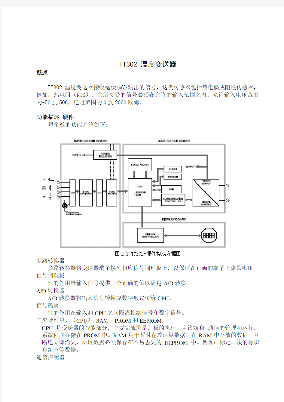
图2.1 TT302-硬件构成方框图
多路转换器
多路转换器将变送器端子接到相应信号调理板上,以保证在正确的端子上测量电压。信号调理板
他的作用给输入信号提供一个正确的值以满足A/D转换。
A/D转换器
A/D转换器将输入信号转换成数字形式传给CPU。
信号隔离
他的作用在输入和CPU之间隔离控制信号和数字信号。
中央处理单元(CPU)RAM PROM和EEPROM
CPU是变送器的智能部分,主要完成测量,板的执行,自诊断和通信的管理和运行。系统程序存储在PROM中。RAM用于暂时存放运算数据。在RAM中存放的数据一旦断电立即消失,所以数据必须保存在不易丢失的EEPROM中。例如:标定,块的标识和组态等数据。
通信控制器
监视在线动态,调整通信信号,插入,删除预处理,滤波。
电源
变送器电路通过现场总线电源供电。
电源隔离
像信号隔离一样,供给输入部分的信号必须要隔离,电源隔离采用变压器将直流供电电源转换成高频交流供电。
显示控制器
从CPU接收数据送给LCD显示器的显示部分,此时显示器必须处于打开状态。
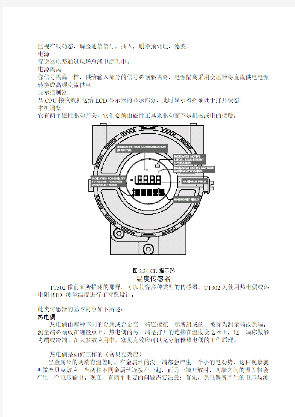
本机调整
它有两个磁性驱动开关,它们必须由磁性工具来驱动而不是机械或电的接触。
图2.2-LCD指示器
温度传感器
TT302像前面所描述的那样,可以兼容多种类型的传感器。TT302为使用热电偶或热电阻RTD 测量温度进行了特殊设计。
此类传感器的基本内容如下所述:
热电偶
热电偶由两种不同的金属或合金在一端连接在一起所组成的,被称为测量端或热端。测量端必须放在测量点上,热电偶的另一端是打开的连接在温度变送器上,这一端称做参考端或冷端。在大多数应用中,塞贝克效应可以充分解释热电偶的工作原理。
热电偶是如何工作的(塞贝克效应)
当金属丝的两端有温差时,在金属丝的没一端都会产生一个小的电动势,这种现象就叫做塞贝克效应。当两种不同金属丝连接在一起,而另一端开放时,两端之间的温差将会产生一个电压输出。现在,有两个重要的问题需要注意:首先,热电偶所产生的电压与测
量端和冷端的温度成比例,因此,为了得到被测温度必须加上参考端的温度,被称做冷端温度补偿。TT302可以自动进行补偿。为此,在TT302传感器端子装有一个温度传感器。其次,如果热电偶与变送器端子之间的导线没有采用与热电偶相同的导线(例如:由热电偶传感器或接线盒到变送器端子之间采用铜线)那么就会对温度测量产生影响,因此必须要进行冷端补偿。
热电偶的电势在冷端温度为0℃时与热端温度的关系用热电偶分度表来表示。分度表存储在TT302的存储器中,他们是国际标准NBS(B,E,J,K,N,R,S,T)和德国工业标准DIN(L,U) 热电阻(RTD)
热电阻通常被称做RTD,它的工作原理是金属的阻抗会随着温度的升高而增加,存储在TT302的中的热电阻分度表有日本工业标准JIS[1604-81] (Pt50,Pt100)。国际电工委员会IEC,DIN,JIS[1604-89] (Pt50,Pt100&Pt500),通用电气公司GE(Cu10)和DIN(Ni120)。
为使热电阻能够正确测量温度,必须消除传感器到测量电路之间线路电阻所造成的影响。在一些工业应用中,这些导线有几百米长,在环境温度变化剧烈的场所,消除线路电阻的影响是极为重要的。
TT302允许二线制连接,但可能会引起测量误差。此误差取决于接线的长度和导线经过处的温度(图2.3二线制连接)
在二线制连接中,电压U2与热电阻的阻值R TD和导线的电阻R成正比
U2=(R TD+2R X I
图2.3二线制连接
为了避免导线电阻的影响,推荐用三线制连接(图2.4三线制连接)或四线制连接(图2.5三线制连接)
在三线制连接中,端子3是高阻抗输入端,因此,没有电流流过该导线,此导线上也没有压降。电压U2-U1与电阻无关,因为导线电阻上的电压被抵消掉了,它仅与R TD的电阻有关。
U2-U1=(R TD+R)X I-RxI=R TDx I
图2.4 三线制连接
在四线制连接中,端子2和端子3是高阻抗输入端,因此,没有电流流过此端,也没有压降产生。另外两根导线的电阻可不予考虑,这两根导线上也没有测量点,因此电压U2只与R TD电阻值有关
U2=R TDx I
图2.5四线制连接
双通道连接和二线制连接相似,也存在相同的问题(图2.6双通道连接)
导线的电阻需要测量,而且在同一温度下测量也不能忽略他们的阻值,因为长度也会影响使它们不同。
图2.6双通道连接
西门子
SIMATIC PCS 7 PS 展望
投资成本低
标准化的系统基于标准化的部件,因此有高度的挠性和可变性。由于标准化技术的使用使其具有开放性
运行和维护成本低
全自动化
具有电厂设备所需的控制系统的特殊功能和部件
顾客利益
与设备的适应性强
可根据电厂的规模和特性进行扩展和改变
可改变它的性能和记忆功能
由一个服务器来实现从单一控制到分散控制
具备电厂所需的特殊运行,监视,诊断和过程接口
回顾
自1997年投入市场截止到2002年8月100﹪的销售率
在30多个国家投入使用
控制领域:
工业发电厂
生物发电厂
电厂单元机组的辅机
成功的原因
全自动化
功率方案库的使用将SIMATIC PCS 7的兼容性增强
创新性
应用国际公认标准为控制和HMI提供一种开放系统
服务范围
无论何时何地都可得到全球范围内的服务
经验
在工程和节约时间方面提供高质量的规划,管理和方案技术认证
过热器与再热器
过热器是一种将热量传给饱和蒸汽以提高其温度的换热器。蒸汽过热是中心电站所采用的设计特点之一,过热增加了整体循环效率。另外,它降低了汽轮机末级叶片的湿度,因此提高了汽机的内在效率。
一般而言,过热器可分为辐射式过热器、对流式过热器或联合式过热器,这取决于热量是怎样从烟气传给蒸汽的。这些过热器具有不同的运行特性,在机组负荷的宽范围内如能保持出口汽温不变,这样的特性是最希望的。当出口汽温变得过高,则会引起过热器因部分过热而失效。
对流过热器位于炉膛出口,或能够从燃烧的高温产物吸收热能的区域。对流过热器常常通过一束水冷管来遮蔽炉膛辐射热。当这些管子留有足够的间隔时,也能遮断渣粒而减少过热器上的结渣问题。在大型蒸汽发生器系统中,对流过热器常常分为两部分:一级过热器和二级过热器。饱和蒸汽首先进入一级过热器而接受初始过热,一级过热器为于相对低的烟温区,在部分过热后,蒸汽进到二级过热器而完成其过热过程。使过热器分为两级的主要原因是为蒸汽再热器提供一个空间,使烟气向蒸汽有效传热。
辐射过热器没有对流过热器那样得到普遍使用。当需要辐射过热器时,它通常位于炉膛壁上代替一端水冷管。另一种布置是使辐射过热器刚好在屏式管后面,辐射过热器是二级过热器的中间部分。
中心电站锅炉提供蒸汽再热。再热器一般是对流式,且通常位于一级与二级过热器之间的空间。当蒸汽温度在汽机中部分膨胀后,它返回锅炉再热。离开再热器的蒸汽温度通常等于过热蒸汽温度。因为再热器的设计在运行本质上与过热器一样,过热器的讨论将同样适用于再热器。
在过热器的热力设计中,首先确定蒸汽温度。一般而言这点在电站系统设计中完成,以平衡电站初始费用和服役期运行费用。近年来,对于所有蒸汽发生器系统,最佳蒸汽温度约538℃。热力设计中的第二步是近似确定所要求的过热器面积数量。
在过热器表面积被确定后,下一步要考虑的是选择管子的长度、管径和管子数。显然,选择是一个反复的过程,先产生一个尝试解,查看其各种约束是否满足,从各种可接受解中找到最优解。最佳过热器应该有给予设计汽温所必需的足够的传热表面。管子参数(长度和直径)使得蒸汽压降和管子金属温度将不超过设计值。管子金属温度是一个重要参数,对管子材料的选择有很大影响。另外,最佳过热器要使管子布置得使所产生的灰和渣最少。
现代过热器有许多管子通道,管子都顺排布置而不用错排布置。管子通常是圆管,外径为5或6.3cm。没有附在管子上的扩展表面(如肋片),材料的选择取决于蒸汽温度和压力。碳钢的允许温度达430℃,常常用于低温过热器。铬-钼钢、不锈钢或某种类似的耐热合金能承受高达650℃的温度,因而它们被选做高温区过热器。
温度调节与控制对过热器与再热器都很重要,蒸汽温度调节常常要在锅炉指定的时间内进行,原则方法是增加或减少传热面积。蒸汽温度也可以通过调节热烟气温度和质量流量来实现。一般而言,这些都是通过改变过量空气或者蒸发段效果来完成。
在锅炉运行中,有许多因素影响离开过热器和再热器的蒸汽温度,它们包括锅炉负荷、过量空气、给水温度和受热面的清洁度。运行中蒸汽温度的控制必须在不改变设备布置的情况下完成,最有效的措施包括:烟气旁路,燃烧器控制,温度调节,烟气再循环,过量空气以及分隔炉膛。
烟气旁路是控制烟气流过过热器的流量,这种方法是主要缺点是高温区可动闸板操作运行困难,且对负荷变化响应慢。
燃烧器控制通常是控制火焰位置和燃烧速度,使燃烧器倾斜可以使火焰指向或离开过热器,这将改变炉膛的吸热和过热器的烟气温度。随着锅炉负荷减小,燃烧器将逐一推出运行,这将改变燃烧速度,从而改变流经过热器的烟气流量。
温度调节是常使用的方法之一,温度调节器通常位于一级和二级过热器之间。有两种基本形式的温度调节器:一种是管式,一部分过热蒸汽通过换热器管道,将热量传给锅炉水(可以是锅炉给水或锅炉汽包水),随后进入温度调节,从一级过热器分开的蒸汽将会合,一起进入二级过热器;第二种温度调节器是将给水喷入过热蒸汽流中。给水蒸发使蒸汽温度降低,控制给水量就可以控制蒸汽温度。必须注意要使喷水足够纯净,喷水要和过热蒸汽很好地混合,从而使得第二级过热器的入口没有水滴。
烟气再循环通常采用改变炉膛和过热器的吸收率来控制蒸汽温度,当需要蒸汽温度声高时,从省煤器出口取出的一部分烟气将循环返回炉膛底部。因此,炉膛温度降低,导致炉膛吸热减少,而炉膛出口烟温升高。这么高的烟温,加上烟气流量增加,将增加过热器的传热速率,使蒸汽出口温度升高。
温度控制也受所使用的过量空气量的影响,过量空气越多,蒸汽出口温度将越高,其原因与烟气再循环方法的原因类似。必须指出,太多的过量空气将导致锅炉燃烧效率降低。分隔炉膛锅炉是将饱和蒸汽的生产安排在一段,而将过热蒸汽的生产安排在另一段。过热汽温是通过控制两个炉膛中的燃烧速率来调节的,这一方法不经济,很少应用中心电站锅炉。
译文:
TT302—Field bus Temperature Transmitter
Operation
The TT302 accepts signals from mV generators such as thermocouples or resistive sensors such as
RTDs. The criterion is that the signal is within the range of the input. For mV, the range is -50 to 500mV and for resistance, 0-2000 Ohm.
Functional Description – Hardware
The function of each block is described below.
Figure 2.1—TT302Block Diagram
MUX Multiplexer
The MUX multiplexes the sensor terminals to the signal conditioning section ensuring that the voltages are measured between the correct terminals.
Signal Conditioner
Its function is to apply the correct gain to the input signals to make them suit the A/D -converter. A/D Converter
The A/D converts the input signal to a digital format for the CPU.
Signal Isolation
Its function is to isolate the control and data signal between the input and the CPU.
(CPU) Central Processing Unit, RAM, PROM and EEPROM
The CPU is the intelligent portion of the transmitter, being responsible for the management and operation of measurement, block execution, self-diagnostics and communication. The program is stored in a PROM. For temporary storage of data there is a RAM. The data in the RAM is lost if the power is switched off. However there is a nonvolatile EEPROM where data that must be retained is stored. Examples, of such data are trim, calibration, block configuration and
identification data.
TT302 - Fieldbus Temperature Transmitter
Communication Controller
It monitors line activity, modulates and demodulates communication signals and inserts and deletes start and end delimiters.
Power Supply
Takes power of the loop-line to power the transmitter circuitry.
Power Isolation
Just like the signals to and from the input section, the power to the input section must be isolated. Isolation is achieved by converting the DC supply into a high frequency AC supply and galvanically separating it using a transformer.
Display Controller
Receives data from the CPU informing which segments of the Liquid Crystal Display, should be turned on.
Local Adjustment
There are two switches that are magnetically activated. They can be activated by the magnetic tool without mechanical or electrical contact.
Figure 2.2 - LCD Indicator
Temperature Sensors
The TT302, as previously explained, accepts several types of sensors. The TT302 is specially designed for temperature measurement using thermocouples or Resistive Temperature Detectors (RTDs).
Some basic concepts about these sensors are presented below.
Thermocouples
Thermocouples are constructed with two wires made from different metals or alloys joined at one end, called measuring junction or "hot junction". The measuring junction should be placed at the point of measurement. The other end of the thermocouple is open and connected to the temperature
transmitter. This point is called reference junction or cold junction.
For most applications, the Seebeck effect is sufficient to explain thermocouple behavior as following:
How the Thermocouple Works (Seebeck Effect)
When there is a temperature difference along a metal wire, a small electric potential, unique to every alloy, will occur. This phenomenon is called Seebeck effect. When two wires of dissimilar metals are joined at one end, and left open at the other, a temperature difference between the two ends will result in a voltage since the potentials generated by the dissimilar materials are different and do not cancel each other out. Now, two important things must be noted. First: the voltage generated by the thermocouple is proportional to the difference between the measuring-junction and the cold junction temperatures. Therefore the temperature at the reference junction must be added to the temperature derived from the thermocouple output, in order to find the temperature measured. This is called cold junction compensation, and is done automatically by the TT302, which has a temperature sensor at the sensor terminals for this purpose. Secondly, if the thermocouple wires are not used, all the way to the terminals of the transmitter (e.g., copper wire is used from sensor-head or marshaling box) will form new junctions with additional Seebeck effects. It will be created and ruin the measurement in most cases, since the cold-junction compensation will be done at the wrong point.
NOTE
The relation between the measuring junction temperature and the generated mili-voltage is tabulated in thermocouple calibration tables for standardized thermocouple types, the reference temperature being 0 oC.
Standardized thermocouples that are commercially used, whose tables are stored in the memory of the TT302, are the following:
. NBS (B, E, J, K, N, R, S & T)
. DIN (L & U)
Resistive Temperature Detectors (RTDs)
Resistance Temperature Detectors, most commonly known as RTD’s, are based on the principle that the resistance of metal increases as its temperature increases. Standardized RTDs, whose tables are stored in the memory of the TT302, are the following:
. JIS [1604-81] (Pt50 & Pt100)
. IEC, DIN, JIS [1604-89] (Pt50, Pt100 & Pt500)
.. GE (Cu10)
.. DIN (Ni120)
For correct measurement of RTD temperature, it is necessary to eliminate the effect of the resistance of the wires connecting the sensor to the measuring circuit. In some industrial applications, these wires may be hundreds of meters long. This is particularly important at locations where the ambient temperature changes constantly.
The TT302 permits a 2-wire connection that may cause measuring errors, depending on the length of connection wires and on the temperature to which they are exposed. (See Figure 2.3 -Two-Wire Connection).
In a 2-wire connection, the voltage V2 is proportional to the RTD resistance plus the resistance of the wires.
V2 = [RTD + 2 x R] x I
Figure 2.3 - Two-Wire Connection
In order to avoid the resistance effect of the connection wires, it is recommended to use a 3-wire connection (See Figure 2.4 – Three-Wire Connection) or a 4-wire connection (See Figure 2.5 - Four - Wire Connection).
In a 3-wire connection, terminal 3 is a high impedance input. Thus, no current flows through that wire and no voltage drop is caused. The voltage V2-V1 is independent of the wire resistances since they will be cancelled, and is directly proportional to the RTD resistance alone.
V2-V1 =[RTD + R] x I - R x I = R TD x I
Figure 2.4 - Three – Wire Connection
In a 4-wire connection, terminals 2 and 3 are high impedance inputs. Thus, no current flows through those wires and no voltage drop is caused. The resistance of the other two wires is not of interest, since there is no measurement registered on them. Hence the voltage V2 is directly proportional to the RTD resistance.
(V2 = RTD x I)
Figure 2.5 - Four - Wire Connection
A differential or dual channel connection is similar to the two-wire connection and gives the same problem (See Figure 2.6 - Differential or Dual Connection). The resistance of the wires will be measured and do not cancel each other out in a temperature measurement, since linearization will affect them differently.
Figure 2.6 - Differential or Dual Connection
SIEMENS
Highlight of SIMATIC PCS 7 PS
Low investment costs
.Modular system based on standard components, therefore high degree of flexibility and scalability.
.Open thanks to the use of standard technologies.
Low operation and maintenance costs
.Horizontal integration with Totally Integrated Au tomation.
.Control system specific functionality and components for power plant requirements. Customer Profits
.Optimum adaptation to the requirements.
.Expansion and adaptations according to size and plant characteristic. .Scalable performances and memories for control.
.Scalable from single station to distributed control system with client-server architecture.
.Power-plant-specific operation and monitoring,diagnostics and process interface.
Facts& Figures of Simatic PCS7 PS
The Scope
.On the market since 1997.
.100 sold to date (as of 08/2002).
.In use in more than 30 countries.
.In control of:
Industrial power plants
Biomass power plants
Auxiliaries of power plants
Reasons behind this success
.Totally Integrated Au tomation:
Consistent use of SIMATIC PCS7 with Power Solution Library
.Innovation Nature:
We provide an open system using international recognized standards for control and HMI
.Competence:
Worldwide services which are available for you anytime, anywhere! .Experience:
Project management and process know-how guarantee for high quality in project engineering and saving time.
Superheater and Reheater
The superheater is a heat exchanger in which heat is transferred to the saturated steam to increase its temperature. Stream superheating is one of the design features accepted in central electric power stations. Superheating raise overall cycle efficiency. In addition, it reduces a moisture level in the last stages of the steam turbine and thus increases the turbine internal efficiency.
Superheaters are commonly classified as either radiant superheaters, convective superheaters, or combined superheaters, depending on how heat id transferred from the gases to steam. These superheaters have different performance characteristics. The feature that the outlet steam temperature can stay essentially constant over a wide range of unit load is the most desirable. When the outlet steam temperature becomes excessive, it may cause failures from overheating parts of the superheater.
The convective superheater is located in the furnace exit or in the zone where it can receive thermal energy from the high temperature produces of combustion. The convective superheater is frequently screened from the furnace radiation by a bank of water-filled tubes. These tubes, when adequately spaced, can also intercept the slag particle and reduce slagging problems in superheatrs. Convective superheaters in large steam generator systems are frequently split into two parts: the primary superheater and the secondary superheaater. Saturated steam first enters the primary superheater and receives the initial heating. The primary superheater is located in a zone of relatively low gas temperature. After the partial heating steam moves to the secondary superheater and completes its superheaing process. The main reasons for splitting the superheater are to provide space for the steam reheater and to achieve an effective heat transfer from the gases the steam.
The radiant superheater is not as commonly used as the convective superheater. When the radiant superheater is needed, it is usually placed on the furnace wall replacing a section of water-filled tubes. Another arrangement is to have the radiant superheater just behind the screen tubes. The radiant superheater is an integral part of the secondary superheater.
Central station boilers provide for steam reheating. The reheater is essentially a convective type and usually located in the space between thee primary and secondary superheaters. After steam partially expands in the tubine, it returns to the boiler for reheating. The temperature of steam leaving the reheater is usually equal to the superheated steam temperature. Since the design and operation of reheater are essentially the same as superheaters, the discussion of superheaters will be equally applicable to reheaters.
In superheater thermal design, the steam temperature is first determined. This is generally accomplished in the plant system design, balancing the plant initial cost against the lifttime operating cost. In recent years the optimum steam temperature is approximately 538℃ for all large steam generation systems. In the second step, the amount of superheater surface required is approximated.
After the amount of superheater surface id determined, the next consideration is to select the tube length, tube diameter, and the number of tubes. Evidently, the selection is an iterative process, generating a trial solution and checking to see whether all constraints are met. From several acceptable solutions, the optimum is found. The optimum superheater should have enough heat transfer surface necessary to give the design steam temperature. The tube parameters(length and diameter) are such that the steam pressure drop and tube metal temperature will
not exceed the design values. The tube metal temperature is an important parameter and has a strong influence on the tube material selection. In addition, the optimum superheater should have its tubes so spaced that minimum ash and slag deposits will result.
Modern superheaters have many tube passes, and the tubes are arranged in-line rather than staggered. The tubes are usually cylindrical and have 5 or 6.3cm outside diameter. There is no extended surface(i.e.fins)attached to the tubes. The material selection depends on the steam temperature and pressure. Carbon steel has an allowable temperature up to 430℃ and is frequently used for loe-temperature superheaters. Chrome-moly, stainless steel, or same similar heat resistant alloy can withstand the temperature up to 650℃. Therefore they are selected for the Superheater in a high-temperature zone.
Temperature regulation and control are importation for both superheaters and reheaters. Steam temperature adjustments are frequently made at the time of the commissioning of a boiler. The principal methods are an addition or regulating the hot gas temperature and mass flow rate. These are generally accomplished by changing the excess air or the effectiveness of the evaporation section.
During a boiler operation, there are many factors affecting the temperature of steam leaving the superheater and reheater. These include a boiler load, excess air, feedwater temperature, and cleanliness of heating surfaces. Control of steam temperature during operation must be done without changing the arrangement of equipment. The most effective approaches are gas bypass, burner control, attemperation, gas recirculation, excess air, divided furnace.
A gas bypass is to control the gas flow rate to superheater. The main disadvantages of this approach are the operating difficulties experienced by the movable dampers located in the high-temperature zone and the slow response to load change.
Burner control is used to control the flame location and combustion rate. Tilting burners can direct the flame toward or away from the superheater. These will result in a change of heat absorption in the furnace and change of gas temperature in the superheater. As the boiler load is reduced, burners are removed one by one from service. This will change the combustion rate and, thus, change the gas flow rate to the superheater.
Attemperation is one of approaches frequently used. The attemperator is usually located at the point between the primary and secondary superheaters.
There are two basic types of attemperator. The first is the tubular type in which some of superheated steam is passed through the tubes of a heat exchanger and has heat transferred to the boiler water(either boiler feedwater or water in the boiler drum).Subsequent to attemperation, the divided streams from the primary superheater will combine and enter the secondary superheater.
The second type of attemperator involves a spray of feedwater into the atream ofsuperheated steam. The feedwater evaporates and reduces the steam temperature. Controlling the amount of feedwater will result in control of the ateam temperature. Care must be exercised to ensure that the spray water has sufficient purity. The
spray water should mix well with the superheated steam so that there are no water droplets in the inlet of the secondary superjeater.
Gas recirculation is used to control the steam temperature by changing the heat absorption rates both in the furnace and in the superheater. When the ateam temperature needs to be raised, some of the furnace. Therefore, the furnace temperature will become lower, resulting in a lower heat absorption in the furnace and thereby a higher flue gas temperature in the furnace exit. This high gas temperature, combined with an increase in the gas floe rate, will increase the heat transfer rate in the superheater and thus increase the steam outlet temperature.
Temperature control can be affected bu using different amounts of excess air. the more the excess air, the higher the steam outlet temperature would be. The reasons for this are similar to those for the gas recirculation method. It must be pointed out, however, that too much excess air will result in a reduction of boiler combustion efficiency. A divided-furnace boiler is usually arranged with a generation of saturated steam in one section and a superheating of steam in another section. The temperature of the superheated steam is regulated by controlling the firing rates in the two furnaces. This method is not economical and is seldom applied in a central electric power station.
DS18B20 单线温度传感器外文翻译
DS18B20单线温度传感器 一.特征:ucts DS18B20 data sheet 2012 ●独特的单线接口,只需1个接口引脚即可通信 ●每个设备都有一个唯一的64位串行代码存储在ROM上 ●多点能力使分布式温度检测应用得以简化 ●不需要外部部件 ●可以从数据线供电,电源电压范围为3.0V至5.5V ●测量范围从-55 ° C至+125 ° C(-67 ° F至257 ° F),从-10℃至+85 °C的精 度为0.5 °C ●温度计分辨率是用户可选择的9至12位 ●转换12位数字的最长时间是750ms ●用户可定义的非易失性的温度告警设置 ●告警搜索命令识别和寻址温度在编定的极限之外的器件(温度告警情况) ●采用8引脚SO(150mil),8引脚SOP和3引脚TO - 92封装 ●软件与DS1822兼容 ●应用范围包括恒温控制工业系统消费类产品温度计或任何热敏系统二.简介 该DS18B20的数字温度计提供9至12位的摄氏温度测量,并具有与非易失性用户可编程上限和下限报警功能。信息单线接口送入DS18B20或从DS18B20 送出,因此按照定义只需要一条数据线与中央微处理器进行通信。它的测温范围从-55°C到+125°C,其中从-10 °C至+85 °C可以精确到0.5°C 。此外,DS18B20可以从数据线直接供电(“寄生电源”),从而消除了供应需要一个外部电源。 每个DS18B20 的有一个唯一的64位序列码,它允许多个DS18B20的功
能在同一总线。因此,用一个微处理器控制大面积分布的许多DS18B20是非常简单的。此特性的应用范围包括HV AC、环境控制、建筑物、设备或机械内的温度检测以及过程监视和控制系统。 三.综述 64位ROM存储设备的独特序号。存贮器包含2个字节的温度寄存器,它存储来自温度传感器的数字输出。此外,暂存器可以访问的1个字节的上下限温度告警触发器(TH和TL)和1个字节的配置寄存器。配置寄存器允许用户设置的温度到数字转换的分辨率为9,10,11或12位。TH,TL和配置寄存器是非易失性的,因此掉电时依然可以保存数据。 该DS18B20使用Dallas的单总线协议,总线之间的通信用一个控制信号就可以实现。控制线需要一个弱上拉电阻,因为所有的设备都是通过3线或开漏端口连接(在DS18B20中用DQ引脚)到总线的。在这种总线系统中,微处理器(主设备)和地址标识上使用其独有的64位代码。因为每个设备都有一个唯一的代码,一个总线上连接设备的数量几乎是无限的。单总线协议,包括详细的解释命令和“时间槽”,此资料的单总线系统部分包括这些内容。 DS18B20的另一个特点是:没有外部电源供电仍然可以工作。当DQ引脚为高电平时,电压是单总线上拉电阻通过DQ引脚供应的。高电平信号也可以充当外部电源,当总线是低电平时供应给设备电压。这种从但总线提供动力的方法被称为“寄生电源“。作为替代电源,该DS18B20也可以使用连接到VDD 引脚的外部电源供电。 四.运用——测量温度 该DS18B20的核心功能是它是直接输出数字信号的温度传感器。该温度传
机械手机械设计论文中英文资料对照外文翻译
中英文资料对照外文翻译 机械设计 摘要: 机器由机械和其他元件组成的用来转换和传输能量的装置。比如:发动机、涡轮机、车、起重机、印刷机、洗衣机和摄影机。许多机械方面设计的原则和方法也同样适用于非机械方面。术语中的“构造设计”的含义比“机械设计”更加广泛,构造设计包括机械设计。在进行运动分析和结构设计时要把产品的维护和外形也考虑在机械设计中。在机械工程领域中,以及其它工程领域,都需要机械设备,比如:开关、凸轮、阀门、船舶以及搅拌机等。 关键词:设计流程设计规则机械设计 设计流程 设计开始之前就要想到机器的实用性,现有的机器需要在耐用性、效率、重量、速度,或者成本上得到改善。新的机器必需能够完全或部分代替以前人的功能,比如计算、装配、维修。 在设计的初级阶段,应该充分发挥设计人员的创意,不要受到任何约束。即使有一些不切实际的想法,也可以在设计的早期,即在绘制图纸之前被改正掉。只有这样,才不致于阻断创新的思路。通常,必须提出几套设计方案,然后进行比较。很有可能在这个计划最后指定使用某些不在计划方案内的一些想法的计划。 一般当产品的外型和组件的尺寸特点已经显现出来的时候,就可以进行全面的设计和分析。接着还要客观的分析机器性能、安全、重量、耐用性,并且成本也要考虑在内。每一个至关重要的部分要优化它的比例和尺寸,同时也要保持与其它组成部分的平衡。 选择原材料和工艺的方法。通过力学原理来分析和实现这些重要的特性,如稳定和反应的能量和摩擦力的利用,动力惯性、加速度、能量;包括材料的弹性强度、应力和刚度等物理特性,以及流体的润滑和驱动器的流体力学。设计的过程是一个反复与合作的过程,无论是正式的还是非正式的,对设计者来说每个阶段都很重要。。产品设计需要大量的研究和提升。许多的想法,必须通过努力去研究成为一种理念,然后去使用或放弃。
英文文献翻译
中等分辨率制备分离的 快速色谱技术 W. Clark Still,* Michael K a h n , and Abhijit Mitra Departm(7nt o/ Chemistry, Columbia Uniuersity,1Veu York, Neu; York 10027 ReceiLied January 26, 1978 我们希望找到一种简单的吸附色谱技术用于有机化合物的常规净化。这种技术是适于传统的有机物大规模制备分离,该技术需使用长柱色谱法。尽管这种技术得到的效果非常好,但是其需要消耗大量的时间,并且由于频带拖尾经常出现低复原率。当分离的样本剂量大于1或者2g时,这些问题显得更加突出。近年来,几种制备系统已经进行了改进,能将分离时间减少到1-3h,并允许各成分的分辨率ΔR f≥(使用薄层色谱分析进行分析)。在这些方法中,在我们的实验室中,媒介压力色谱法1和短柱色谱法2是最成功的。最近,我们发现一种可以将分离速度大幅度提升的技术,可用于反应产物的常规提纯,我们将这种技术称为急骤色谱法。虽然这种技术的分辨率只是中等(ΔR f≥),而且构建这个系统花费非常低,并且能在10-15min内分离重量在的样本。4 急骤色谱法是以空气压力驱动的混合介质压力以及短柱色谱法为基础,专门针对快速分离,介质压力以及短柱色谱已经进行了优化。优化实验是在一组标准条件5下进行的,优化实验使用苯甲醇作为样本,放在一个20mm*5in.的硅胶柱60内,使用Tracor 970紫外检测器监测圆柱的输出。分辨率通过持续时间(r)和峰宽(w,w/2)的比率进行测定的(Figure 1),结果如图2-4所示,图2-4分别放映分辨率随着硅胶颗粒大小、洗脱液流速和样本大小的变化。
多路温度采集系统外文翻译文献
多路温度采集系统外文翻译文献 多路温度采集系统外文翻译文献 (文档含中英文对照即英文原文和中文翻译) 译文: 多路温度传感器 一温度传感器简介 1.1温度传感器的背景 在人类的生活环境中,温度扮演着极其重要的角色。无论你生活在哪里,从事什么工作,无时无刻不在与温度打着交道。自 18 世纪工业革命以来,工业发展对是否能掌握温度有着绝对的联系。在冶金、钢铁、石化、水泥、玻璃、医药等等行业,可以说几乎%80 的工业部门都不得不考虑着温度的因素。温度对于工业如此重要,由此推进了温度传感器的发展。
1.2温度传感器的发展 传感器主要大体经过了三个发展阶段:模拟集成温度传感器。该传感器是采用硅半导体集成工艺制成,因此亦称硅传感器或单片集成温度传感器。此种传感器具有功能单一(仅测量温度)、测温误差小、价格低、响应速度快、传输距离远、体积小、微功耗等,适合远距离测温、控温,不需要进行非线性校准,外围电路简单。它是目前在国内外应用最为普遍的一种集成传感器,典型产品有AD590、AD592、TMP17、LM135 等;模拟集成温度控制器。模拟集成温度控制器主要包括温控开关、可编程温度控制器,典型产品有LM56、AD22105 和 MAX6509。某些增强型集成温度控制器(例如 TC652/653)中还包含了A/D 转换器以及固化好的程序,这与智能温度传感器有某些相似之处。但它自成系统,工作时并不受微处理器的控制,这是二者的主要区别;智能温度传感器。能温度传感器(亦称数字温度传感器)是在20世纪90年代中期问世的。它是微电子技术、计算机技术和自动测试技术(ATE)的结晶。智能温度传感器内部都包含温度传感器、A/D 转换器、信号处理器、存储器(或寄存器)和接口电路。有的产品还带多路选择器、中央控制器(CPU)、随机存取存储器(RAM)和只读存储器(ROM)。智能温度传感器的特点是能输出温度数据及相关的温度控制量,适配各种微控制器(MCU);并且它是在硬件的基础上通过软件来实现测试功能的,其智能化程度也取决于软件的开发水平。温度传感器的发展趋势。进入21世纪后,温度传感器正朝着高精度、多功能、总线标准化、高可靠性及安全性、开发虚拟传感器和网络传感器、研制单片测温系统等高科技的方向迅速发展。 1.3单点与多点温度传感器 目前市场主要存在单点和多点两种温度测量仪表。对于单点温测仪表,主要采用传统的模拟集成温度传感器,其中又以热电阻、热电偶等传感器的测量精度高,测量范围大,而得到了普遍的应用。此种产品测温范围大都在-200℃~800℃之间,分辨率12位,最小分辨温度在0.001~0.01 之间。自带LED显示模块,显示4位到16位不等。有的仪表还具有存储功能,可存储几百到几千组数据。该类仪表可很好的满足单个用户单点测量的需要。多点温度测量仪表,相对与单点的测量精度有一定的差距,虽然实现了多路温度的测控,但价格昂贵。针对目前市场的现状,本课题提出了一种可满足要求、可扩展的并且性价比高的单片机多路测温系统。通过温度传感器 DS18B20采集,然后通过C51 单片机处理并在数码管上显示,可以采集室内或花房中四处不同位置的温度,用四个数码管来显示。第一个数码管显示所采集的是哪一路,哪个通道;后三个数码管显示所采
常用温度传感器解析,温度传感器的原理、分类及应用
常用温度传感器解析,温度传感器的原理、分类及应用 温度传感器(temperature transducer)是指能感受温度并转换成可用输出信号的传感器。温度传感器是温度测量仪表的核心部分,品种繁多。按测量方式可分为接触式和非接触式两大类,按照传感器材料及电子元件特性分为热电阻和热电偶两类。 温度传感器的分类接触式 接触式温度传感器的检测部分与被测对象有良好的接触,又称温度计。 温度计通过传导或对流达到热平衡,从而使温度计的示值能直接表示被测对象的温度。一般测量精度较高。在一定的测温范围内,温度计也可测量物体内部的温度分布。但对于运动体、小目标或热容量很小的对象则会产生较大的测量误差,常用的温度计有双金属温度计、玻璃液体温度计、压力式温度计、电阻温度计、热敏电阻和温差电偶等。它们广泛应用于工业、农业、商业等部门。在日常生活中人们也常常使用这些温度计。 随着低温技术在国防工程、空间技术、冶金、电子、食品、医药和石油化工等部门的广泛应用和超导技术的研究,测量120K以下温度的低温温度计得到了发展,如低温气体温度计、蒸汽压温度计、声学温度计、顺磁盐温度计、量子温度计、低温热电阻和低温温差电偶等。低温温度计要求感温元件体积小、准确度高、复现性和稳定性好。利用多孔高硅氧玻璃渗碳烧结而成的渗碳玻璃热电阻就是低温温度计的一种感温元件,可用于测量 1.6~300K范围内的温度。 非接触式 它的敏感元件与被测对象互不接触,又称非接触式测温仪表。这种仪表可用来测量运动物体、小目标和热容量小或温度变化迅速(瞬变)对象的表面温度,也可用于测量温度场的温度分布。 最常用的非接触式测温仪表基于黑体辐射的基本定律,称为辐射测温仪表。辐射测温法包括亮度法(见光学高温计)、辐射法(见辐射高温计)和比色法(见比色温度计)。各类辐
机械设计外文翻译(中英文)
机械设计理论 机械设计是一门通过设计新产品或者改进老产品来满足人类需求的应用技术科学。它涉及工程技术的各个领域,主要研究产品的尺寸、形状和详细结构的基本构思,还要研究产品在制造、销售和使用等方面的问题。 进行各种机械设计工作的人员通常被称为设计人员或者机械设计工程师。机械设计是一项创造性的工作。设计工程师不仅在工作上要有创造性,还必须在机械制图、运动学、工程材料、材料力学和机械制造工艺学等方面具有深厚的基础知识。如前所诉,机械设计的目的是生产能够满足人类需求的产品。发明、发现和科技知识本身并不一定能给人类带来好处,只有当它们被应用在产品上才能产生效益。因而,应该认识到在一个特定的产品进行设计之前,必须先确定人们是否需要这种产品。 应当把机械设计看成是机械设计人员运用创造性的才能进行产品设计、系统分析和制定产品的制造工艺学的一个良机。掌握工程基础知识要比熟记一些数据和公式更为重要。仅仅使用数据和公式是不足以在一个好的设计中做出所需的全部决定的。另一方面,应该认真精确的进行所有运算。例如,即使将一个小数点的位置放错,也会使正确的设计变成错误的。 一个好的设计人员应该勇于提出新的想法,而且愿意承担一定的风险,当新的方法不适用时,就使用原来的方法。因此,设计人员必须要有耐心,因为所花费的时间和努力并不能保证带来成功。一个全新的设计,要求屏弃许多陈旧的,为人们所熟知的方法。由于许多人墨守成规,这样做并不是一件容易的事。一位机械设计师应该不断地探索改进现有的产品的方法,在此过程中应该认真选择原有的、经过验证的设计原理,将其与未经过验证的新观念结合起来。 新设计本身会有许多缺陷和未能预料的问题发生,只有当这些缺陷和问题被解决之后,才能体现出新产品的优越性。因此,一个性能优越的产品诞生的同时,也伴随着较高的风险。应该强调的是,如果设计本身不要求采用全新的方法,就没有必要仅仅为了变革的目的而采用新方法。 在设计的初始阶段,应该允许设计人员充分发挥创造性,不受各种约束。即使产生了许多不切实际的想法,也会在设计的早期,即绘制图纸之前被改正掉。只有这样,才不致于堵塞创新的思路。通常,要提出几套设计方案,然后加以比较。很有可能在最后选定的方案中,采用了某些未被接受的方案中的一些想法。
自动化 外文翻译 文献综述 温度传感器
分辨率可编程单总线数字温度传感器—— DS18B20 1 概述 1.1 特性: ?独特的单总线接口,只需一个端口引脚即可实现数据通信 ?每个器件的片上ROM 都存储着一个独特的64 位串行码 ?多点能力使分布式温度检测应用得到简化 ?不需要外围元件 ?能用数据线供电,供电的范围3.0V~5.5V ?测量温度的范围:-55℃~+125℃(-67℉~+257℉) ?从-10℃~+85℃的测量的精度是±0.5℃ ?分辨率为9-12 位,可由用户选择 ?在750ms 内把温度转换为12 位数字字(最大值) ?用户可定义的非易失性温度报警设置 ?报警搜索命令识别和针对设备的温度外部程序限度(温度报警情况) ?可采用8 引脚SO(150mil)、8引脚μSOP和3引脚TO-92 封装 ?软件兼容DS1822 ?应用范围包括:恒温控制、工业系统、消费类产品、温度计和任何的热敏系统
图1 DS18B20引脚排列图 1.2 一般说明 DS18B20数字温度计提供9至12位的摄氏温度测量,并具有非易失性的用户可编程触发点的上限和下限报警功能。DS18B20为单总线通信,按定义只需要一条数据线(和地线)与中央微处理器进行通信。DS18B20能够感应温度的范围为-55~+125℃,在-10~+85℃范围内的测量精度为±0.5℃,此外,DS18B20 可以直接从数据线上获取供电(寄生电源),而不需要一个额外的外部电源。 每个DS18B20都拥有一个独特的64位序列号,因此它允许多个DS18B20作用在一条单总线上,这样,可以使用一个微处理器来控制许多DS18B20分布在一个大区域。受益于这一特性的应用包括HAVC 环境控制、建筑物、设备和机械内的温度监测、以及过程 监测和控制过程的温度监测。
机械专业外文翻译中英文翻译
外文翻译 英文原文 Belt Conveying Systems Development of driving system Among the methods of material conveying employed,belt conveyors play a very important part in the reliable carrying of material over long distances at competitive cost.Conveyor systems have become larger and more complex and drive systems have also been going through a process of evolution and will continue to do so.Nowadays,bigger belts require more power and have brought the need for larger individual drives as well as multiple drives such as 3 drives of 750 kW for one belt(this is the case for the conveyor drives in Chengzhuang Mine).The ability to control drive acceleration torque is critical to belt conveyors’ performance.An efficient drive system should be able to provide smooth,soft starts while maintaining belt tensions within the specified safe limits.For load sharing on multiple drives.torque and speed control are also important consideratio ns in the drive system’s design. Due to the advances in conveyor drive control technology,at present many more reliable.Cost-effective and performance-driven conveyor drive systems cov ering a wide range of power are available for customers’ choices[1]. 1 Analysis on conveyor drive technologies 1.1 Direct drives Full-voltage starters.With a full-voltage starter design,the conveyor head shaft is direct-coupled to the motor through the gear drive.Direct full-voltage starters are adequate for relatively low-power, simple-profile conveyors.With direct fu11-voltage starters.no control is provided for various conveyor loads and.depending on the ratio between fu11- and no-1oad power requirements,empty starting times can be three or four times faster than full load.The maintenance-free starting system is simple,low-cost and very reliable.However, they cannot control starting torque and maximum stall torque;therefore.they are
DS18B20 单线温度传感器外文翻译
毕业设计(论文)外文资料翻译 学院(系):机电一体化 专业:电气自动化专业 姓名: 学号: 外文出处:http://https://www.360docs.net/doc/de1012391.html, (用外文写) 2012年4月5日 附件: 1.外文资料翻译译文;2.外文原文。
附件1:外文资料翻译译文 DS18B20 单线温度传感器 1.特征: ●独特的单线接口,只需 1 个接口引脚即可通信 ●每个设备都有一个唯一的64位串行代码存储在光盘片上 ●多点能力使分布式温度检测应用得以简化 ●不需要外部部件 ●可以从数据线供电,电源电压范围为3.0V至5.5V ●测量范围从-55 ° C至+125 ° C(-67 ° F至257 ° F),从-10℃至 +85 ° C的精度为0.5 °C ●温度计分辨率是用户可选择的9至12位 ●转换12位数字的最长时间是750ms ●用户可定义的非易失性的温度告警设置 ●告警搜索命令识别和寻址温度在编定的极限之外的器件(温度告警情况) ●采用8引脚SO(150mil),8引脚SOP和3引脚TO - 92封装 ●软件与DS1822兼容 ●应用范围包括恒温控制工业系统消费类产品温度计或任何热敏系统 2.简介 该DS18B20的数字温度计提供9至12位的摄氏温度测量,并具有与非易失性用户可编程上限和下限报警功能。信息单线接口送入 DS1820 或从 DS1820 送出,因此按照定义只需要一条数据线(和地线)与中央微处理器进行通信。它的测温范围从-55 °C到 +125 ° C,其中从-10 °C至+85 °C可以精确到0.5°C 。此外,DS18B20可以从数据线直接供电(“寄生电源”),从而消除了供应需要一个外部电源。 每个 DS18B20 的有一个唯一的64位序列码,它允许多个DS18B20s的功能在同一 1-巴士线。因此,用一个微处理器控制大面积分布的许多DS18B20s是非常简单的。此特性的应用范围包括 HVAC、环境控制、建筑物、设备或机械内的温度检测以及过程监视和控制系统。
温度传感器报告
温度传感器报告
温度传感器是指能感受温度并能转换成可用输出信号的传感器。温度是和人类生活环境有着密切关系的一个物理量,是工业过程三大参量(流量、压力、温度)之一,也是国际单位制(SI)中七个基本物理量之一。温度测量是一个经典而又古老的话题,很久以来,这方面己有多种测温元件和传感器得到普及,但是直到今天,为了适应各工业部门、科学研究、医疗、家用电器等方面的广泛要求,仍在不断研发新型测温元件和传感器、新的测温方法、新的测温材料、新的市场应用。要准确地测量温度也非易事,如测温元件选择不当、测量方法不宜,均不能得到满意结果。 据有关部门统计,2009年我国传感器的销售额为327亿元人民币,其中温度传感器占整个传感器市场的14%,主要应用于通信电子产品、家用电器、楼宇自动化、医疗设备、仪器仪表、汽车电子等领域。 温度传感器的特点 作为一个理想的温度传感器,应该具备以下要求:测量范围广、精度高、可靠性好、时漂小、重量轻、响应快、价格低、能批量生产等。但同时满足上述条件的温度传感器是不存在的,应根据应用现场灵活使用各种温度传感器。这是因为不同的温度传感器具有不同的特点。 ● 不同的温度传感器测量范围和特点是不同的。 几种重要类型的温度传感器的温度测量范围和特点,如表1所示。 ● 测温的准确度与测量方法有关。 根据温度传感器的使用方法,通常分为接触测量和非接触测量两类,两种测量方法的特点如 ● 不同的测温元件应采用不同的测量电路。 通常采用的测量电路有三种。“电阻式测温元件测量电路”,该测量电路要考虑消除非线性误差和热电阻导线对测量准确度的影响。“电势型测温元件测量电路”,该电路需考虑线性化和冷端补偿,信号处理电路较热电阻的复杂。“电流型测温元件测量电路”,半导体集成温度传感器是最典型的电流型温度测量元件,当电源电压变化、外接导线变化时,该电路输出电流基本不受影响,非常适合远距离测温。 温度测量的最新进展 ● 研制适应各种工业应用的测温元件和温度传感器。 铂薄膜温度传感器膜厚1μm,可置于极小的测量空间,作温度场分布测量,响应时间不超过1ms,偶丝最小直径25μm,热偶体积小于1×10⁻⁴mm3,质量小于1μg。 多色比色温度传感器能实时求出被测物体发射率的近似值,提高辐射测温的精
外文翻译英文
A Distributed Approach for Track Occupancy Detection Abstract This paper investigates the problem of track occupancy detection in distributed settings. Track occupancy detection determines which tracks are occupied in a railway system. For each track, the Neyman–Pearson structure is applied to reach the local decision. Globally, it is a multiple hypotheses testing problem. The Bayesian approach is employed to minimize the probability of the global decision error. Based on the prior probabilities of multiple hypotheses and the approximation of the prior probabilities of multiple hypotheses and the approximationofthereceiving operation characteristic curve of the local detector, a person-by-person optimization method is implemented to obtain the fusion rule and the local strategies off line. The results are illustrated through an example constructed from in situ devices. Key Words:Track occupancy detection,Neyman–Pearson, Generalized likelihood ratio test, Bayesian approach,Distributed detection 1Introduction With respect to the majority of railway systems in China, a quasi-moving block method is employed to specify the safe zone of a train. A key piece of knowledge to be determined is the set of track segments that are occupied, i.e., track occupancy detection. Then the speed restriction curves for the following trains are calculated accordingly. When there are misdetections, collisions may happen; additionally, false alarms may lead to declines of line capacity. Track occupancy detection is achieved by a set of track circuits. The track circuit is a crucial device mainly composed of a transmitter–receiver pair and a track segment. The measurement is the receiving signal at the end of the track. For each segment, a decision is made locally and individually, which leads to frequent ambiguities on which tracks are occupied for the whole line. It means that the false alarm rate of the line increases greatly. Besides, for the next generation of railway systems, a moving block method is adopted. Such a method requires the exact position and velocity of the train. However, those data are not provided in the current detection mechanism.
热电偶温度传感器中英文对照外文翻译文献
中英文对照外文翻译文献(文档含英文原文和中文翻译)
外文翻译: Thermocouple Temperatur sensor Introduction to Thermocouples The thermocouple is one of the simplest of all sensors. It consists of two wires of dissimilar metals joined near the measurement point. The output is a small voltage measured between the two wires. While appealingly simple in concept, the theory behind the thermocouple is subtle, the basics of which need to be understood for the most effective use of the sensor. Thermocouple theory A thermocouple circuit has at least two junctions: the measurement junction and a reference junction. Typically, the reference junction is created where the two wires connect to the measuring device. This second junction it is really two junctions: one for each of the two wires, but because they are assumed to be at the same temperature (isothermal) they are considered as one (thermal) junction. It is the point where the metals change - from the thermocouple metals to what ever metals are used in the measuring device - typically copper. The output voltage is related to the temperature difference between the measurement and the reference junctions. This is phenomena is known as the Seebeck effect. (See the Thermocouple Calculator to get a feel for the magnitude of the Seebeck voltage). The Seebeck effect generates a small voltage along the length of a wire, and is greatest where the temperature gradient is greatest. If the circuit is of wire of identical material, then they will generate identical but opposite Seebeck voltages which will cancel. However, if the wire metals are different the Seebeck voltages will be different and will not cancel. In practice the Seebeck voltage is made up of two components: the Peltier
温度传感器
温度传感器 一、简介 温度传感器是指能感受温度并转换成可用输出信号的传感器。温度传感器是温度测量仪表的核心部分,品种繁多。 二、主要分类 1、接触式 接触式温度传感器的检测部分与被测对象有良好的接触,又称温度计。 温度计通过传导或对流达到热平衡,从而使温度计的示值能直接表示被测对象的温度。一般测量精度较高。在一定的测量范围内,温度计也可测量物体内部的温度分布。但对于运动体、小目标或热容量很小的对象则会产生较大的测量误差,常用的温度计有双金属温度计、玻璃液体温度计、压力式温度计、电阻温度计、热敏电阻和温差电偶等。它们广泛应用于工业、农业、商业等部门。在日常生活中人们也常常使用这些温度计。随着低温技术在国防工程、空间技术、冶金、电子、食品、医药和石油化工等部门的广泛应用和超导技术的研究,测量120K以下温度的低温温度计得到了发展,如低温气体温度计、蒸气压温度计、声学温度计、顺磁盐温度计、量子温度计、低温热电阻和低温温差热电偶等。低温温度计要求感温元件体积小、精确度高、复现性和稳定性好。利用多孔高硅氧玻璃渗碳少杰而成的渗碳玻璃热电阻就是低温温度计的一种感温元件,可用于测量1.6-300K范围内的温度。 2、非接触式 它的敏感元件与被测对象互不接触,又称非接触式测温仪表。这种仪表可用来测量运动物体、小目标和热容量小或温度变化迅速(瞬变)对象的表面温度,也可用于测量温度场的温度分布。 最常用的非接触式测温仪表基于黑体辐射的基本定律,称为辐射测温仪表。辐射测温法包括亮度法(见光学高温计)、辐射法(见辐射高温计)和比色法(见比色温度计)。各类辐射测温方法只能测出对应的光度温度、辐射温度或比色温度。只有对黑体(吸收全部辐射并不反射光的物体)所测温度才是真实温度。如欲测定物体的真实温度,则必须进行材料表面发射率的修正。而材料表面发射率不仅取决于温度和波长,而且还与表面状态、涂膜和微
机械图纸中英文翻译汇总
近几年,我厂和英国、西班牙的几个公司有业务往来,外商传真发来的图纸都是英文标注,平时阅看有一定的困难。下面把我们积累的几点看英文图纸的经验与同行们交流。 1标题栏 英文工程图纸的右下边是标题栏(相当于我们的标题栏和部分技术要求),其中有图纸名称(TILE)、设计者(DRAWN)、审查者(CHECKED)、材料(MATERIAL)、日期(DATE)、比例(SCALE)、热处理(HEAT TREATMENT)和其它一些要求,如: 1)TOLERANCES UNLESS OTHERWISE SPECIFIAL 未注公差。 2)DIMS IN mm UNLESS STATED 如不做特殊要求以毫米为单位。 3)ANGULAR TOLERANCE±1°角度公差±1°。 4)DIMS TOLERANCE±0.1未注尺寸公差±0.1。 5)SURFACE FINISH 3.2 UNLESS STATED未注粗糙度3.2。 2常见尺寸的标注及要求 2.1孔(HOLE)如: (1)毛坯孔:3"DIAO+1CORE 芯子3"0+1; (2)加工孔:1"DIA1"; (3)锪孔:锪孔(注C'BORE=COUNTER BORE锪底面孔); (4)铰孔:1"/4 DIA REAM铰孔1"/4; (5)螺纹孔的标注一般要表示出螺纹的直径,每英寸牙数(螺矩)、螺纹种类、精度等级、钻深、攻深,方向等。如: 例1.6 HOLES EQUI-SPACED ON 5"DIA (6孔均布在5圆周上(EQUI-SPACED=EQUALLY SPACED均布) DRILL 1"DIATHRO' 钻1"通孔(THRO'=THROUGH通) C/SINK22×6DEEP 沉孔22×6 例2.TAP7"/8-14UNF-3BTHRO' 攻统一标准细牙螺纹,每英寸14牙,精度等级3B级 (注UNF=UNIFIED FINE THREAD美国标准细牙螺纹) 1"DRILL 1"/4-20 UNC-3 THD7"/8 DEEP 4HOLES NOT BREAK THRO钻 1"孔,攻1"/4美国粗牙螺纹,每英寸20牙,攻深7"/8,4孔不准钻通(UNC=UCIFIED COARSE THREAD 美国标准粗牙螺纹)
外文翻译(英文)
Title: Modelling of transport costs and logistics for on-farm milk segregation in New Zealand dairying Material Source: Computers and Electronics in Agriculture Author: A. E. Dooley, Parker, H. T. Blair Abstract On-farm milk segregation to keep milk with high value properties separate from bulk milk will affect transport logistics. Separate milk collection, either as independent runs for different milk types,or storage of distinct milk types in the truck and trailer units, may increase the length and number of runs required. Two contrasting regions,with different farm sizes and roading networks were modelled,at two stages of lactation over 20 years. Thirty farms in each region were modelled with 0, 25, 50 and 100% of farms per region changing milk types over a transition period of up to 18 years. Genetic algorithm software was used to search for the order of the farm milk collection pick-ups which gave an optimal, least cost solution for milk collection for each prescribed set of inputs. Milk collection costs within scenario were variable over time depending on the amounts of the different milk types, increasing whenever another run was required, then decreasing over time as the milk load increased. Milk collection cost is small relative to milk income, with the status quo (SQ) cost for milk collection being less than NZ$9.61/kl for the North Island and NZ$13.53/kl for the South Island farm sets. The increased transport costs associated with collecting two milk types ranged from 4.5 to 22.0% more for the different scenarios. The extra cost to an average size North Island farm changing systems (25% farms changing), compared to an equivalent status quo farm, would be between NZ$307 and NZ$1244 per year. Fewer farms changing to differentiated milk production increased the costs per kilolitre of differentiated milk. Keywords: Milk transport; Scheduling; Milk segregation; Collection costs 1.Introduction
温度变送器外文翻译(中英文翻译)
TT302 温度变送器 概述 TT302温度变送器接收毫伏(mV)输出的信号,这类传感器包括热电偶或阻性传感器,例如:热电阻(RTD)。它所接受的信号必须在允许的输入范围之内。允许输入电压范围为-50到500,电阻范围为0到2000欧姆。 功能描述-硬件 每个板的功能介绍如下: 图2.1 TT302-硬件构成方框图 多路转换器 多路转换器将变送器端子接到相应信号调理板上,以保证在正确的端子上测量电压。信号调理板 他的作用给输入信号提供一个正确的值以满足A/D转换。 A/D转换器 A/D转换器将输入信号转换成数字形式传给CPU。 信号隔离 他的作用在输入和CPU之间隔离控制信号和数字信号。 中央处理单元(CPU)RAM PROM和EEPROM CPU是变送器的智能部分,主要完成测量,板的执行,自诊断和通信的管理和运行。系统程序存储在PROM中。RAM用于暂时存放运算数据。在RAM中存放的数据一旦断电立即消失,所以数据必须保存在不易丢失的EEPROM中。例如:标定,块的标识和组态等数据。 通信控制器
监视在线动态,调整通信信号,插入,删除预处理,滤波。 电源 变送器电路通过现场总线电源供电。 电源隔离 像信号隔离一样,供给输入部分的信号必须要隔离,电源隔离采用变压器将直流供电电源转换成高频交流供电。 显示控制器 从CPU接收数据送给LCD显示器的显示部分,此时显示器必须处于打开状态。 本机调整 它有两个磁性驱动开关,它们必须由磁性工具来驱动而不是机械或电的接触。 图2.2-LCD指示器 温度传感器 TT302像前面所描述的那样,可以兼容多种类型的传感器。TT302为使用热电偶或热电阻RTD 测量温度进行了特殊设计。 此类传感器的基本内容如下所述: 热电偶 热电偶由两种不同的金属或合金在一端连接在一起所组成的,被称为测量端或热端。测量端必须放在测量点上,热电偶的另一端是打开的连接在温度变送器上,这一端称做参考端或冷端。在大多数应用中,塞贝克效应可以充分解释热电偶的工作原理。 热电偶是如何工作的(塞贝克效应) 当金属丝的两端有温差时,在金属丝的没一端都会产生一个小的电动势,这种现象就叫做塞贝克效应。当两种不同金属丝连接在一起,而另一端开放时,两端之间的温差将会产生一个电压输出。现在,有两个重要的问题需要注意:首先,热电偶所产生的电压与测