KOYO光洋PLC编程指令大全
1. Contact
1) Standard contact:
-| |- Normally Open Contact
The Store (STR) instruction begins a new rung or an additional branch in a rung with a normally open contact.
The And (AND) instruction logically ands a normally open contact in series with another contact in a rung.
The Or (OR) instruction logically ors a normally open contact in parallel with another contact in a rung.
Status of the contact will be the same state as the associated image register point or memory location.
-|/|- Normally Closed Contact
The Store Not (STRN) instruction begins a new rung or an additional branch in a rung with a normally closed contact.
The And Not (ANDN) instruction logically ands a normally closed contact in series with another contact in a rung.
The Or Not (ORN) instruction logically ors a normally closed contact in parallel with another contact in a rung.
Status of the contact will be opposite the state of the associated image register point or memory location.
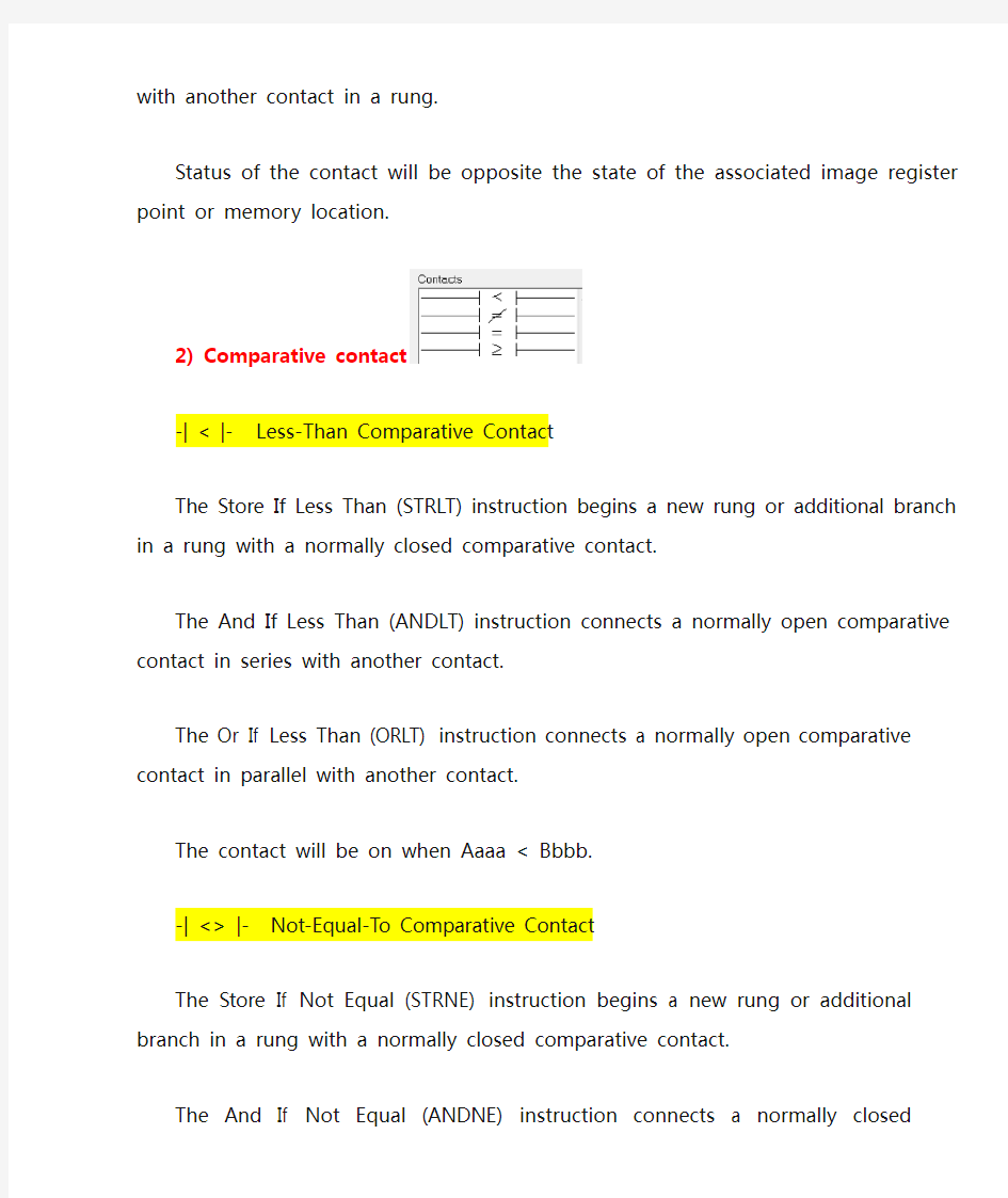
2) Comparative contact
-| < |- Less-Than Comparative Contact
The Store If Less Than (STRLT) instruction begins a new rung or additional branch in a rung with a normally closed comparative contact.
The And If Less Than (ANDLT) instruction connects a normally open comparative contact in series with another contact.
The Or If Less Than (ORLT) instruction connects a normally open comparative contact in parallel with another contact.
The contact will be on when Aaaa < Bbbb.
normally closed comparative contact.
The And If Not Equal (ANDNE) instruction connects a normally closed comparative contact in series with another contact.
The Or If Not Equal (ORNE) instruction connects a normally closed comparative contact in parallel with another contact.
The contact will be on when Aaaa <> Bbbb.
-| = |- Equal-To Comparative Contact
The Store If Equal (STRE) instruction begins a new rung or additional branch in a rung with a normally open comparative contact.
The And If Equal (ANDE) instruction connects a normally open comparative contact in series with another contact.
The Or If Equal (ORE) instruction connects a normally open comparative contact in parallel with another contact.
The contact will be on when Aaaa = Bbbb.
-| >= |- Greater-Than-Or-Equal-To Comparative Contact
The Store If Greater Than Or Equal (STRGE) instruction begins a new rung or additional branch in a rung with a normally open comparative contact.
The And If Greater Than Or Equal (ANDGE) instruction connects a normally open comparative contact in series with another contact.
The Or If Greater Than Or Equal (ORGE) instruction connects a normally open comparative contact in parallel with another contact.
The contact will be on when Aaaa >= Bbbb.
3) Program control
NOT - Not Instruction
The Not instruction inverts the status of the rung at the point of the instruction.
4) Immediate I/O
-| I |- Immediate Contact
The Store Immediate (STRI) instruction begins a new rung or additional branch in a rung.
The Or Immediate (ORI) instruction connects two contacts in parallel.
The status of the contact will be the same as the status of the associated input point on the module at the time the instruction is executed. The image register is not updated.
-| I/ |- Immediate Not Contact
The Store Not Immediate (STRNI) instruction begins a new rung or additional branch in a rung.
The And Not Immediate (ANDNI) instruction connects two contacts in series.
The Or Not Immediate (ORNI) instruction connects two contacts in parallel.
The status of the contact will be opposite the status of the associated input point on the module at the time the instruction is executed. The image register is not updated.
5) Differential
-| _|?|- Positive Differential Contact
The Store Positive Differential (STRPD) instruction begins a new rung or additional branch in a rung.
The And Positive Differential (ANDPD) instruction connects two contacts in series.
The Or Positive Differential (ORPD) instruction connects two contacts in parallel.
This is a leading edge triggered one-shot contact. When the corresponding memory location transitions from low to high, the contact comes on for one CPU scan.
-| 瘄_ |- Negative Differential Contact
The Store Negative Differential (STRND) instruction begins a new rung or additional branch in a rung.
The And Negative Differential (ANDND) instruction connects two contacts in series.
The Or Negative Differential (ORND) instruction connects two contacts in parallel.
This is a trailing edge triggered one-shot contact. When the corresponding memory location transitions from high to low, the contact comes on for one CPU scan.
2. Coil
1) Standard coil
output. Multiple Or Out instructions referencing the same output coil may be used, since all contacts controlling the output are ored together. If the status of any rung is on, the output will also be on. OUT - Out Coil
The Out instruction reflects the status of the rung (on/off) and outputs the discrete (on/off) state to the specified image register point or memory location. Multiple Out instructions referencing the same discrete location should not be used since only the last Out instruction in the program will control the physical output point. See Or Out (OROUT).
PD - Positive Differential Coil
The Positive Differential instruction is typically known as a one shot. When the input logic produces an off to on transition, the output will energize for one CPU scan.
RST - Reset Coil
The Reset instruction resets or turns off an image register point/memory location or a range of image registers points/memory locations. Once the point/location is reset it is not necessary for the input to remain on.
SET - Set Coil
The Set instruction sets or turns on an image register point/memory location or a consecutive range of image register points/memory locations. Once the point/location is set it will remain on until it is reset using the Reset (RST) instruction. It is not necessary for the input controlling the Set instruction to remain on.
2) RLL plus
CVJMP - Converge Jump Coil
The Converge Stage instruction is used to group certain stages together by defining them as Converge Stages. When all of the Converge Stages within a group become active, the CVJMP instruction will execute. All Converge Stages are deactivated one scan after the CVJMP instruction is executed.
Additional logic instructions are only allowed following the last Converge Stage instruction and before the CVJMP instruction. Multiple CVJMP instructions are allowed. Converge Stages must be programmed in the main body of the application program. This means they cannot be programmed in Subroutines or Interrupt Routines.
JMP - Jump to Stage Coil
The Jump instruction allows the program to transition from an active stage which contains the jump instruction to another stage which is specified in the instruction. The jump will occur when the input logic is true. The active stage that contains the Jump will be deactivated 1 scan after the Jump instruction is executed.
NJMP - Not Jump Coil
The Not Jump instruction allows the program to transition from an active stage which contains the jump instruction to another which is specified in the instruction. The jump will occur when the input logic is off. The active stage that contains the Not Jump will be deactivated 1 scan after the Not Jump
3) Program control
END - End Coil
The End instruction marks the termination point of the normal program scan. An End instruction is required at the end of the main program body. If the End instruction is omitted an error will occur and the CPU will not enter the Run Mode. Data labels, subroutines and interrupt routines are placed after the End instruction. The End instruction is not conditional; therefore, no input contact is allowed.
FOR - For Coil (used with NEXT Coil)
The For and Next instructions are used to execute a section of ladder logic between the For and Next instructions a specified number of times. When the For instruction is enabled, the program will loop the specified number of times. If the For instruction is not energized the section of ladder logic between the For and Next instructions is not executed.
For / Next instructions cannot be nested. The normal I/O update and CPU housekeeping is suspended while executing the For / Next loop. The program scan can increase significantly, depending on the amount of times the logic between the For and Next instruction is executed. With the exception of immediate I/O instructions, I/O will not be updated until the program execution is completed for that scan. Depending on the time required to complete the program execution, it may be necessary to reset the watch dog timer inside of the For / Next loop using the RSTWT instruction.
GTS - Go To Subroutine Coil (used with SBR Box)
The Goto Subroutine instruction allows a section of ladder logic to be placed outside the main body of the program to execute only when needed. The GTS instructions can be nested up to 8 levels.
Typically this will be used in an application where a block of program logic may be slow to execute and is not required to execute every scan. The subroutine label and all associated logic is placed after the End statement in the program. When the subroutine is called from the main program, the CPU will execute the subroutine (SBR) with the same constant number (K) as the GTS instruction which called the subroutine.
By placing code in a subroutine it is only scanned and executed when needed since it resides after the End instruction. Code which is not scanned does not impact the overall scan time of the program.
MLR - Master Line Reset Coil
The Master Line Reset instruction marks the end of control for the corresponding MLS instruction. The MLR reference is one less than the corresponding MLS.
The Master Line Set (MLS) and Master Line Reset (MLR) instructions allow you to quickly enable
MLS - Master Line Set Coil
The Master Line Set instruction allows the program to control sections of ladder logic by forming a new power rail controlled by the main left power rail. The main left rail is always master line 0. When a MLS K1 instruction is used, a new power rail is created at level 1. Master Line Sets and Master Line Resets can be used to nest power rails up to seven levels deep.
The Master Line Set (MLS) and Master Line Reset (MLR) instructions allow you to quickly enable (or disable) sections of the RLL program. This provides program control flexibility.
NEXT - Next Coil (used with FOR Coil)
The For and Next instructions are used to execute a section of ladder logic between the For and Next instructions a specified number of times. When the For instruction is enabled, the program will loop the specified number of times. If the For instruction is not energized the section of ladder logic between the For and Next instructions is not executed.
For / Next instructions cannot be nested. The normal I/O update and CPU housekeeping is suspended while executing the For / Next loop. The program scan can increase significantly, depending on the amount of times the logic between the For and Next instruction is executed. With the exception of immediate I/O instructions, I/O will not be updated until the program execution is completed for that scan. Depending on the time required to complete the program execution, it may be necessary to reset the watch dog timer inside of the For / Next loop using the RSTWT instruction.
NOP - No Operation Coil
The No Operation is an empty (not programmed) memory location.
PAUSE - Pause Coil
The Pause instruction disables the output update on a range of outputs. The ladder program will continue to run and update the image register, however the outputs in the range specified in the Pause instruction will be turned off at the output module.
RSTWT - Reset Watch Dog Timer Coil
The Reset Watch Dog Timer instruction resets the CPU scan timer. The default setting for the watch dog timer is 200ms. However, for/next loops, subroutines, interrupt routines, and table instructions can be programmed such that the scan becomes longer than 200ms. When instructions are used in a manner that could exceed the watch dog timer setting, this instruction can be used to reset the timer.
A software timeout error (E003) will occur and the CPU will enter the program mode if the scan time exceeds the watch dog timer setting. Placement of the RSTWT instruction is very important. It must be executed before the scan time exceeds the watch dog timer's setting.
If the scan time is consistently longer than the watch dog timer's setting, the timeout value may be permanently increased in the Watch Dog Timer dialog box under the PLC/Setup menu. This eliminates the need for the RSTWT instruction.
RT - Return From Subroutine Coil
When a Subroutine Return is executed in the subroutine the CPU will return to the point in the main
input contact on the rung).
RTC - Conditional Return From Subroutine Coil
The Subroutine Return Conditional instruction is an optional instruction used with an input contact to implement a conditional return from the subroutine. The Subroutine Return (RT) is still required for termination of the Subroutine.
STOP - Stop Coil
The Stop instruction changes the operational mode of the CPU from Run to Program (Stop) mode. This instruction is typically used to stop PLC operation in a shutdown condition such as a I/O module failure.
4) Interrupt
DISI - Disable Interrupts Coil
The Disable Interrupt instruction is programmed in the main body of the application program (before the End instruction) to disable both hardware or software interrupts. Once the coil has been energized interrupts will be disabled until the interrupt is enabled by the Enable Interrupt (ENI) instruction.
ENI - Enable Interrupts Coil
The Enable Interrupt instruction is programmed in the main body of the application program (before the End instruction) to enable hardware or software interrupts. Once the coil has been energized interrupts will be enabled until the interrupt is disabled by the Disable Interrupt (DISI) instruction.
IRT - Return From Interrupt Coil
When an Interrupt Return is executed in the interrupt routine the CPU will return to the point in the main body of the program from which it was called. The Interrupt Return is programmed as the last instruction in an interrupt routine and is a stand alone instruction (no input contact on the rung).
IRTC - Conditional Return From Interrupt Coil
The Interrupt Return Conditional instruction is an optional instruction used with an input contact to implement a conditional return from the interrupt routine. The Interrupt Return (IRT) is still required to terminate the interrupt routine.
5) Immediate I/O
OROUTI - Immediate Or Out Coil
The Or Out Immediate instruction has been designed to use more than 1 rung of discrete logic to
time the instruction is executed, the output will also be on.
OUTI - Immediate Out Coil
The Out Immediate instruction reflects the status of the rung (on/off) and outputs the discrete (on/off) status to the specified module output point and the image register at the time the instruction is executed. If multiple Out Immediate instructions referencing the same discrete point are used it is possible for the module output status to change multiple times in a CPU scan. See Or Out Immediate (OROUTI).
RSTI - Reset Immediate Coil
The Reset Immediate instruction immediately resets, or turns off an output or a range of outputs in the image register and the output module(s) at the time the instruction is executed. Once the outputs are reset it is not necessary for the input to remain on.
SETI - Set Immediate Coil
The Set Immediate instruction immediately sets, or turns on an output or a range of outputs in the image register and the corresponding output module(s) at the time the instruction is executed. Once the outputs are set it is not necessary for the input to remain on. The Reset Immediate (RSTI) instruction can be used to reset the outputs.
3. BOX
1) Accumulator/stack
LD - Load Box
The Load instruction is a 16 bit instruction that loads the value (Aaaa), which is either a V memory location or a 4 digit constant, into the lower 16 bits of the accumulator. The upper 16 bits of the accumulator are set to 0.
SP76: On when the value loaded into the accumulator by any instruction is zero.
NOTE: Two consecutive Load instructions will place the value of the first load instruction onto the accumulator stack.
LDA - Load Address Box
The Load Address instruction is a 16 bit instruction. It converts any octal value or address to the equivalent HEX value and loads the HEX value into the accumulator. This instruction is useful when an address parameter is required since all addresses for the 105/205/350/405 PLCs are in octal.
SP76: On when the value loaded into the accumulator by any instruction is zero.
accumulator stack.
LDD - Load Double Box
The Load Double instruction is a 32 bit instruction that loads the value (Aaaa), which is either two consecutive V memory locations or an 8 digit constant value, into the accumulator.
SP76: On when the value loaded into the accumulator by any instruction is zero.
NOTE: Two consecutive Load instructions will place the value of the first load instruction onto the accumulator stack.
LDF - Load Formatted Box
The Load Formatted instruction loads 1-32 consecutive bits from discrete memory locations into the accumulator. The instruction requires a starting location (Aaaa) and the number of bits (Kbbb) to be loaded. Unused accumulator bit locations are set to zero.
SP76: On when the value loaded into the accumulator by any instruction is zero.
NOTE: Two consecutive Load instructions will place the value of the first load instruction onto the accumulator stack.
OUT - Output Box
The Out instruction is a 16 bit instruction that copies the value in the lower 16 bits of the accumulator to a specified V memory location (Aaaa).
OUTD - Output Double Box
The Out Double instruction is a 32 bit instruction that copies the value in the accumulator to two consecutive V memory locations at a specified starting location (Aaaa).
OUTF - Output Formatted Box
The Out Formatted instruction outputs 1-32 bits from the accumulator to the specified discrete memory locations. The instruction requires a starting location (Aaaa) for the destination and the number of bits (Kbbb) to be output.
POP - Pop From Stack Box
The Pop instruction moves the value from the first level of the accumulator stack (32 bits) to the accumulator and shifts each value in the stack up one level.
SP63: On when the result of the instruction causes the value in the accumulator to be zero.
2) Bit
DECO - Decode Box
The Decode instruction decodes a 5 bit binary value of 0-31 (0-1F HEX) in the accumulator by setting the appropriate bit position to a 1. If the accumulator contains the value F (HEX), bit 15 will be set in the accumulator. If the value to be decoded is greater than 31, the number is divided by 32 until the value is less than 32 and then the value is decoded.
ENCO - Encode Box
The Encode instruction encodes the bit position in the accumulator having a value of 1, and returns the appropriate binary representation. If the most significant bit is set to 1 (Bit 31), the Encode instruction will place the value HEX 1F (decimal 31) in the accumulator. If the value to be encoded is 0000 or 0001, the instruction will place a zero in the accumulator. If the value to be encoded has more than one bit position set to a "1", the least significant "1" will be encoded and SP53 will be set on.
SHFL - Shift Left Box
Shift Left is a 32 bit instruction that shifts the bits in the accumulator a specified number (Aaaa) of places to the left. The vacant positions are filled with zeros and the bits shifted out of the accumulator are lost.
SHFR - Shift Right Box
Shift Right is a 32 bit instruction that shifts the bits in the accumulator a specified number (Aaaa) of places to the right. The vacant positions are filled with zeros and the bits shifted out of the accumulator are lost.
SUM - Sum Box
The Sum instruction counts number of bits that are set to "1" in the accumulator. The HEX result resides in the accumulator.
The Date instruction can be used to set the date in the CPU. The instruction requires two consecutive V memory locations to set the date. If the values in the specified locations are not valid, the date will not be set.
The current date can be read from 4 consecutive V memory locations (V7771-V7774):
V7774 - Year (0-99) V7773 - Month (0-12) V7772 - Day (0-31) V7771 - Day of Week (0-06) The values entered for the day of week are: 0=Sunday, 1=Monday, 2=Tuesday, 3=Wednesday, 4=Thursday, 5=Friday, 6=Saturday
TIME - Hour, Seconds, and Minutes Box
The Time instruction can be used to set the time (24 hour clock) in the CPU. The instruction requires two consecutive V memory locations which are used to set the time. If the values in the specified locations are not valid, the time will not be set. The current time can be read from memory locations V7747 and V7766-V7770:
V7747 - 1/100 seconds (10ms) (0-99) V7766 - Seconds (0-59) V7767 - Minutes (0-59) V7770 - Hour (0-23)
4) Conversion
ATH - ASCII To Hex Conversion Box
The ASCII To HEX instruction converts a table of ASCII values to a specified table of HEX values. ASCII values are two digits and their HEX equivalents are one digit. So an ASCII table of four V memory locations would only require two V memory locations for the equivalent HEX table. Below are the steps to program an ASCII to HEX table function:
Step 1: Load the number of V memory locations for the ASCII table into the first level of the accumulator stack.
Step 2: Load the starting V memory location for the ASCII table into the accumulator. This parameter must be HEX.
Step 3: Specify the starting V memory location (Vaaa) for the HEX table in the ATH instruction.
BCD - Convert To Binary Coded Decimal Box
The Binary Coded Decimal instruction converts a binary value in the accumulator to a BCD value. The result resides in the accumulator.
The Binary instruction converts a BCD value in the accumulator to the equivalent binary value. The result resides in the accumulator.
GRAY - Gray Code to BCD Box
The Gray code instruction converts a 16 bit gray code value to a BCD value. The BCD conversion requires 10 bits of the accumulator. The upper 22 bits are set to "0". This instruction is designed for use with devices (typically encoders) that use the gray code numbering scheme. The Gray Code instruction will directly convert a gray code number to a BCD number for devices having a resolution of 512 or 1024 counts per revolution. If a device having a resolution of 360 counts per revolution is to be used you must subtract a BCD value of 76 from the converted value to obtain the proper result. For a device having a resolution of 720 counts per revolution you must subtract a BCD value of 152.
HTA - Hex To ASCII Box
The HEX to ASCII instruction converts a table of HEX values to a specified table of ASCII values. HEX values are one digit and their ASCII equivalents are two digits. So a HEX table of two V memory locations would require four V memory locations for the equivalent ASCII table. Below are the steps to program a HEX to ASCII table function:
Step 1: Load the number of V memory locations in the HEX table into the first level of the accumulator stack.
Step 2: Load the starting V memory location for the HEX table into the accumulator. This parameter must be HEX.
Step 3: Specify the starting V memory location (Vaaa) for the ASCII table in the HTA instruction.
INV - Inverse (One's Complement) Box
The Invert instruction inverts or takes the one's complement of the 32 bit value in the accumulator. The result resides in the accumulator.
SFLDGT - Shuffle Digits Box
The Shuffle Digits instruction shuffles a maximum of 8 digits rearranging them in a specified order. Below are the steps to use the shuffle digit function:
Step 1: Load the value (digits) to be shuffled into the first level of the accumulator stack.
Step 2: Load the order the digits will be shuffled to into the accumulator.
Note: If the number used to specify the order contains a 0 or 9-F, the corresponding position will be set to 0.
Note: If the number used to specify the order contains duplicate numbers, the most significant duplicate number is valid. The result resides in the accumulator.
Step 3: Insert the SFLDGT instruction.
5) Drum sequencing
DRUM - Timed Drum with Discrete Outputs
The time driven drum has up to 16 steps and 16 discrete output points.
Output status is written to the appropriate output during each step.
Specify a time base per count (in milliseconds). Each step can have a different number of counts to trigger the transition to the next step.
Also define preset step as destination when reset occurs.
EDRUM - Time and Event Drum with Discrete Outputs
The time and/or event driven drum has up to 16 steps and 16 discrete output points.
Output status is written to the appropriate output during each step.
Specify a time base per count (in milliseconds). Each step can have a different number of counts and an event to trigger the counting. Once the time has expired, a transition to the next step occurs.
Also define preset step as destination when reset occurs.
6) IBox 200 Memory
Moved IB-201
Move Double Word moves a double word to two consecutive memory locations directly or indirectly via a pointer, either as a double HEX constant, from a double memory location, or indirectly through a pointer to a double memory location.
Movew IB-200
Move Single Word moves a word to a memory location directly or indirectly via a pointer, either as a HEX constant, from a memory location, or indirectly through a pointer
7) IBox 300 Discreet Helper
OFFDTMR IB-302
Off Delay Timer will delay the "turning off" of the Output parameter by the specified Off Delay Time (in hundredths of a second) based on the power flow into the IBox. Once the IBox receives power, the Output bit will turn On immediately. When the power flow to the IBox turns Off, the Output bit WILL REMAIN ON for the specified amount of time (in hundredths of a second). Once the Off Delay Time has expired, the output will turn Off. If the power flow to the IBox comes back on BEFORE the Off Delay Time, then the timer is RESET and the Output will remain On - so you must continuously have NO power flow to the IBox for AT LEAST the specified Off Delay Time before the Output will turn Off.
This IBox utilizes a Timer resource (TMRF), which cannot be used anywhere else in your program.
ONDTMR IB-301
On Delay Timer will delay the "turning on" of the Output parameter by the specified amount of time (in hundredths of a second) based on the power flow into the IBox. Once the IBox loses power, the Output is turned off immediately. If the power flow turns off BEFORE the On Delay Time, then the timer is RESET and the Output is never turned on, so you must have continuous power flow to the IBox for at least the specified On Delay Time before the Output turns On.
This IBox utilizes a Timer resource (TMRF), which cannot be used anywhere else in your program.
ONESHOT IB-303
One Shot will turn on the given bit output parameter for one scan on an OFF to ON transition of the power flow into the IBox. This IBox is simply a different name for the PD Coil (Positive Differential).
PONOFF IB-300
Push On/Push OFF Circuit toggles an output state whenever its input power flow transitions from off to on. Requires an extra bit parameter for scan-to-scan state information. This extra bit must NOT be used anywhere else in the program.
ANLGCMB IB-462
Analog Input/Output Combo Module Pointer Setup generates the logic to configure the pointer method for one analog input/output combo module on the first PLC scan following a Program to Run transition.
This IBox determines the System V Data Type and Pointer addresses based on the CPU type, the Base#, and the Slot#.
The Input Data Address is the starting location in User V memory for where the analog input data values will be written, one location for each input channel enabled.
The Output Data Address is the starting location in User V memory for where the analog output data values will be read, one location for each output channel enabled.
Since this logic only executes on the first scan, this IBox cannot have any input logic.
ANLGIN IB-460
Analog Input Module Pointer Setup generates the logic to configure the pointer method for one analog input module on the first PLC scan following a Program to Run transition.
This IBox determines the System V Data Type and Pointer addresses based on the CPU type, the Base#, and the Slot#.
The Input Data Address is the starting location in User V memory for where the analog input data values will be written, one location for each input channel enabled.
Since this logic only executes on the first scan, this IBox cannot have any input logic.
ANLGOUT IB-461
Analog Output Module Pointer Setup generates the logic to configure the pointer method for one analog output module on the first PLC scan following a Program to Run transition.
This IBox determines the System V Data Type and Pointer addresses based on the CPU type, the Base#, and the Slot#.
The Output Data Address is the starting location in User V memory for where the analog output data values will be read, one location for each output channel enabled.
Since this logic only executes on the first scan, this IBox cannot have any input logic.
ANSCL IB-423
Analog Scale 12 Bit BCD to BCD Engineering Units scales a 12 bit BCD analog value (0-4095 BCD) into BCD engineering units. You specify the engineering unit high value (when raw is 4095), and the engineering low value (when raw is 0), and the output V memory address you want the to place the scaled engineering unit value. The engineering units are generated as BCD and can be the full range of 0 to 9999 (see ANSCLB - Analog Scale 12 Bit Binary to Binary if your raw units are in Binary
Note that this IBox only works with unipolar unsigned raw values. It does NOT work with bipolar or sign plus magnitude raw values.
ANSCLB IB-403
Analog Scale 12 Bit Binary to Binary Engineering Units scales a 12 bit binary analog value (0-4095 decimal) into binary (decimal) engineering units. You specify the engineering unit high value (when raw is 4095), and the engineering low value (when raw is 0), and the output V memory address you want to place the scaled engineering unit value. The engineering units are generated as binary and can be the full range of 0 to 65535 (see ANSCL - Analog Scale 12 Bit BCD to BCD if your raw units are in BCD format).
Note that this IBox only works with unipolar unsigned raw values. It does NOT work with bipolar, sign plus magnitude, or signed 2's complement raw values.
FILTER IB-422
Filter Over Time in BCD format will perform a first-order filter on the Raw Data on a defined time interval. The equation is
New = Old + [(Raw - Old) / FDC] where
New: New Filtered Value
Old: Old Filtered Value
FDC: Filter Divisor Constant
Raw: Raw Data
Filter Divisor Constant is an integer in the range K1 to K100, such that if it equaled K1 then no filtering would be done.
The rate at which the calculation is performed is specified by time in hundredths of a second (0.01 seconds) as the Filter Freq Time parameter. Note that this Timer instruction is embedded in the IBox and must NOT be used anywhere else in your program. Power flow controls whether the calculation is enabled. If it is disabled, the Filter Value is not updated. On the first scan from Program to Run mode, the Filter Value is initialized to 0 to give the calculation a consistent starting point.
FILTERB IB-402
Filter Over Time in Binary (decimal) format will perform a first-order filter on the Raw Data on a defined time interval. The equation is
New = Old + [(Raw - Old) / FDC] where
New: New Filtered Value
Old: Old Filtered Value
FDC: Filter Divisor Constant
Raw: Raw Data
Filter Divisor Constant is an integer in the range K1 to K100, such that if it equaled K1 then no filtering would be done.
The rate at which the calculation is performed is specified by time in hundredths of a second (0.01
enabled. If it is disabled, the Filter Value is not updated. On the first scan from Program to Run mode, the Filter Value is initialized to 0 to give the calculation a consistent starting point.
HILOAL IB-421
Hi/Low Alarm - BCD format monitors a BCD V memory location and sets four possible alarm states, High-High, High, Low, and Low-Low whenever the IBox has power flow. You enter the alarm thresholds as constant K BCD values (K0-K9999) and/or BCD V memory locations.
You must ensure that threshold limits are valid, that is HH >= H > L >= LL. Note that when the High-High or Low-Low alarm condition is true, that the High and Low alarms will also be set, respectively. This means you may use the same threshold limit and same alarm bit for the High-High and the High alarms in case you only need one "High" alarm. Also note that the boundary conditions are inclusive. That is, if the Low boundary is K50, and the Low-Low boundary is K10, and if the Monitoring Value equals 10, then the Low Alarm AND the Low-Low alarm will both be ON. If there is no power flow to the IBox, then all alarm bits will be turned off regardless of the value of the Monitoring Value parameter.
HILOALB IB-401
Hi/Low Alarm - Binary format monitors a binary (decimal) V memory location and sets four possible alarm states, High-High, High, Low, and Low-Low whenever the IBox has power flow. You enter the alarm thresholds as constant K decimal values (K0-K65535) and/or binary (decimal) V memory locations.
You must ensure that threshold limits are valid, that is HH >= H > L >= LL. Note that when the High-High or Low-Low alarm condition is true, that the High and Low alarms will also be set, respectively. This means you may use the same threshold limit and same alarm bit for the High-High and the High alarms in case you only need one "High" alarm. Also note that the boundary conditions are inclusive. That is, if the Low boundary is K50, and the Low-Low boundary is K10, and if the Monitoring Value equals 10, then the Low Alarm AND the Low-Low alarm will both be ON. If there is no power flow to the IBox, then all alarm bits will be turned off regardless of the value of the Monitoring Value parameter.
9) Ibox 500: Math
MATHBCD IB-521
Math - BCD Format lets you enter complex mathematical expressions like you would in Visual Basic,
functions - Convert to BCD (BCD), Convert to Binary (BIN), BCD Complement (BCDCPL), Convert from Gray Code (GRAY), Invert Bits (INV), and BCD/HEX to Seven Segment Display (SEG).
Example: ((V2000 + V2001) / (V2003 - K100)) * GRAY(V3000 & K001F)
Every V memory reference MUST be to a single word BCD formatted value. Intermediate results can go up to 32 bit values, but as long as the final result fits in a 16 bit BCD word, the calculation is valid. Typical example of this is scaling using multiply then divide, (V2000 * K1000) / K4095. The multiply term most likely will exceed 9999 but fits within 32 bits. The divide operation will divide 4095 into the 32-bit accumulator, yielding a result that will always fit in 16 bits.
You can reference binary V memory values by using the BCD conversion function on a V memory location but NOT an expression. That is BCD(V2000) is okay and will convert V2000 from Binary to BCD, but BCD(V2000 + V3000) will add V2000 as BCD, to V3000 as BCD, then interpret the result as Binary and convert it to BCD - NOT GOOD.
Also, the final result is a 16 bit BCD number and so you could do BIN around the entire operation to store the result as Binary.
MATHBIN IB-501
Math - Binary Format lets you enter complex mathematical expressions like you would in Visual Basic, Excel, or C++ to do complex calculations, nesting parentheses more than 4 levels deep. In addition to + - * /, you can do Modulo (% aka Remainder), Shift Right (>>) and Shift Left (<<), Bit-wise And (&) Or (|) Xor (^), and some binary functions - Convert to BCD (BCD), Convert to Binary (BIN), Decode Bits (DECO), Encode Bits (ENCO), Invert Bits (INV), HEX to Seven Segment Display (SEG), and Sum Bits (SUM).
Example: ((V2000 + V2001) / (V2003 - K10)) * SUM(V3000 & K001F)
Every V memory reference MUST be to a single word binary formatted value. Intermediate results can go up to 32 bit values, but as long as the final result fits in a 16 bit binary word, the calculation is valid. Typical example of this is scaling using multiply then divide, (V2000 * K1000) / K4095. The multiply term most likely will exceed 65535 but fits within 32 bits. The divide operation will divide 4095 into the 32-bit accumulator, yielding a result that will always fit in 16 bits.
You can reference BCD V memory values by using the BIN conversion function on a V memory location but NOT an expression. That is BIN(V2000) is okay and will convert V2000 from BCD to Binary, but BIN(V2000 + V3000) will add V2000 as Binary, to V3000 as Binary, then interpret the result as BCD and convert it to Binary - NOT GOOD.
Also, the final result is a 16 bit binary number and so you could do BCD around the entire operation to store the result as BCD.
SQUARE IB-523
Square BCD Format squares the given 4-digit WORD BCD number and writes it in as an 8-digit
SQUAREB IB-503
Square Binary Format squares the given 16-bit WORD Binary number and writes it as a 32-bit DWORD Binary result.
SUMBCD IB-522
Sum BCD Numbers sums up a list of contiguous 4-digit WORD BCD numbers into an 8-digit DWORD BCD result.
You specify the group's starting and ending V memory addresses (inclusive). When enabled, this instruction will add up all the numbers in the group (so you may want to place a differential contact driving the enable).
SUMBCD could be used as the first part of calculating an average.
SUMBIN IB-502
Sum Binary Numbers sums up a list of contiguous 16-bit WORD Binary numbers into a 32-bit DWORD result.
You specify the group's starting and ending V memory addresses (inclusive). When enabled, this instruction will add up all the numbers in the group (so you may want to place a differential contact driving the enable).
SUMBIN could be used as the first part of calculating an average.
10)ibox 700:communications
ECDHCPD IB-736
ECOM100 Disable DHCP will setup the ECOM100 to use its internal TCP/IP settings on a leading edge transition to the IBox. To configure the ECOM100's TCP/IP settings manually, use the NetEdit3 utility, or you can do it programmatically from your PLC program using the ECOM100 IP Setup (ECIPSUP), or the individual ECOM100 IBoxes: ECOM Write IP Address (ECWRIP), ECOM Write Gateway Address (ECWRGWA), and ECOM100 Write Subnet Mask (ECWRSNM).
The Workspace parameter is an internal, private register used by this IBox and MUST BE UNIQUE in this one instruction and MUST NOT be used anywhere else in your program.
Either the Success or Error bit parameter will turn on once the command is complete. If there is an error, the Error Code parameter will report an ECOM100 error code (less than 100), or a PLC logic error (greater than 1000).
will disable the ECOM100 module for at least a half second until it writes the Flash-ROM. Therefore, it is HIGHL Y RECOMMENDED that you only execute this IBox ONCE, on first scan. Since it requires a LEADING edge to execute, use a NORMALL Y CLOSED SP0 (STR NOT First Scan) to drive the power flow to the IBox.
In order for this ECOM100 IBox to function, you must turn ON dip switch 7 on the ECOM100 circuit board.
ECDHCPE IB-735
ECOM100 Enable DHCP will tell the ECOM100 to obtain its TCP/IP setup from a DHCP Server on a leading edge transition to the IBox.
The IBox will be successful once the ECOM100 has received its TCP/IP settings from the DHCP server. Since it is possible for the DHCP server to be unavailable, a Timeout parameter is provided so that the IBox can complete, but with an Error (Error Code = 1004 decimal).
See also the ECOM100 IP Setup (ECIPSUP) IBox 717 to directly setup ALL of the TCP/IP parameters in a single instruction - IP Address, Subnet Mask, and Gateway Address.
The Workspace parameter is an internal, private register used by this IBox and MUST BE UNIQUE in this one instruction and MUST NOT be used anywhere else in your program.
Either the Success or Error bit parameter will turn on once the command is complete. If there is an error, the Error Code parameter will report an ECOM100 error code (less than 100), or a PLC logic error (greater than 1000).
The "Enable DHCP" setting is stored in Flash-ROM in the ECOM100 and the execution of this IBox will disable the ECOM100 module for at least a half second until it writes the Flash-ROM. Therefore, it is HIGHL Y RECOMMENDED that you only execute this IBox ONCE, on first scan. Since it requires a LEADING edge to execute, use a NORMALL Y CLOSED SP0 (STR NOT First Scan) to drive the power flow to the IBox.
In order for this ECOM100 IBox to function, you must turn ON dip switch 7 on the ECOM100 circuit board.
ECDHCPQ IB-734
ECOM100 Query DHCP Setting will determine if DHCP is enabled in the ECOM100 on a leading edge transition to the IBox. The DHCP Enabled bit parameter will be ON if DHCP is enabled, OFF if disabled.
The Workspace parameter is an internal, private register used by this IBox and MUST BE UNIQUE in this one instruction and MUST NOT be used anywhere else in your program.
Either the Success or Error bit parameter will turn on once the command is complete.
In order for this ECOM100 IBox to function, you must turn ON dip switch 7 on the ECOM100 circuit