机械毕业设计英文外文翻译研磨机的最佳优化设计
附录一
研磨机的最佳优化设计
摘要:研磨机的制造商正在尽量的减少传动给低振动,高生产率的研磨机所增加的压力。然而,实际上,运行研磨的过度磨损的发生,研磨孔附近的裂缝的发展都可能带来脱离的破碎和造成灾难性的结果。振动等级的增加已经在很多的新型研磨机中有所发现。现有的设计方法对于这种现象的解释是不可靠的。本文能够表述一种新的研磨机的设计方法,并写能够很好的阻碍振动的增加和不必要的磨损。最后,提供了研磨机的较好的设计方法。
关键字:研磨机过度磨损破碎振动新设计
标注单位
C 联结的扭力硬度
F离心力
cf
F惯性力
1
J滑块惯性
J电动马达转子的两极滑块的惯性
1
J研磨机的两极滑块的惯性
2
,k k径向支持的硬度
12
K动能
l研磨区和引力的中心之间的距离
L径向支持的距离
m研磨齿或槌集合重量
M瞬时惯性
i
p槌的频率交换振动
P潜在能量
Q推力
i
R圆盘的半径
W重量
x槌的引力中心的换置
c
,x x鼓轮轴支持的换置
12
φ侧轴或槌的坐标的角度换置
ψ圆盘的坐标角度
ω初始频率
ω鼓轮的旋转速度
o
12,ωω 研磨的扭力震动的天然频率磨细传输
一 介绍
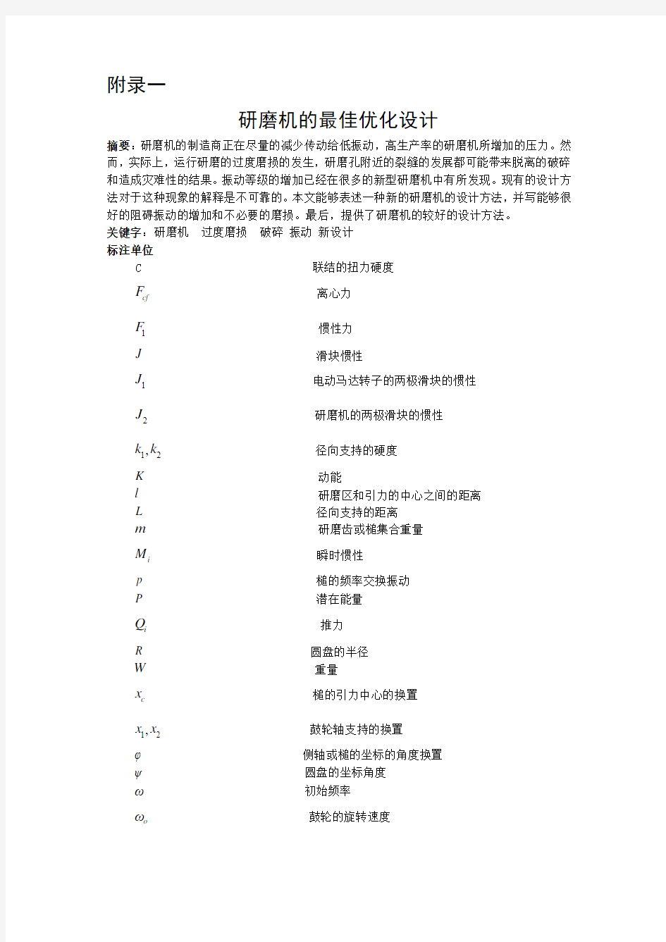
研磨机广泛地被用于食物和谷粒工业。研磨机的一个典型结构被显示在图 1.它由一个电动马达所组成 (1),这个马达带动鼓轮联结(2)。鼓轮包括一个圆盘(3)在轮轴上转动。(4)轮轴靠两个径向支撑所支持。(5)它有二组杆: 一组杆(6)运送槌,而另一组杆(7)运送缓冲装置。它们用来限制那槌摇摆按某一角度转动。(8)槌被聚集在一个杆上(6),举例来说五支槌,然后四支槌,在圆盘的相反边上的等等,不同的槌被安装( 举例来说在一边上有五个,在另一边上则有四个).那槌在外形上是矩形的并且有三个外部的边缘被焊接在材料表面上面。他们被间隔的装置所分开。
在研磨机被安置好之前,这个装置是通过增加自己的重量来保持平衡的。一些公司甚至选择槌以便它的总重量装置在一支杆对所有的杆是相同的。
整个的结构集合在一个金属包装中被附上( 不在图 1 中显示).被供应的谷物在包装的顶端打开。替换槌击中落下的谷粒, 打碎它,并且磨细了碎片在包装的底部从滑槽被收集。鼓旋转的方向时常被颠倒用以证实槌的边缘的磨损。在研磨机的操作中, 杆所连接的槌没有与谷粒的直接接触或磨细碎片, 因为那个杆被槌及其周围空间包围。 与此同时,周围空间的外部表面在与磨细的碎片直接的接触中,不表示任何磨平的警告。
在实际中,严格的震动通常发生在相对较新的研磨机上。 深的裂缝在圆盘上通常会发展到洞附近。 裂缝以 45 度被定向到半径和向圆盘的周边部份 (见到图 2),可能会造成脱离破碎的危险。不平顺的穿越在槌的竿上发生。深的凹槽在圆筒形的表面上发展到杆上.(见到图 3) 槌上的洞会逐渐的变为椭圆形这是由于圆形的边缘。 槌的两侧表面在这个洞的附近会有一个冲击负荷力来警示从其间隔中所具有的装置。
在槌上的离心力要比圆盘上的应力小上好几倍。 竿上的凹槽和槌上的椭圆形洞证明实际的连络压迫力超过生产压迫力,并且在槌上边缘的冲击标志表明那槌正在被摇动和旋转。现有的设计方法已经证明和解释这一种现象的不可能性。 要减少震动的程度,人们不得不减
少鼓的旋转工作速度, 而这样做必将会影响到生产效率。
2 对于传统研磨机的弱表现力的理论解释和存在的问题
当一个研磨机被装配的时候, 通常36个槌以一种盘环的样式被安装在一个杆上。由于槌有不同的组成部分,因此,槌的分配沿着杆是不平顺的。当鼓快速旋转的时候,离心力会沿着半径指向槌。由于不平顺的槌的分配和槌的交错打在地面上 (五个槌在圆盘直径的一边上而另外的四个槌则在相反的方向上),由于离心力的分配不均发生,这将引起整个的鼓震动。这个鼓在两个轴承的支持下保持稳定, 从动态的观点来分析,它被认为是在两个相同的弹力支持下作为一个整体。当做为两个自由的振动系统时,它有二个模态:
(a) 当槌在径向方向上振动时, 它是跳跃振动;
(b) 当槌的一端轮轴移动向上的和另一端移动向下时,它是摇摆振动。
第一个模态有助于槌的摇摆振动( 将会在以后被讨论),而第二个模态对于槌摆脱其旋转
方向的不稳定是有帮助的。槌的摇动作用在一个冲击负荷的间隔装置中,引起表面过度的磨损,而且槌的摇动也造成连接槌和杆的面积的减少。这就解释杆 (凹槽) 和槌孔的过度磨损(边缘区域的椭圆形形状)。问题在于鼓的振动共呜来自传输的过度冲击。
当槌替换的时候,槌受制于离心力和他们自己的重量(见到图 4)。
当槌被垂直地排列的时候,沿着半径的重量和离心力就会带动鼓运动。当槌被水平地排列的时候,离心力, F cf的合量, F R和重量W,在鼓的一个旋转方向上倾斜 , 在相反的方向中其他的也是同样的。因此,就引起了槌的摇摆振动。这一种情形在工作速度 (鼓旋转) 的共振,槌的跳跃振动或传输的扭力振动的共振的条件下,可能会变的很危险。所有的这些可能性都被现存的设计方法给忽略了。
磨碎谷物的碎片用于研磨相互接触的表面磨损或者研磨杆和枢轴的孔洞,这样做是不大可能的,因为清洗隔离环和槌之间的相对较大的磨碎碎片是非常难的。它没有清洗隔离环表面的研磨磨损,而这确是磨碎碎片主要的藏身之处。
3 研磨机的固有振动频率的决定条件
如早前所讨论的那样, 鼓轮被认为是有两个自由度的摆动系统。(见图 5)
当一鼓轮由于 m 和瞬时惯性 J 合成振动时(侧轴水平的通过其中心c)振动,它表现为直线运动: 它的中心 c 沿着垂直线运动 (换置 xc) 并且它绕者水平轴旋转(角度换置). 作为一个有两个自由度的系统,它能是被两个独立的参数x1和x2所表示,分别被两个弹性硬度k1和k2支撑(齿轮支撑)发生偏转。xc 和p 可以用x1和x2来表示:
12+=2c x x x 12+=2c x x x (1)
运动的公式来源于拉格朗日等式:
()-+=i t i i i
d δk δk δp Q d δx δx δx i=1,2,3………,n ( 2 ) 对于在图 5 中被显示的保守系统,没有阻力和外加力, 这时其合力为Q=0, 动能的表达式K,和潜能P, 能依次写为下式:
221212=+22x x p k k (3)
222
212122
(+)(-)=+=+2242c x x x x x φk m J m J L (4) 由公式(3)和(4)来引出并且替代它们进入公式(2),下列的两个微分方程式能被如下获得:
121222(+)(-)-+=022
x x x x m J k x (5) 121211(+)(-)++=022
x x x x m J k x (6)
这些能被从整理到下列公式中: 221211(+)+(-)+=022m J m J x x k x L L
(7) 221221(-)+(+)+=022m J m J x x k x L L
(8)
x1和x2 能用下式来取代:
111=sin(+)x λωt α
222=sin(+)x λωt α (9)
由公式(9)来引出并且替代它们进入公式(7)和(8),下列公式包含有圆周率w:
24
21212(2)-(+)(+)+=02J m J ωm ωk k k k L L (10)
对于公式 (10) 的解决能被写成为:
2=ω (11)
4 槌的固有频率的摇摆振动的决定因素
槌 (见到图 6) 绕着A 点旋转并且它有两种运动的类型:以一定的角速度o ω绕着圆盘上的O 点旋转,并且旋转振动指向A 点。盘的角度位置取决于坐标φ,而且槌的角度位置通过角度坐标φ表现出来。因此,槌是一个有离心作用的钟摆。在科学文献中有一组关于离心作用的钟摆的自然频率振动的统计数据。在有关机械振动的书籍中,有一些实例被讨论。例如, 在叁考文献中[1] 中,有一个离心钟摆的减振装置被讨论。 在叁考文献[2]中,双向转动的离心钟摆被讨论,
并且它还指出了如何选出那些减少圆盘扭转振动的参数。在叁考文献[3]中,双重钟摆的理论也被表现出来。然而,第一个钟摆没有指出一个完全的旋转方式。 因此,它不能够被认为是一个离心钟摆。所以,在理论的发展中,槌的自然频率的理论研究是很必要的。
在一般的情形中,离心钟摆一个非线性的系统。然而, 如果槌摇摆角度能被假定是很小的时候,它就可以被考虑为一个线性的系统。如图 4 所示,槌受制于两种力的作用: 离心力 Fcf 和自身重力W 。从现在的研磨机可以看出,它的离心力Fcf 至少要超过其自身重力W500牛顿,这作为一个因素。因此,槌的摇摆角度将小于1度,而且线性系统才是有效的。
槌的运动公式来源于槌的动态平衡的情况(在槌上A 点的所有力的合成为0).
圆盘的中心
O 和槌的质心的距离是L, 而且它能用公式表示成:
+cos ==cos c R l φo L ψ (12)
槌的运动受制于下列各项的力:(见到图 6) 离心力 Fcf 导致离心加速度 acf 的存在,惯性力 Fi 导致槌ai 的线性加速度的存在,并且瞬时惯量导致了槌绕着A 点的旋转。这些力和惯量能用下列公式所表示:
2=cf o F m ωL , 2=i F ml φ ,
=φl i M J (13)
槌的动态平衡条件是: (14)
A 点的瞬时力(13),动态平衡条件公式(14)能被表示成:
sin ++=0cf i i F R ψFl M (15)
把公式(13)代入公式(15),可写为下式:
22(+cos )tan ++=0o φm ωR R l φφml φJ
l (16) 角度φ可以根据A 点,C 点,O 点的距离表示成:
tan =+cos x ψR l φ (17)
x 是从质心 c 到半径 OA 的垂直距离, 它实际上是槌的质心摆动的振幅。
把公式(17)代入公式(16),可以得到以下等式: 22++=0o φm ωRx ml φJ l
(18) 对于小的振动,它可以被假定成:
x
φl (19)
并且把公式(19)代入和公式(18)中,其最后的公式可以表达成:
22
+=0+o ωR x x J l ml (20)
从振动的理论[4]可以知道,x 的第二个条件表示为固有频率的平方, 它可以用公式表示为: ?
=o p ω (21)
从公式(21)中可以看到,固有频率p 是 w o 的一部分,因为在根号之下的线性和惯性参数是常数。这意谓着,转动速度w 的增加或者减少,使得固有频率p 也将会增加或者减少,并且保持不变的比率。
这可能引起槌的固有频率和鼓的固有频率一起发生共振。 如果这一个共振不发生在工作运行当中,它可能会在启动或者切断状态时发生。因为研磨机的旋转方向经常是变换的,以防止槌的磨损。 如果启动时间需要 3 -3.5秒的话,那么切断时就需要持续20秒甚至更长的时间, 这要视轴承的情况而定。虽然共振只会发生在一秒到几秒,但是它还是会加速损害到杆和槌,这样槌的旋转方向的经常变换会严重的缩短它们的寿命。这也是一种槌在传动当中扭力振动所引起共振的可能性。
5 在运动中决定扭矩振动的固有频率的因素
研磨机的传动在示图1中展示出来,它由两个大规模的旋转式喷灌器所组成: 电动机的转子和研磨机的鼓, 它们被连接耦合器所连接。这是一个系统的例子, 也被称为无限制或者退化的系统[4]。这个系统的第一个固有频率为0,第二个固有频率可由下式[4]表示: 1=0ω 和
2=ω (22)
这里
C=耦合器的扭转硬度
J1 和 J2=转子和鼓的瞬时转动惯性
第一个固有频率为0意味着这个系统在这两个大规模的旋转式喷灌器的相对运动速度为0(主要部分的转换)。第二个固有频率决定了在启动和断开时的扭转振动频率和共振时的运转速度,例如,槌的摇摆振动或者鼓的摆动振动。
由以上的论述可知,槌的摇摆振动的固有频率是一部分的运转速度。 这意谓着共振的发生更加可能。例如,在鼓以不同的速度旋转时它的断开模式,因此,鼓 的固有频率也是改变的。槌的摇摆振动的扭转共振尤其危险因为它能引起鼓的摆动。
6 数字举例
对于数字计算,一个典型的研磨机的运转计算由下列叁数确定:
槌的重量 m =0.768 kg
支点处的瞬时惯量
J= 2.713*-210 kg -2m
枢轴的中点和鼓的重心之间的距离l=0.0883 m
鼓的半径 R=0.44 m
鼓的侧轴的瞬时转动惯量 J= 144 kg -2m
鼓的总重量m=1018 kg
轴承的支撑硬度 k1=k2=2.12 * 810N/m
轴承支撑之间的距离 L=0.85 m
电动机转子两极的瞬时转动惯量 J1=65 kg 2m
鼓两侧的瞬时惯量 J2=140 kg 2m
联轴器的扭转硬度C=3.6 * 310nm/rad
联轴器的扭转硬度和轴承支撑硬度是根据所选的参考书所确定的[5].
把这些数据代入(11)(21)和(22)中,就可以得到固有频率的数据:
鼓的固有频率
1=846/
ωrad s和
1=393/
ωrad s
鼓旋转的角速度0-1450r/min或者是=0-152/
o
ωrad s
鼓的摆动振动的固有频率=0-46.7/
p rad s
在传动中的扭转振动的固有频率=9/
ωrad s
7 实际考虑的因素
从上面的数据结果可以看出, 工作速度与任意的固有频率都不一致。然而, 当研磨机被翻转时,它就会被停止然后再被启动。它的角速度将会逐渐的由152 rad/s转变到0,然后在从 0 到 152 rad/s。在一个很短的时间内 (直到好几秒) 角速度会等于鼓的摆动固有频率的四分之一,也就是393/4=98.25 rad/s,而且能量的进入使得鼓摇摆,引起槌摆动。与此同时,槌摆动的固有频率与扭转振动的固有频率是相符的,以此来增加槌的摆动角度。尽管这一种现象发生在很短的时间,但是研磨机的经常的回转还是会引起机器损害的积累。为了减少损害,就必须尽快的绕过这个共振地带, 举例来说,使用带有刹车装置的电动机。在启始模态下, 在没有电动机增加动力的情况下加速度的时间是不能被减少的,这一点是很重要的。然而,通过参考文献[2]中对双向驱动装置的介绍,振动的振幅还是应该被减少的。
沿着杆方向的大批的槌的分配和在圆盘直径相反方向上的槌的错位排列导致了沿着杆方向上的离心力的不均匀的分配,这就不可避免的引起了鼓的振动和槌的摆动。为了预防这一点,相同数目的槌就必须被安装在圆盘直径上相反的位置上, 例如 5 和 5,4 和 4, 等等(这并不是错排的方式)。然后,槌必须被选择以便在一支杆上所有的槌总数目和所有杆上的数目是一样的,而且较重的槌应被安装在杆的中央部位上,较轻的杆被安装在杆的边缘上。这根本的解决方法是使得在较重一边的钻孔上的所有的槌的重量是相等的,而且整个研磨机的安装必须是在动态平衡的条件下进行(不仅仅是在没有槌的鼓上进行)。
为了减少轴承的接触压力,就必须增加槌上枢轴孔的直径,并且槌必须是被裱好的而不是被直接的安装在杆上,在这情况下它通常被设计成衬套的形式。 (见到图 7) 磨破的间隔环是比较便宜的用来代替杆。
8 结论
现有的研磨机的设计方法已经被呈现出来。研磨机损害的主要原因是槌的摆动导致了大量的不均匀的分配和共振。一种新的研磨机的设计方法已经被表达,它对于研磨机的设计作出了一些新的改进方案。详情如下:
(a) 取代了错排的设计方案,它把一个相等的数目的槌安置在圆盘的相反位置上;
(b) 它平衡了整个的装置,不仅仅是鼓;
(c) 缩短了切断时间以避免延长共呜;
(d) 介绍了一种新型间隔环并且把槌安装在此上面,它取代了把槌直接安装在杆上,这种方法增加了接触面积而且减少了接触压力,并且很好的限制了摆动角度;
(e) 在设计阶段, 检查了发生共呜的可能性而且采取了措施来预防它们的出现。
参考文献:
1 Thomson, W. T. Theory of Vibration with Application, 4th edition, 1993, p. 15
2 (Prentice-Hall, Englewood Cliffs, New Jersey).
2 Panovko, J. G. Fundamental s of Applied Theory of Vibrations, (in Russian ), 3rd edition, 1976, p.
28 (Mashinostroyenie, St Petersburg, Russia).
3 Timoshenko , S. Vibrations Problem in Engineering, 1955 (D. Van Nostrand, Toronto/New York/London).
4 Singiresu S. Rao. Mechanical Vibration s, 2nd edition, 1990 (Addison-Wesley).
5 Leshenko, V. A. (Ed.)Metal Cutting Machines with CNC (in Russian ), 2nd edition, 1988 (Mashinostroyenie, Moscow)
附录二
Design of hammer mills for optimum performance Abstract: Hammer mill manufacturers are under increasing pressure to deliver mills of high productivity with a reduced level of vibrations. However, in practice, excessive wear of the rods carrying the hammers takes place, and cracks develop in the vicinity of the holes holding the rods with the hammers , with the possibility of breakaway fracture and disastrous consequences . An increase d level of vibrations has been found on many new mills. Existing design approaches have
proved to be incapable of explaining this phenomenon. This paper present s a new approach to hammer mill design and enables the prevention of increase d vibrations and uneven wear and, finally, provides better performance of hammer mills.
Keywords : hammer mill, excess ive wear, fracture , vibrations, new design
NOTATION
C torsional stiffness of the coupling (N m/rad)
cf F centrifugal force (N)
1F inertia force (N)
J mass moment of inertia (kg m2)
1J polar moment of inertia of the rotor of the electric motor (kg m2)
2J polar moment of inertia of the hammer mill drum (kg m2)
12,k k radial stiffness of the drum bearing support s (N/m)
K kinetic energy (J)
l distance between the hammer pivot and its centre of gravity (m)
L distance between the bearing support s (m)
m mass drum or hammer (kg)
i M inertia moment (N m)
p natural frequency of the hammer `swinging’ oscillations (rad/s)
P potential energy (J)
i Q generalized force (N)
R radius of a disc (distance between drum axis and hammer pivot) (m)
W weight (N)
c x displacement of the drum centre of gravity (m)
12,x x displacements of the drum axle at the bearing supports (m)
φ angular displacement of the drum about the lateral axis or angular coordinate
of hammer (rad)
ψ angular coordinate of a disc (rad)
ω natural frequency (rad/s)
o ω angular velocity of rotation of the drum (rad/s)
12,ωω natural frequencies of torsional vibrations in the hammer mill transmission (rad/s)
1 INTRODUC TION
Hammer mills are widely used in the food and grain industries . A typical layout of a hammer mill
is shown in Fig. 1. It consist s of an electric motor (1), which drives a drum through a coupling (2). The drum includes a set of discs (3) . fixed on the axle (4). The axle rests on two
bearing supports (5). There are two groups of rods: one group of rods (6) carrying hammers, and another group (7) carrying buffer rods. They are used to restrict the hammer swing angle. The hammers (8) are grouped in a staggered manner along the rods (6), e.g.. five hammers , then four hammers , etc..On opposite sides of the disc diameter, a different number of hammer s are installed (e.g. . fve on one side, and four on the other side). The hammer s are rectangular in shape and have three extern l edges welded up with wear-resistant material. They are separate d by spacer rings.
A drum is carefully balance d by adding weights to the side discs before the hammer s are installed. Some companies even select hammers so that the total weight of the hammers installed on one rod is the same for all rods.
The whole assembly is enclosed in a sheet metal casing (not shown in Fig. 1). Grain is supplied through the opening at the top of the casing. The rotating hammers hit the falling grain, crushing it, and milled fragments are collected from the chute at the bottom of the casing. The direction of the drum rotation is frequently reverse d to provide even wear of the hammer edges. During hammer mill operation , the rods carrying the hammers do not have direct contact with the grain or milled fragments, which might cause abrasive wear, because the rods are surrounded by hammers and space-rings . In the meantime, the external surfaces of the space rings, which are in direct contact with milled fragments , do not show any sign of abrasive wear.
In practice , severe vibration s occur even on relatively new hammer mills. Deep cracks develop on the discs in the vicinity of the holes holding the rods with the hammers. Cracks are oriented at 45 to the radius and propagate towards the peripheral part of the disc (see Fig. 2), creating the danger of breakaway fracture . Uneven wear takes place on the rods holding the hammers. Deep groove s develop on the cylindrical surfaces of the rods (see Fig. 3). The holes in the hammers that embrace the rods become elliptically in shape with rounded edges. The side surface s of the hammer s in the vicinity of the holes have strong signs of an impact load from the
spacer rings.
The centrifugal force s acting on the hammer s and rods are several times smaller than that required to induce fracture in the discs. Grooves on the rods and elliptically shaped holes in the hammer s prove that the actual contact stresses exceed the yield stress, and impact marks on the hammer side surface s indicate that the hammers are wobbling out of the plane of rotation .
Existing design approaches have proved to be incapable of explaining this phenomenon . To decrease the level of vibrations , consumers are force d to reduce the working speed of rotation of the drum, which affects the productivity.
2 HYPOTHESES EXPLAINING THE POOR PERFORMANCE OF CONV ENTIONAL HAMMER MILLS
AND EXISTING PROBLEMS
When a hammer mill is assembled, usually 36 hammers are installed on a rod in a staggered manner . The hammers have different mass. Thus, the mass distribution along the rod is uneven. When the drum spins, centrifugal force s align the hammer s along the radius . Owing to the uneven mass distribution and staggered hammer layout (. five hammers on one side of the disc diameter and four on the opposite side), uneven distribution of centrifugal forces takes place, which induces vibrations of the whole drum. Since the drum rests on two bearing supports, from the dynamic standpoint it can be considered as a solid body suspended on two identical springs . As a two-degree-of-freedom (2 DOF) oscillating system, it has two modes:
(a) `bouncing’ oscillations , when the drum oscillates in the radial direction ;
(b) `rocking’ oscillations, when one end of the drum axle moves upwards and the other end
moves downwards.
The .first mode contribute s to hammer swinging oscillation s (which will be discussed later), and the second mode induces hammer wobbling out of the plane of rotation. Wobbling hammers apply an impact load to the spacer rings, causing excessive wear of the side surfaces, and hammer wobbling also results in a reduced contact area of the hammers and rods. This explains the excessive wear of the rods (grooves ) and hammer holes (elliptically shaped with rounded edges). The problem worsens in the case of resonance of the drum oscillations with the excitation from the transmission .
When the drum rotates , the hammer s are subjected to the action of a centrifugal force and their own weight (see Fig. 4).
When the hammer s are aligned vertically, the weight and the centrifug l force act along the radius of the drum. When the hammer s are aligned horizontally, the resultant , FR, of the centrifugal force, Fcf, and the weight, W, tilt them in the direction of rotation of the drum on one side, and in the opposite direction on the other side. Thus, hammer swinging oscillations are
induced. This situation may become dangerous in the case of resonance with the working speed (drum rotation), resonance with the drum `bouncing’ oscillations or resonance with the torsional oscillations in the transmission. All these possibilities were overlooked by the existing design methods .
It is very unlikely that milled grain fragment s can contribute to abrasive wear of the contacting surfaces or rods and pivot holes in hammer s because the clearance s between the spacer rings and hammer s are too small for relatively large milled fragments to get through..There
was no indication of abrasive wear of the external surfaces of the space rings, which are in direct contact with milled fragments .
3 DETERMINATION OF THE NATURAL FREQUENCIES OF HAMMER
MILL DRUM OSCILLATIONS
As discussed earlier, the drum can be considered as a 2 DOF oscillating system (see Fig. 5).
When a drum with mass m and mass moment of inertia J (about the lateral axis draw n horizontally through its centroidc) oscillates, it perform s translational motion : its centroidc moves along the vertical line (displacement x c) and it rotate s about the lateral horizontal axis (angular displacement ’). As a 2 DOF oscillating system, it can be described by two independent parameters , x1 and x2 the deflection of the spring supports (bearing supports) of stiffness k 1 and k 2 respectively. Parameters x c and φ can be expressed in term of x 1 and x 2 as follows:
12+=2c x x x 12+=2c x x x (1)
Equation s of motion can be derived from Lagrange’ s equations:
()-+=i t i i i
d δk δk δp Q d δx δx δx i=1,2,3………,n (2) For th
e conservative system shown in Fig.5, without damping and external forces, the force Qi=0, and the expressions for kinetic energy, K, and potential energy, P , can be written as follows:
221212=+22x x p k k
(3)
222
212122
(+)(-)=+=+2242c x x x x x φk m J m J L (4) Taking derivative s from expression s (3) and (4) and substituting them into (2), the following system of two differential equations can be obtained:
121222(+)(-)-+=022
x x x x m J k x (5) 121211(+)(-)++=022
x x x x m J k x (6) These can be rearranged into the following equationd: 221211(+)+(-)+=022m J m J x x k x L L
(7) 221221(-)+(+)+=022m J m J x x k x L L
(8) Displacements x 1 and x 2 can be sought in the form
111=sin(+)x λωt α
222=sin(+)x λωt α (9)
Taking derivatives from equation s (9) and substituting them into equation s (7) and (8) yields the following algebraic equation with respect to circular frequency w :
24
21212(2)-(+)(+)+=02J m J ωm ωk k k k L L
(10) The solution to equation (10) can be written as:
2=ω (11)
4 DETERMINATION OF THE NATURAL FREQUENCIES OF HAMMER SWINGING OSCILLATIONS
A hammer (see Fig. 6) is pivoted to a disc at point A and performs two kinds of motion: rotation with the disc about point O with an angular velocity o ω, and rotation (oscillation ) about point
A. The angular position of the disc is determined by the coordinate ., and the angular position of the hammer by the angular coordinate ’. Thus, the hammer is a centrifugal physical pendulum . There is an absence of data about the theoretical determination of the natural frequencies of oscillations
of a centrifugal physical pendulum in the scientific literature . Some simplified cases are discussed in fundamental books dealing with mechanical vibrations . For example , in reference [1] a
centrifugal pendulum vibration absorber is discussed . In reference [2] a double pivoted centrifugal pendulum damper is discussed and recommendations are given concerning how to select its parameter s to decrease torsional vibrations of the disc. In reference [3] the theory of a double physical pendulum is presented. However, the first pendulum does not make a complete turn. Thus, it can not be considered as a centrifugal pendulum. Therefore, in the development of the method, theoretical determination of the natural frequency of the centrifugal physical pendulum is necessary.
In the genera l case, the centrifugal physical pendulum is a non-linear system .However, it is possible to consider it as a linear system if the hammer swing angle can be assume d to be small. As shown in Fig. 4, the hammer is subjected to the action of two forces: the centrifugal force F cf and its own weight W. Evaluation of existing hammer mills shows that F cf exceeds W by a factor of 500 at least. Thus, the hammer swing angle will be less than 1°, and the linear approach is valid.
The equation of hammer motion can be derived from the condition of dynamic equilibrium of the hammer (the resultant momemt of all forces acting on the hammer about point A is equal to zero).
The distance between the centre O of the disc and the centroidc of the hammer is denote d by L, and can be expressed as
+cos ==cos c R l φo L ψ (12)
The hammer is subjected to the action of the following forces (see Fig. 6): the centrifugal force F cf due to centrifugal acceleration a cf , the inertia force F i due to linear acceleration of the hammer a i , and the inertia moment Mi due to rotation of the hammer about point A. These force s and moment s can be determine d by the following expressions :
2
=cf o F m ωL , 2=i F ml φ , =φl i M J (13)
The condition of dynamic equilibrium of the hammer is
Taking moments of forces (13) about point A, the condition of dynamic equilibrium (14) can be written as
sin ++=0cf i i F R ψFl M (15) Substituting expression s (13) into (15) yields the following equation:
22(+cos )tan ++=0o φm ωR R l φφml φJ
l (16) The angle φ. can be expressed in terms of the distances between points A, c, and O as
tan =+cos x ψR l φ (17)
where x is the perpendicular distance from centroidc to radius OA, which is actually the amplitude of oscillation of the hammer centroid.
Substituting equation (17) into (16) yields the equation 22
++=0o φm ωRx ml φJ l (18) For small oscillation s it can be assume d that
x
φl (19)
and after substitution of (19) into (18) and simplification, the final equation can be written as
22
+=0+o ωR x x J l ml (20) As known from the theory of oscillations [4], the second term at x represent s the square of the natural frequency , p 2, which can now be expressed as
=o p ω (21) As can be seen from equation (21), the natural frequency, p, is always a fraction of w o because the linear and inertia parameter s under the square root are constants . This means that, with increase or decrease in the velocity of rotation , w o , the natural frequency p will also increase or decrease , keeping the ratio constant . ?
冲压模具技术外文翻译(含外文文献)
前言 在目前激烈的市场竞争中,产品投入市场的迟早往往是成败的关键。模具是高质量、高效率的产品生产工具,模具开发周期占整个产品开发周期的主要部分。因此客户对模具开发周期要求越来越短,不少客户把模具的交货期放在第一位置,然后才是质量和价格。因此,如何在保证质量、控制成本的前提下加工模具是值得认真考虑的问题。模具加工工艺是一项先进的制造工艺,已成为重要发展方向,在航空航天、汽车、机械等各行业得到越来越广泛的应用。模具加工技术,可以提高制造业的综合效益和竞争力。研究和建立模具工艺数据库,为生产企业提供迫切需要的高速切削加工数据,对推广高速切削加工技术具有非常重要的意义。本文的主要目标就是构建一个冲压模具工艺过程,将模具制造企业在实际生产中结合刀具、工件、机床与企业自身的实际情况积累得高速切削加工实例、工艺参数和经验等数据有选择地存储到高速切削数据库中,不但可以节省大量的人力、物力、财力,而且可以指导高速加工生产实践,达到提高加工效率,降低刀具费用,获得更高的经济效益。 1.冲压的概念、特点及应用 冲压是利用安装在冲压设备(主要是压力机)上的模具对材料施加压力,使其产生分离或塑性变形,从而获得所需零件(俗称冲压或冲压件)的一种压力加工方法。冲压通常是在常温下对材料进行冷变形加工,且主要采用板料来加工成所需零件,所以也叫冷冲压或板料冲压。冲压是材料压力加工或塑性加工的主要方法之一,隶属于材料成型工程术。 冲压所使用的模具称为冲压模具,简称冲模。冲模是将材料(金属或非金属)批量加工成所需冲件的专用工具。冲模在冲压中至关重要,没有符合要求的冲模,批量冲压生产就难以进行;没有先进的冲模,先进的冲压工艺就无法实现。冲压工艺与模具、冲压设备和冲压材料构成冲压加工的三要素,只有它们相互结合才能得出冲压件。 与机械加工及塑性加工的其它方法相比,冲压加工无论在技术方面还是经济方面都具有许多独特的优点,主要表现如下; (1) 冲压加工的生产效率高,且操作方便,易于实现机械化与自动化。这是
机械类外文文献
附:外文翻译 外文原文: Fundamentals of Mechanical Design Mechanical design means the design of things and systems of a mechanical nature—machines, products, structures, devices, and instruments. For the most part mechanical design utilizes mathematics, the materials sciences, and the engineering-mechanics sciences. The total design process is of interest to us. How does it begin? Does the engineer simply sit down at his desk with a blank sheet of paper? And, as he jots down some ideas, what happens next? What factors influence or control the decisions which have to be made? Finally, then, how does this design process end? Sometimes, but not always, design begins when an engineer recognizes a need and decides to do something about it. Recognition of the need and phrasing it in so many words often constitute a highly creative act because the need may be only a vague discontent, a feeling of uneasiness, of a sensing that something is not right. The need is usually not evident at all. For example, the need to do something about a food-packaging machine may be indicated by the noise level, by the variations in package weight, and by slight but perceptible variations in the quality of the packaging or wrap. There is a distinct difference between the statement of the need and the identification of the problem. Which follows this statement? The problem is more specific. If the need is for cleaner air, the problem might be that of reducing the dust discharge from power-plant stacks, or reducing the quantity of irritants from automotive exhausts. Definition of the problem must include all the specifications for the thing that is to be designed. The specifications are the input and output quantities, the characteristics of the space the thing must occupy and all the limitations on t hese quantities. We can regard the thing to be designed as something in a black box. In this case we must specify the inputs and outputs of the box together with their characteristics and limitations. The specifications define the cost, the number to be manufactured, the expected life, the range, the operating temperature, and the reliability. There are many implied specifications which result either from the designer's particular environment or from the nature of the problem itself. The manufacturing processes which are available, together with the facilities of a certain plant, constitute restrictions on a designer's freedom, and hence are a part of the implied specifications. A small plant, for instance, may not own cold-working machinery. Knowing this, the designer selects other metal-processing methods which can be performed in the plant. The labor skills available and the competitive situation also constitute implied specifications. After the problem has been defined and a set of written and implied specifications has been obtained, the next step in design is the synthesis of an optimum solution. Now synthesis cannot take place without both analysis and optimization because the system under design must be analyzed to determine whether the performance complies with the specifications. The design is an iterative process in which we proceed through several steps, evaluate the results, and then return to an earlier phase of the procedure. Thus we may synthesize several components of a system, analyze and optimize them, and return to synthesis to see what effect this has on the remaining parts of the system. Both analysis and optimization require that we construct or devise abstract models of the system which will admit some form of mathematical analysis. We call these models
机械毕业设计英文外文翻译460数字控制 (2)
附录 科技译文: Numerical Control Numerical Control(NC) is a method of controlling the movements of machineComponents by directly inserting coded instructions in the form of numerical data(numbers and data ) into the system.The system automatically interprets these data and converts to output signals. These signals ,in turn control various machine components ,such as turning spindles on and off ,changing tools,moving the work piece or the tools along specific paths,and turning cutting fluits on and off. In order to appreciate the importer of numerical control of machines ,let’s briefly review how a process such as machining has been carried out traditionally .After studying the working drawing of a part, the operator sets up the appropriate process parameters(such as cutting speed ,feed,depth of cut,cutting fluid ,and so on),determines the sequence of operations to be performed,clamps the work piece in a workholding device such as chuck or collet ,and proceeds to make the part .Depending on part shape and the dimensional accuracy specified ,this approach usually requires skilled
机械专业毕业论文外文翻译
附录一英文科技文献翻译 英文原文: Experimental investigation of laser surface textured parallel thrust bearings Performance enhancements by laser surface texturing (LST) of parallel-thrust bearings is experimentally investigated. Test results are compared with a theoretical model and good correlation is found over the relevant operating conditions. A compari- son of the performance of unidirectional and bi-directional partial-LST bearings with that of a baseline, untextured bearing is presented showing the bene?ts of LST in terms of increased clearance and reduced friction. KEY WORDS: ?uid ?lm bearings, slider bearings, surface texturing 1. Introduction The classical theory of hydrodynamic lubrication yields linear (Couette) velocity distribution with zero pressure gradients between smooth parallel surfaces under steady-state sliding. This results in an unstable hydrodynamic ?lm that would collapse under any external force acting normal to the surfaces. However, experience shows that stable lubricating ?lms can develop between parallel sliding surfaces, generally because of some mechanism that relaxes one or more of the assumptions of the classical theory. A stable ?uid ?lm with su?cient load-carrying capacity in parallel sliding surfaces can be obtained, for example, with macro or micro surface structure of di?erent types. These include waviness [1] and protruding microasperities [2–4]. A good literature review on the subject can be found in Ref. [5]. More recently, laser surface texturing (LST) [6–8], as well as inlet roughening by longitudinal or transverse grooves [9] were suggested to provide load capacity in parallel sliding. The inlet roughness concept of Tonder [9] is based on ??e?ective clearance‘‘ reduction in the sliding direction and in this respect it is identical to the par- tial-LST concept described in ref. [10] for generating hydrostatic e?ect in high-pressure mechanical seals. Very recently Wang et al. [11] demonstrated experimentally a doubling of the load-carrying capacity for the surface- texture design by reactive ion etching of SiC
机械设计外文翻译(中英文)
机械设计理论 机械设计是一门通过设计新产品或者改进老产品来满足人类需求的应用技术科学。它涉及工程技术的各个领域,主要研究产品的尺寸、形状和详细结构的基本构思,还要研究产品在制造、销售和使用等方面的问题。 进行各种机械设计工作的人员通常被称为设计人员或者机械设计工程师。机械设计是一项创造性的工作。设计工程师不仅在工作上要有创造性,还必须在机械制图、运动学、工程材料、材料力学和机械制造工艺学等方面具有深厚的基础知识。如前所诉,机械设计的目的是生产能够满足人类需求的产品。发明、发现和科技知识本身并不一定能给人类带来好处,只有当它们被应用在产品上才能产生效益。因而,应该认识到在一个特定的产品进行设计之前,必须先确定人们是否需要这种产品。 应当把机械设计看成是机械设计人员运用创造性的才能进行产品设计、系统分析和制定产品的制造工艺学的一个良机。掌握工程基础知识要比熟记一些数据和公式更为重要。仅仅使用数据和公式是不足以在一个好的设计中做出所需的全部决定的。另一方面,应该认真精确的进行所有运算。例如,即使将一个小数点的位置放错,也会使正确的设计变成错误的。 一个好的设计人员应该勇于提出新的想法,而且愿意承担一定的风险,当新的方法不适用时,就使用原来的方法。因此,设计人员必须要有耐心,因为所花费的时间和努力并不能保证带来成功。一个全新的设计,要求屏弃许多陈旧的,为人们所熟知的方法。由于许多人墨守成规,这样做并不是一件容易的事。一位机械设计师应该不断地探索改进现有的产品的方法,在此过程中应该认真选择原有的、经过验证的设计原理,将其与未经过验证的新观念结合起来。 新设计本身会有许多缺陷和未能预料的问题发生,只有当这些缺陷和问题被解决之后,才能体现出新产品的优越性。因此,一个性能优越的产品诞生的同时,也伴随着较高的风险。应该强调的是,如果设计本身不要求采用全新的方法,就没有必要仅仅为了变革的目的而采用新方法。 在设计的初始阶段,应该允许设计人员充分发挥创造性,不受各种约束。即使产生了许多不切实际的想法,也会在设计的早期,即绘制图纸之前被改正掉。只有这样,才不致于堵塞创新的思路。通常,要提出几套设计方案,然后加以比较。很有可能在最后选定的方案中,采用了某些未被接受的方案中的一些想法。
Manufacturing Engineering and Technology(机械类英文文献+翻译)
Manufacturing Engineering and Technology—Machining Serope kalpakjian;Steven R.Schmid 机械工业出版社2004年3月第1版 20.9 MACHINABILITY The machinability of a material usually defined in terms of four factors: 1、Surface finish and integrity of the machined part; 2、Tool life obtained; 3、Force and power requirements; 4、Chip control. Thus, good machinability good surface finish and integrity, long tool life, and low force And power requirements. As for chip control, long and thin (stringy) cured chips, if not broken up, can severely interfere with the cutting operation by becoming entangled in the cutting zone. Because of the complex nature of cutting operations, it is difficult to establish relationships that quantitatively define the machinability of a material. In manufacturing plants, tool life and surface roughness are generally considered to be the most important factors in machinability. Although not used much any more, approximate machinability ratings are available in the example below. 20.9.1 Machinability Of Steels Because steels are among the most important engineering materials (as noted in Chapter 5), their machinability has been studied extensively. The machinability of steels has been mainly improved by adding lead and sulfur to obtain so-called free-machining steels. Resulfurized and Rephosphorized steels. Sulfur in steels forms manganese sulfide inclusions (second-phase particles), which act as stress raisers in the primary shear zone. As a result, the chips produced break up easily and are small; this improves machinability. The size, shape, distribution, and concentration of these inclusions significantly influence machinability. Elements such as tellurium and selenium, which are both chemically similar to sulfur, act as inclusion modifiers in
机械毕业设计英文外文翻译204机电一体化
附录 INTEGRATION OF MACHINERY (From ELECTRICAL AND MACHINERY INDUSTRY)ABSTRACT Machinery was the modern science and technology development inevitable result, this article has summarized the integration of machinery technology basic outline and the development background .Summarized the domestic and foreign integration of machinery technology present situation, has analyzed the integration of machinery technology trend of development. Key word:integration of machinery ,technology,present situation ,product t,echnique of manufacture ,trend of development 0. Introduction modern science and technology unceasing development, impelled different discipline intersecting enormously with the seepage, has caused the project domain technological revolution and the transformation .In mechanical engineering domain, because the microelectronic technology and the computer technology rapid development and forms to the mechanical industry seepage the integration of machinery, caused the mechanical industry the technical structure, the product organization, the function and the constitution, the production method and the management system has had the huge change, caused the industrial production to enter into “the integration of machinery” by “the machinery electrification” for the characteristic development phase. 1. Integration of machinery outline integration of machinery is refers in the organization new owner function, the power function, in the information processing function and the control function introduces the electronic technology, unifies the system the mechanism and the computerization design and the software which constitutes always to call. The integration of machinery development also has become one to have until now own system new discipline, not only develops along with the science and technology, but also entrusts with the new content .But its basic characteristic may summarize is: The integration of machinery is embarks from the system viewpoint, synthesis community technologies and so on utilization mechanical technology, microelectronic technology, automatic control technology,
机械类毕业设计外文翻译
本科毕业论文(设计) 外文翻译 学院:机电工程学院 专业:机械工程及自动化 姓名:高峰 指导教师:李延胜 2011年05 月10日 教育部办公厅 Failure Analysis,Dimensional Determination And
Analysis,Applications Of Cams INTRODUCTION It is absolutely essential that a design engineer know how and why parts fail so that reliable machines that require minimum maintenance can be designed.Sometimes a failure can be serious,such as when a tire blows out on an automobile traveling at high speed.On the other hand,a failure may be no more than a nuisance.An example is the loosening of the radiator hose in an automobile cooling system.The consequence of this latter failure is usually the loss of some radiator coolant,a condition that is readily detected and corrected.The type of load a part absorbs is just as significant as the magnitude.Generally speaking,dynamic loads with direction reversals cause greater difficulty than static loads,and therefore,fatigue strength must be considered.Another concern is whether the material is ductile or brittle.For example,brittle materials are considered to be unacceptable where fatigue is involved. Many people mistakingly interpret the word failure to mean the actual breakage of a part.However,a design engineer must consider a broader understanding of what appreciable deformation occurs.A ductile material,however will deform a large amount prior to rupture.Excessive deformation,without fracture,may cause a machine to fail because the deformed part interferes with a moving second part.Therefore,a part fails(even if it has not physically broken)whenever it no longer fulfills its required function.Sometimes failure may be due to abnormal friction or vibration between two mating parts.Failure also may be due to a phenomenon called creep,which is the plastic flow of a material under load at elevated temperatures.In addition,the actual shape of a part may be responsible for failure.For example,stress concentrations due to sudden changes in contour must be taken into account.Evaluation of stress considerations is especially important when there are dynamic loads with direction reversals and the material is not very ductile. In general,the design engineer must consider all possible modes of failure,which include the following. ——Stress ——Deformation ——Wear ——Corrosion ——Vibration ——Environmental damage ——Loosening of fastening devices
机械类外文翻译
机械类外文翻译 塑料注塑模具浇口优化 摘要:用单注塑模具浇口位置的优化方法,本文论述。该闸门优化设计的目的是最大限度地减少注塑件翘曲变形,翘曲,是因为对大多数注塑成型质量问题的关键,而这是受了很大的部分浇口位置。特征翘曲定义为最大位移的功能表面到表面的特征描述零件翘曲预测长度比。结合的优化与数值模拟技术,以找出最佳浇口位置,其中模拟armealing算法用于搜索最优。最后,通过实例讨论的文件,它可以得出结论,该方法是有效的。 注塑模具、浇口位臵、优化、特征翘曲变形关键词: 简介 塑料注射成型是一种广泛使用的,但非常复杂的生产的塑料产品,尤其是具有高生产的要求,严密性,以及大量的各种复杂形状的有效方法。质量ofinjection 成型零件是塑料材料,零件几何形状,模具结构和工艺条件的函数。注塑模具的一个最重要的部分主要是以下三个组件集:蛀牙,盖茨和亚军,和冷却系统。拉米夫定、Seow(2000)、金和拉米夫定(2002) 通过改变部分的尼斯达到平衡的腔壁厚度。在平衡型腔充填过程提供了一种均匀分布压力和透射电镜,可以极大地减少高温的翘曲变形的部分~但仅仅是腔平衡的一个重要影响因素的一部分。cially Espe,部分有其功能上的要求,其厚度通常不应该变化。 pointview注塑模具设计的重点是一门的大小和位臵,以及流道系统的大小和布局。大门的大小和转轮布局通常被认定为常量。相对而言,浇口位臵与水口大小布局也更加灵活,可以根据不同的零件的质量。 李和吉姆(姚开屏,1996a)称利用优化流道和尺寸来平衡多流道系统为multiple 注射系统。转轮平衡被形容为入口压力的差异为一多型腔模具用相同的蛀牙,也存
机械类英文参考文献
Int J Interact Des Manuf(2011)5:103–117 DOI10.1007/s12008-011-0119-7 ORIGINAL PAPER Benchmarking of virtual reality performance in mechanics education Maura Mengoni·Michele Germani· Margherita Peruzzini Received:27April2011/Accepted:29April2011/Published online:27May2011 ?Springer-Verlag2011 Abstract The paper explores the potentialities of virtual reality(VR)to improve the learning process of mechanical product design.It is focused on the definition of a proper experimental VR-based set-up whose performance matches mechanical design learning purposes,such as assemblability and tolerances prescription.The method consists of two main activities:VR technologies benchmarking based on sensory feedback and evaluation of how VR tools impact on learning curves.In order to quantify the performance of the technol-ogy,an experimental protocol is de?ned and an testing plan is set.Evaluation parameters are divided into performance and usability metrics to distinguish between the cognitive and technical aspects of the learning process.The experi-mental VR-based set up is tested on students in mechanical engineering through the application of the protocol. Keywords Mechanical product design·Virtual reality·Experimental protocol·Learning curve· Mechanics education 1Introduction Modern society is dominated by continuous scienti?c and technical developments.Specialization has become one of the most important enablers for industrial improvement.As a result,nowadays education is more and more job-oriented and technical education is assuming greater importance.In this context both university and industry are collaborating to create high professional competencies.The?rst disseminates M.Mengoni(B)·M.Germani·M.Peruzzini Department of Mechanical Engineering, Polytechnic University of Marche, Via Brecce Bianche,60131Ancona,Italy e-mail:m.mengoni@univpm.it knowledge and innovative methods while the second pro-vides a practical background for general principles training. The main problem deals with the effort and time required to improve technical learning,while market competitiveness forces companies to demand young and high-quali?ed engi-neers in short time.Therefore,the entire educational process needs to be fast and ef?cient.Novel information technolo-gies(IT)and emerging virtual reality(VR)systems provide a possible answer to the above-mentioned questions.Some of the most important issues,in mechanical design?eld,are the investigation of such technologies potentialities and the evaluation of achievable bene?ts in terms of product design learning effectiveness and quality.While IT has been deeply explored in distance education,i.e.e-learning,VR still rep-resents a novelty. VR refers to an immersive environment that allows pow-erful visualization and direct manipulation of virtual objects. It is widely used for several engineering applications as it provides novel human computer interfaces to interact with digital mock-ups.The close connection between industry and education represents the starting point of this research. Instead of traditional teaching methods,virtual technolo-gies can simultaneously stimulate the senses of vision by providing stereoscopic imaging views and complex spatial effects,of touch,hearing and motion by respectively adopt-ing haptic,sound and motion devices.These can improve the learning process in respect with traditional teaching meth-ods and tools.The observation of students interpreting two-dimensional drawings highlighted several dif?culties:the impact evaluation of geometric and dimensional tolerances chains,the detection of functional and assembly errors,the recognition of right design solutions and the choice of the proper manufacturing operations.These limitations force tutors to seek for innovative technologies able to improve students’perception.