Behavior-friendly graphics

Behavior-Friendly Graphics
Kenneth B.Russell and Bruce M.Blumberg
The Media Lab,MIT,20Ames Street,Cambridge,MA02139 kbrussel,bruce@https://www.360docs.net/doc/622504510.html,
Abstract
Interactive autonomousand directable characters require certain architectural support such as a motor system which moves the character based on decisions made by the be-havior system.While previous work has focused on these higher-level systems,we focus on the infrastructure provided by the graphics system.We describe how a graphics system designed with synthetic characters in mind can be behavior-friendly,simplifying motor and behavior system construc-tion and making new characters easier to create.The sys-tem described in this paper was the underlying support for “Swamped!”,an interactive3-D cartoon demonstrated in the Enhanced Realities section of SIGGRAPH98[6,8].We describe how our design and implementation allowed us to achieve real-time performance in this Java application.
1Introduction and Motivation
Most real-time interactive animated character systems[4,10] sport a three-tier architecture:the behavior system,respon-sible for action selection;the motor system,responsible for turning high-level commands from the behavior system into motion of the character;and the graphics system,responsible for rendering and managing the character’s geometry.
Previous work in the synthetic character domain has fo-cused largely on the behavior and motor systems.Our group recently moved to Java from a C++-based environment.Be-cause of a lack of portable,high performance3-D graphics libraries for Java at the time,we needed to develop a graph-ics layer that would shield the motor and behavior systems from the speci?cs of the underlying graphics system(in our case Cosmo3D and Performer)and deliver the highest per-formance possible,since our experience with Java suggested that a naive implementation would not take full advantage of the performance of the underlying graphics system.We did not use Java3D at the time because it was still under devel-opment and not available on the SGI platform;however,the lessons are equally applicable to an implementation based on Java3D,or indeed any graphics library.As we revisited how motor and behavior systems typically use a graphics system, we made several useful discoveries about what functionality is necessary,how the graphics system can simplify behav-ior system construction,and how to achieve real-time
3-D
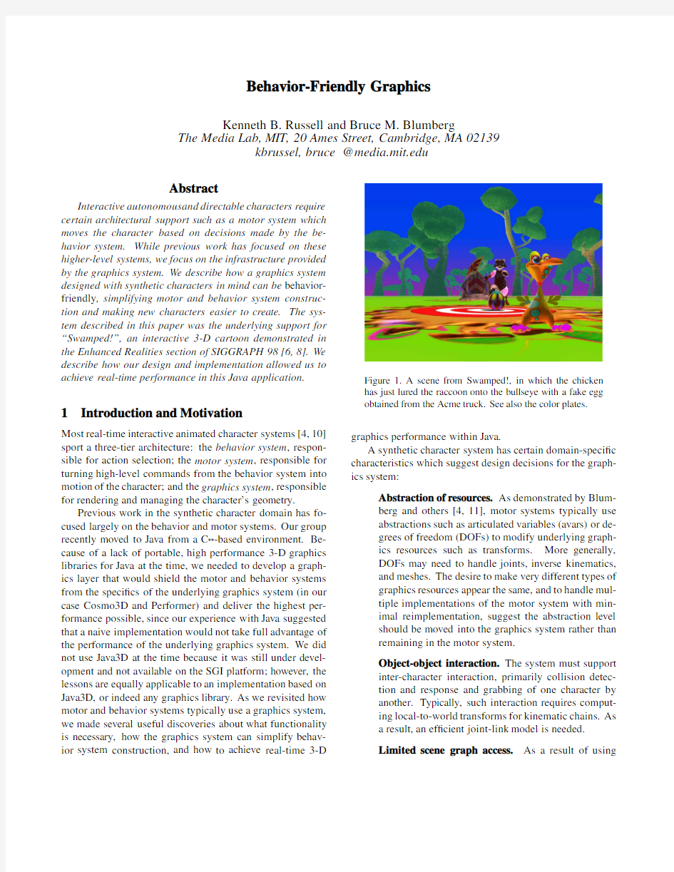
Figure1.A scene from Swamped!,in which the chicken has just lured the raccoon onto the bullseye with a fake egg obtained from the Acme truck.See also the color plates. graphics performance within Java.
A synthetic character system has certain domain-speci?c characteristics which suggest design decisions for the graph-ics system:
Abstraction of resources.As demonstrated by Blum-
berg and others[4,11],motor systems typically use
abstractions such as articulated variables(avars)or de-
grees of freedom(DOFs)to modify underlying graph-
ics resources such as transforms.More generally,
DOFs may need to handle joints,inverse kinematics,
and meshes.The desire to make very different types of
graphics resources appear the same,and to handle mul-
tiple implementations of the motor system with min-
imal reimplementation,suggest the abstraction level
should be moved into the graphics system rather than
remaining in the motor system.
Object-object interaction.The system must support
inter-character interaction,primarily collision detec-
tion and response and grabbing of one character by
another.Typically,such interaction requires comput-
ing local-to-world transforms for kinematic chains.As
a result,an ef?cient joint-link model is needed.
Limited scene graph access.As a result of using
abstractions such as avars or DOFs,only a few hooks
are needed into the underlying scene graph.More
generally,the scene graph is only accessed in certain
well-de?ned and limited ways once it is constructed.
Unidirectional data?ow.A character’s motion comes
either from the character itself(using either procedural
or artist-animated approaches)or from the world(the
application-side object which manages inter-character
interaction such as collision detection).Even in
the case of collisions,characters often respond in
character-speci?c ways.Thus,decisions of how a char-
acter moves are almost always made above the graph-
ics layer.This implies that data?ows unidirectionally
from the application down to the graphics library at run
time.
Cost of communication.Touching the scene graph
is potentially expensive for many reasons:the scene
graph may perform internal updates when writes oc-
cur,the native code interface may be slow,and the
scene graph may be running in another process or on
another machine.The fundamental assumption is that
the underlying scene graph API is native(written in
C++)and/or running in a separate process;either way
there is a cost to crossing that boundary.
Portability and con?gurability.The graphics sys-
tem must target multiple platforms and scene graph
implementations.It should take advantage of multiple
processors or computers if available,and work equally
well if running as a library or in a separate process.
The distinction should be hidden from the motor and
behavior systems.
Speed.The graphics system must be fast.A charac-
ter must not be constrained to six frames per second
(FPS)performance if it requires thirty to express its
personality.
These observations suggest the use of a behavior-friendly graphics layer that sits between the motor system and the na-tive graphics system to implement much of this functionality and to take advantage of characteristics such as unidirectional data?ow to increase performance.
The structure of the rest of the paper is as follows.Sec-tion2discusses related work and the speci?c contributions of this paper.Section3de?nes our terminology and de-scribes avars,DOFs,and the joint-link model.Section4 describes the fundamental functionality the graphics system must provide and how our system implements it.Section5 discusses the issue of state management,which is crucial to high performance.Section6describes our application and its performance.
As a brief introduction to the discussion below,a char-acter’s body in our system is ultimately represented in the underlying graphics library as a scene graph composed of implementation-speci?c nodes such as transforms,shapes, and materials.We use standard modeling packages such as 3D Studio Max2to model our characters and export the ge-ometry as VRML2?les.At load time these?les are read and the underlying scene graph is constructed.In addition,the graphics layer instantiates the objects that the higher layers of the system(e.g.,the motor and behavior systems)will need in order to modify the underlying geometry at run time.The most important of these objects are described below.
2Related Work
Architectures of virtual reality systems are most closely re-lated to this work.The early work of Zeltzer et al.[21] describes the integration into an interactive framework,and application of,modules controlling,for example,user input, inverse kinematics,and dynamics.Appino et al.[1]run such modules on independent computers and use asynchronous communication to avoid round-trip network delays.Shaw et al.[15]decouple the application similarly,and in addition al-low rendering of the scene independently of the computation of the underlying https://www.360docs.net/doc/622504510.html,ter work addresses the issue of reducing lag in such multiprocessor situations.Wloka[20] describes a model for estimating lag and a“just-in-time”syn-chronization approach to minimize it by scheduling processes at the proper times.Jacobs et al.[7]perform just-in-time data acquisition at the appropriate moment in the computa-tion loop to minimize end-to-end lag,and also extrapolate tracking information from their input devices.
The Menv system described by Reeves et al.[11]breaks up a modeling and animation system into a set of tools which run in separate processes and communicate via shared mem-ory.While interactivity is important in this application,this system focuses on enabling the artist to create new animations for characters rather than on generating real-time output.
In the domain of interactive animated characters,Per-lin et al.[10]consider the distribution of characters across both local-and wide-area networks.They run characters’behavior engines on separate computers,rendering from a dedicated machine.Russell et al.[12]applied a similar dis-tributed computation scheme to Blumberg’s behavior system architecture.
The focus of this work differs from the above in several ways.Much of the virtual reality work focuses on the ne-cessity of increasing throughput and decreasing lag for the purpose of making a head-or hand-tracking system more re-sponsive.Our application is much more forgiving of lag,as the user interacts through high-level gestures[8],and we use a projection display for output.Many of the VR applications described in the above papers do not deal with hierarchically
structured objects such as characters with limbs.However, the paradigm we describe of separating the application(such as physical simulation)from the graphics system is present in most of these systems,usually out of necessity;most of these VR systems are implemented in heterogeneous environments of networked single-CPU computers.We go one step further and speci?cally describe how unidirectional data?ow may be attained between our application and graphics subsystem and why this is important for applying parallelism and increasing performance.
Menv addresses many of the same issues as this work (grabbing,for example)and also describes an architecture for implementing an authoring tool for computer animation. This work focuses instead on the graphics support required to implement animated characters with behavior;a tool like Menv might be used to author individual animation segments for characters in a system such as ours.
While earlier work in the interactive character domain has considered the problem of distributing computation and increasing throughput,this work has three speci?c goals not addressed by these earlier works:to describe the graphics-level support needed by a character with behavior,to show how implementing this functionality in the graphics layer rather than the motor or behavior systems simpli?es behavior system construction,and to show how this functionality can be implemented for good performance on both single-and multi-processor systems,providing real-time(30FPS)per-formance in a Java application performing3D graphics in a multi-processor con?guration.
3Avars,DOFs and the Joint-Link Model
We borrow from Reeves et al.[11]the term articulated variable,or avar,to indicate the abstraction of a graphics re-source.Avars can map directly to entities in the scene graph: for example,a Transform node could have rotation,trans-lation,and scale avars created for it,depending on which ?elds of the transform the character’s animations are actually modifying.Avars can also map to more abstract entities like poses of a deforming mesh.Each avar caches the value of its underlying resource to avoid performing a scene graph call when its value is queried.For this reason the uniqueness of avars is critical,and each node in the scene graph is responsi-ble for creating avars for its?elds.A set call on an avar sets only the cache,allowing the motor system to perform multiple sets during its update without sending redundant informa-tion to the graphics system.Get calls return the cached value without accessing the scene graph.A sync method initializes the avar’s value from the scene graph state,and because all motion is generated by the character or the world, needs to be called only at the beginning of time.Changes are sent down via a commit method,which is potentially time consuming and is therefore done only once per frame,at the end of the character’s behavior update.As all run time interaction with the scene graph is mediated through avars, it is crucial for performance reasons that the application not sidestep the avar mechanism(Section5).
A degree of freedom,or DOF,is the motor system’s in-terface to an avar,and adds a locking mechanism necessary for the motor system to arbitrate control of joints among con-?icting motor skills.Our motor system is patterned after that described by Blumberg[4].Since different implementations of the motor system might have different mechanisms for dealing with con?icting motor skills,the locking mechanism was left in the motor system,but the basic abstraction of the graphics resources was moved into the graphics system’s avars.
The joint-link model organizes all of the avars for a charac-ter’s geometric model into a hierarchy,to provide information about its current con?guration.The joint-link model can be queried to obtain a world-to-local or local-to-world transform for any joint in the character.While this information is avail-able in the scene graph’s structure,using the avars’caches avoids scene graph calls when the joint-link model is queried. Using the joint-link model,grabbing functionality can be im-plemented entirely in the application,rather than requiring modi?cations of the scene graph’s structure(Section4.3).
4Core Functionality
4.1Kinematic Animation
A graphics system for synthetic characters must?rst and fore-most support forward kinematic animation.Since most scene graph APIs support hierarchical transforms,the implementa-tion of kinematic animation in the graphics system requires only the creation of avars for joints which were animated by the artist beforehand.We deduce which joints are in use by examining the content of VRML2?les which specify the character’s motion,allowing us to export animations from off-the-shelf packages directly into our system.
An artist-generated animation comes into our system as a series of keyframes specifying the orientation of each joint. As the animation plays,the two keyframes closest to the current time are determined,and an Interpolator object computes the joint’s state,typically using spherical linear interpolation[18].
4.2Mesh Animation
A mesh animation is a set of poses.Each speci?es the vertex positions for a piece of geometry and has an associated alpha value,typically between0.0and1.0.This mechanism can be used to perform facial animation as described by Perlin [10]:for example,“0.7happy,0.3sad”.It can also be used to animate deforming meshes through longer sequences such as a walk cycle;in this case each alpha value corresponds to a keyframe in the animation.
Rather than expose the vertices of the geometrical object to Java,we created a MeshAnim class which allows the Java application to set per-keyframe alpha values.V ertex positions are interpolated in C++code,drastically reducing the amount of data sent from the application to the native graphics library.
A MeshAnim might contain keyframes for several underly-ing pieces of deforming geometry(for example,the body and feet of a chicken;see Section6),and further,contain several animations for all of these geometries(for example, walk,hop,and?y.)Each alpha value corresponds to a pose of all the underlying deforming geometries;note that we re-quire that all animations loaded into a MeshAnim animate the same set of geometries.The alpha values for all of the an-imations are concatenated linearly,so the MeshAnim’s value is an array of?oating point numbers.A MeshAnimAvar provides a cache for this array.
In order to make mesh animations appear the same to the motor system as kinematic animations,we created a MeshAnimInterpolator which keeps track of the range of alpha values in the underlying MeshAnim corresponding to a particular animation.When the interpolator’s value is set to a value between0.0and1.0,it determines the two adjacent keyframes to the current position in the animation and sets their alpha values to blend between the two.We currently interpolate linearly between adjacent keyframes for mesh an-imations,although more sophisticated interpolation schemes could be used to provide better results.
4.3Grabbing
Grabbing conceptually enforces a constraint:one character grabs another,attaching the grabbed character to the grabber’s end effector.In our system,grabbing is implemented using the joint-link model(Section3),which provides the local-to-world transform for the end effector.This is then composed with the grabbed character’s current desired orientation and an optional offset transform to determine its new position each frame.
A similar result could be obtained by reparenting the ge-ometry of the grabbed character in the scene graph,which would require less per-frame computation.This approach would,however,expose the scene graph structure to the Java application,reducing portability.In addition,it would re-quire that the geometric structure of the character correspond directly to the hierarchy in the scene graph.This correspon-dence does not hold for characters animated entirely with MeshAnim s,because one piece of geometry(the“skin”) corresponds to several pieces of rigid geometry connected by transforms in a kinematically animated character.We allow MeshAnim-animated characters to grab others by animating a set of transforms corresponding to the character’s hierarchy simultaneously with the deforming mesh.These transforms contain no geometry,however.
ALIVE[3]implemented grabbing as a motor skill.Push-ing this functionality down into the graphics system makes creation of new characters simpler because the default grab-bing behavior“does the right thing”with no additional imple-mentation work.Both grabber and grabbee are noti?ed that a grab has begun or ended and can make behavior-level deci-sions on this information,so customization,such as playing
a squirm animation upon being grabbed,is also possible.
4.4Collision Detection and Response
Rather than perform full polygon-polygon collision detection, we chose to use simpli?ed bounding volumes.Our system currently supports spheres and oriented bounding boxes that can either be speci?ed by the artist or computed automat-ically by the graphics system.The bounding volumes are updated by the application rather than the native graphics layer to maintain unidirectional data?ow.Collision response can be turned on and off on a per-character basis,and we support VRML-style“proximity sensors”which are collid-able objects that do not induce a collision response in the character.
When a collision is detected between two characters,the behavior system of each collided character is noti?ed.Char-acters can thereby react to collisions in more sophisticated ways than following the simple“no interpenetration”rule enforced by the graphics system.For example,the houses in our system wiggle when they are collided against to indicate that they are live characters with which one can interact.
Support for collision detection in the graphics system, combined with a link to the behavior system,vastly sim-pli?es behavior system construction.ALIVE,for example, required behaviors to be added to each character for proximity detection and collision response.
5Achieving High Performance
5.1Smart State Management
As mentioned in Section1,we make the fundamental assump-tion that accessing the scene graph is an expensive operation, for writes as well as for reads.The application therefore needs to be clever about where it stores its state to minimize calls down into the native graphics layer.
The avar mechanism provides caches for all values being read or written in the scene graph below,with the following two results:?rst,redundant writes to a particular avar do not cause redundant communication with the native graph-ics layer,since avars are written once per frame when their commit method is called.Second,and more importantly,all “get”calls to the scene graph are avoided at run time.Gets are especially expensive because they require the application and native graphics layer to synchronize.When the native graphics layer is embedded in the same process as the appli-cation,as when it is used as a library,this synchronization is
Figure2.System architecture,indicating links across which
parallel processing can occur.
irrelevant.However,when the native graphics layer is run in parallel,as on a multiprocessor or multi-computer con?gura-tion,synchronization is disastrous to performance.To make the caches work properly,it is crucial that the application not sidestep the avar mechanism and deal with the scene graph directly.
5.2Parallelism Support
On a uniprocessor machine a serial implementation of the native graphics layer is most ef?cient.However,running the native graphics layer in parallel to the application can provide a signi?cant speed improvement when another processor or computer is available.Unidirectional data?ow at run time is the primary property of the system which makes it amenable to parallelization.This property came about because of the nature of the graphics system’s design;for example,complex scene graph reorganization and geometry creation at run time were prohibited.While it may seem that the constraints imposed by this design were too restrictive,in practice we found that the system handled all of the operations we needed to build our characters,and the speed improvements afforded by a parallel implementation more than made up for the initial adjustment to our interface design from that of a more general scene graph API.
Our parallelization approach partitions the program into two distinct pieces:the application(written in Java),and the graphics(written in C++).The strong distinction between the two is indicated in Figure2.The application and graphics class BiDirPipe
public:
virtual bool read(void*dest,int size)=0;
virtual bool write(void*dest,int size)=0;
virtual bool poll()=0;
virtual void flush()=0;
virtual void lock()=0;
virtual void unlock()=0;
;
Figure3.BiDirPipe base class.programs run either in separate processes on the same com-puter or on two different computers connected by a network. In both con?gurations all of the communication between Java and the graphics program occurs via a small native class called a BiDirPipe(Figure3),which is implemented either with shared memory[17]or a socket[16].
The simple protocol used to communicate between the Java application and the graphics process is similar to that in a Remote Procedure Call[16]mechanism;see Appendix A for details.All graphics API methods returning void,most signi?cantly rendering,are done in parallel to the main ap-plication.The structure is essentially a software pipeline for the graphics system on top of that already implemented by the scene graph API.
An early comparison between serial and parallel bindings of Cosmo3D on a multiprocessor SGI Onyx2showed an increase from19.2FPS for the serial implementation to31.25 FPS for the parallel,a50%speed improvement.Note that this did not require any changes to the underlying graphics library,but merely changed the interface to it.
6Results
We developed an interactive3D cartoon,“Swamped!”[6,8], in which the protagonist,K.F.Chicken,thwarts the raccoon’s attempts to steal his eggs;see Figure1and the color plates. Swamped!was demonstrated as part of SIGGRAPH98’s Enhanced Realities exhibition.The chicken is a directable character,controlled by the user via a plush toy instrumented with sensors,while the raccoon is fully autonomous.The raccoon is a standard hierarchical model with43rotational joints and a face morphed among six primary facial expres-sions using mesh animation;the model contains8000tri-angles.The chicken is a combined hierarchical model and deformable mesh;its body and feet are animated solely with mesh animation,while its head and wings are rigid pieces of geometry which have squash and stretch added with non-uniform scales.The chicken has over600keyframes for all of its body animations(for example,walk,jump,and run),and contains3500triangles.Three houses animated with mesh animation total roughly6000triangles.
Swamped!has been run on a two-processor400MHz Pentium II PC using Cosmo3D,on an8-processor Silicon Graphics Onyx2using Performer,and in a hybrid mode in which the Java application runs on a PC,communicating over 100Mbps Ethernet to the Performer-based graphics system running on the Onyx2.Because the Java just-in-time com-piler is highly optimized on the PC,the latter is the fastest con?guration:the per-frame behavior and motor system up-dates take roughly20ms,while the writing of the current frame’s graphics commands to a socket takes10ms.We achieve sustained30FPS performance because all render-ing is done in parallel,no round-trip queries are made to the
graphics system by the Java application at run time,and the underlying graphics library is fast enough to keep up with the Java application.The limiting factor is the communication overhead.
7Conclusion
We have presented a graphics system which is“behavior-friendly”,designed with synthetic characters in mind.We have described the criteria which the graphics system must meet,the structure which the synthetic character domain sug-gests,and the advantages,such as unidirectional data?ow, that structure provides.We have discussed kinematic and mesh animation,grabbing,and collision detection and re-sponse in the context of our graphics system,and have shown how moving higher-level concepts into the graphics layer simpli?es behavior system construction,making new char-acters easier to design.Finally,we have shown that using a parallel approach it is indeed possible to achieve real-time 3-D graphics performance in a non-trivial Java application. 8Acknowledgments
We thank the rest of the Swamped!team:Michal Hlavac (who also drew Figure2),Christopher Kline,Michael P. Johnson,Teresa Marrin,Bill Tomlinson,Andrew Wilson, Song-Yee Y oon,and Marc Downie;our UROPs who helped on this project as well as Swamped!:Jeremy Lueck,Dan Stiehl,Zoe Teegarden,and Jed Wahl;and Dr.Joseph Paradiso for the chicken’s sensor systems.
References
[1]P.A.Appino,J.B.Lewis,L.Koved,D.T.Ling,D.A.
Rabenhorst,and C.F.Codella.An architecture for virtual worlds.Presence,1(1):1–17,1992.
[2]David Beazley.Simpli?ed wrapper and interface gen-
erator.1995.https://www.360docs.net/doc/622504510.html,/.
[3]Bruce Blumberg.Old Tricks,New Dogs:Ethology
and Interactive Creatures.PhD thesis,Massachsetts Institute of Technology,1996.
[4]Bruce Blumberg and Tinsley Galeyan.Multi-level di-
rection of autonomous characters for real-time virtual environments.In Computer Graphics Proceedings, SIGGRAPH95,pages47–54.ACM,1995.
[5]J¨u rgen D¨o llner and Klaus Hinrichs et al.Modeling
and animation machine/virtual rendering system.1998.
http://wwwmath.uni-muenster.de/?mam/.
[6]Bruce M.Blumberg et al.Swamped!:Using plush
toys to direct autonomous animated characters.In SIGGRAPH98Conference Abstracts and Applications.
ACM,1998.
[7]M.Jacobs,M.Livingston,and A.State.Managing
latency in complex augmented reality systems.In Pro-ceedings,Symposium on Interactive3D Graphics,1997.
[8]M.P.Johnson,A.Wilson,B.Blumberg,C.Kline,and
A.Bobick.Sympathetic interfaces:Using a plush toy to
direct synthetic characters.In CHI99,1999.To appear.
[9]Sheng Liang.Java Native Interface:Program-
ming Guide and Reference.Addison-Wesley,1998.
https://www.360docs.net/doc/622504510.html,/products/jdk/
1.1/docs/guide/jni/.
[10]Ken Perlin and Athomas Goldberg.Improv:A sys-
tem for scripting interactive actors in virtual worlds.
In Computer Graphics Proceedings,SIGGRAPH96, pages205–16.ACM,1996.
[11]William T.Reeves,Eben F.Ostby,and Samuel J.Lef?er.
The Menv modelling and animation environment.Jour-nal of Visualization and Computer Animation,1(1):33–40,August1990.
[12]K.Russell,B.Blumberg,A.Pentland,and P.Maes.
Distributed alive.In SIGGRAPH96Technical Sketches.
ACM,1996.
[13]Kenneth B.Russell.An automatic C++to Scheme in-
terface generator.1995.
https://www.360docs.net/doc/622504510.html,/?kbrussel/
Header2Scheme/.
[14]Kenneth B.Russell.A Scheme binding for Open Inven-
tor.1995.https://www.360docs.net/doc/622504510.html,/
?kbrussel/Ivy/.
[15]C.Shaw,M.Green,J.Liang,and Y.Sun.Decoupled
simulation in virtual reality with the mr toolkit.ACM Transactions on Information Systems,11(3):287–317, July1993.
[16]W.Richard Stevens.UNIX Network Programming,
chapter4.Prentice Hall,1990.
[17]W.Richard Stevens.Advanced Programming in the
UNIX Environment,chapter14.Addison-Wesley,1992.
[18]Alan Watt and Mark Watt.Advanced Animation and
Rendering Techniques,chapter15.Addison-Wesley, 1992.
[19]Jeff White.A Java binding for Open Inventor.1996.
http://www.igd.fhg.de/CP/kahlua/. [20]Matthias https://www.360docs.net/doc/622504510.html,g in multiprocessor virtual reality.
Presence,4(1):50–63,1995.
void Java graphics Transform setTranslation( jobject javaTransform,
jfloat x,jfloat y,jfloat z)
Transform*xform=
ExtractCPlusPlusTransformFromJavaTransform(
javaTransform);
xform->setTranslation(x,y,z);
Figure 4.Serial mechanism for glue code,illustrating
the mapping of the setTranslation method of a
Transform class from Java to C++.
[21]D.Zeltzer,S.Pieper,and D.Sturman.An integrated
graphical simulation platform.In Graphics Interface ’89,pages266–74,Toronto,Canada,1989.Canadian Inf.Process Soc.
A Interface Speci?cs
There are two ways to bind a native C++library into an in-terpreted language:a standard,serial method,and our new, parallel method.This section compares the two and describes the speci?cs of our parallel interface.We restrict our example to Java and the Java Native Interface[9]for calling C++code from Java,although our method could be applied to any lan-guage with a foreign function interface.
Methods in a Java class can be speci?ed as“native”, meaning the interpreter will call a C function rather than a Java method.A C++library can be bound into Java by creating a Java-side wrapper class for each C++class,which contains native methods analogous to those in the C++class.Each of these native methods turns around and calls the method on the underlying C++object.Figure4illustrates the standard mechanism for this Java to C++mapping,which we use for our uniprocessor graphics library binding.There are tools avail-able to generate such glue code automatically[13,2],and all currently available3D API bindings for interpreted lan-guages(for example,Ivy[14],Kahlua[19],and MAM/VRS [5])follow this pattern.
To allow parallel processing of graphics calls,we ex-plicitly split the C++graphics layer into its own process, and manage communication with the Java process with a BiDirPipe(Figure3).All Java calls to set methods on graphics objects correspond to a write on this pipe.All calls to get methods must write the request to the pipe,?ush it,and wait for the graphics process to respond.Asyn-chronous writes from the graphics process back to Java are not allowed in our protocol.Figure5illustrates the Java side of this communications mechanism.In the graphics pro-cess,a dispatcher reads the message ID and calls a function which reads the rest of the message and calls the appropriate method(setTranslation)on the C++object.For clarity, byte swapping macros are not included in this example,but are required when passing elementary types such as ints and
typedef enum
TRANSFORM SET TRANSLATION,
...
GraphicsMessageId;
typedef struct
//For example,‘‘TRANSFORM SET TRANSLATION’’
int messageId;
//For the C++object
void*nativePtr;
//New values for
//the transform’s translation
float x,y,z;
MessageV3f;
void Java graphics Transform setTranslation( jobject javaTransform,
jfloat x,jfloat y,jfloat z)
BiDirPipe*pipe=
ExtractBiDirPipeFromJavaGraphicsObject(
javaTransform);
MessageV3f message;
message.messageId=
(int)TRANSFORM SET TRANSLATION;
message.nativePtr=
ExtractCPlusPlusTransformFromJavaTransform(
javaTransform);
message.x=x;
message.y=x;
message.z=x;
pipe->lock();
pipe->write(&message,sizeof(message));
pipe->unlock();
Figure5.A complete example of the Java side of our parallel
processing glue code mechanism.All of the C++code in the
setTranslation method is executed in another process, in parallel to the Java code which called this native method.
?oats between little-endian and big-endian architectures;see Stevens[16]for details.Our convention,as in many RPC implementations,is to send only big-endian data over the pipe.
This parallel glue code structure requires a signi?cant amount of additional mechanism over the standard serial structure.In addition,it is best suited for applications which are cleanly divisible into modules which have unidirectional data?ow,and must be accompanied by Java-side caches to avoid round trip calls to the remote process.Despite the extra effort required to implement it,this new glue code structure provides signi?cant advantages over the serial version.The ability to distribute the computation and the associated per-formance increase is primary among these.Debugging of the graphics process is made easier,since it is not embedded in the Java process.In addition,graphics calls may be made in multiple Java threads regardless of whether the underlying C++graphics library is thread-safe,since communication is mediated and serialized by the BiDirPipe.
电路图参数
机子我早已上传好多次了,是放电老师的双混后级,主变EE42 1。30*4 。。。。3+3 次级0。64 。。。90 10 0。9 的线 4T 《为给后级的驱动板稳压供电》后级高压电容82U 500V,硅用1225 电感用EE42用1。2绕上95T,是刚好绕满,关断电容用5U风扇电容 以前做这个电路有直通现象,现已找到解决的办法了。主要是后级的电源不再从电池那里取了。而是从主变压器那里取16V下来然后稳压处理等。再经过个继电器,《目的是想让高压电容先充好电。》这个思路很成功,多谢兄弟们的指点。 放电机器: 按电路图更改: RW2不要,R*不要,R18不要,RW3不要,R20=0欧(短路它),R19=22K,C17=5UF,R25=100K,做成不要调节,就可以电罗非了,关断电感可调整一下。 但现在夏天罗非的活动能力增大,是会难电一点。 1/直通:主电高压经水阻向关断电容充电(电容越大越没法充满),这是主要因素,有二种原因,一前级功率不足,二水阻太高,如前级功率不足会造成主电压下跌,电容充电时间延长,此时硅已导通,电容的能量没法和关断电感组成LC振荡周期产生最大能量的反电压旁路于硅的A/K二端。如水阻太高,串联水阻的电流对电容充电没法达到关断能量,硅导通电流大于LC旁路所产生的反压的导通电流,这些情况只给提高主高压或减小关断电容的容量,增加电感量来减少损耗,提升关断能量。 2/功率:EE42配二对170N06有足够的指标达到600W,但变压器用1*4(0.7*4=2.8*7=20A),只有400W左右的功率,后级配用5UF电容明显不匹配,想法把初级线截面积增大到5平方才能有效,还有前级驱动的死区不宜过大,会造成尖峰电压干扰其它电路.(死区电阻是限制最大占空比(5/7脚之间的电阻),因为已经限制了就叫死区,但1-2脚之间的电压比较或改变9脚电压都可以在最大占空比之内改变,8脚可以改变启动时区内改变占空比,是在特别电路中采用。在推挽电路中常规是47%左右,但下降到43%以下,因变压器的漏感在死区的时间内产生储能磁场无法(适)放,而产生反向电动势(尖峰电压)与下一个反向半波叠加经变压器能量转移造成损耗。还有一路损耗在于振铃造成开关管的直接损耗,但占空比无级变化可改变输出有效值电压的变化(输出稳压的应用),但应用时在输出串入电感隔离尖峰的小脉冲。)制作中注意事项,频率高只能用小关断电容,水阻低就要增大关断电容,频率低要增大电感,功率小要增大电感,减小电容,功率大可增大电感,增大电容,等等。。。硅电路最好用灯泡试机,用二只或三只200W串联,因为冷阻时能关断热阻时也能关断才算合格,走不到二个极端不算合格。 大海一号: 以前有的那些问题,还没有出现,控罗非,还是很不错的,使用倍为720V,电感用205T 25*25,电容5U,那条里鱼从草里窜出来,罗非转几下就能定鱼了,从电的效果来说跟1500W有可圈可点。注。原图的R*改为10K。加大前级后,从电感那听到的声音会比以前的强劲,200W,电池够时,720V倍压档可以点闪爆它。下水4平方还是比较热的。
实验一逻辑门电路的基本参数及逻辑功能测试
实验一逻辑门电路的基本参数及逻辑功能测试 一、实验目的 1、了解TTL与非门各参数的意义。 2、掌握TTL与非门的主要参数的测试方法。 3、掌握基本逻辑门的功能及验证方法。 4、学习TTL基本门电路的实际应用。 5、了解CMOS基本门电路的功能。 6、掌握逻辑门多余输入端的处理方法。 二、实验仪器 三、实验原理 (一) 逻辑门电路的基本参数 用万用表鉴别门电路质量的方法:利用门的逻辑功能判断,根据有关资料掌握电路组件管脚排列,尤其是电源的两个脚。按资料规定的电源电压值接 好(5V±10%)。在对TTL与非门判断时,输入端全悬空,即全 “1”,则输出端用万用表测应为以下,即逻辑“0”。若将其 中一输入端接地,输出端应在左右(逻辑“1”),此门为合格 门。按国家标准的数据手册所示电参数进行测试:现以手册中 74LS20二-4输入与非门电参数规范为例,说明参数规范值和测试条件。 TTL与非门的主要参数 空载导通电源电流I CCL (或对应的空载导通功耗P ON )与非门处于不同的工作状态,电 源提供的电流是不同的。I CCL 是指输入端全部悬空(相当于输入全1),与非门处于导通状态,
输出端空载时,电源提供的电流。将空载导通电源电流I CCL 乘以电源电压就得到空载导通功 耗P ON ,即 P ON = I CCL ×V CC 。 测试条件:输入端悬空,输出空载,V CC =5V。 通常对典型与非门要求P ON <50mW,其典型值为三十几毫瓦。 2、空载截止电源电流I CCh (或对应的空载截止功耗P OFF ) I CCh 是指输入端接低电平,输出端开路时电源提供的电流。空载截止功耗POFF为空载 截止电源电流I CCH 与电源电压之积,即 P OFF = I CCh ×V CC 。注意该片的另外一个门的输入也要 接地。 测试条件: V CC =5V,V in =0,空载。 对典型与非门要求P OFF <25mW。 通常人们希望器件的功耗越小越好,速度越快越好,但往往速度高的门电路功耗也较大。 3、输出高电平V OH 输出高电平是指与非门有一个以上输入端接地或接低电平的输出电平。空载时,输出 高电平必须大于标准高电压(V SH =);接有拉电流负载时,输出高电平将下降。 4、输出低电平V OL 输出低电平是指与非门所有输入端接高电平时的输出电平。空载时,输出低电平必须低于标准低电压(VSL=);接有灌电流负载时,输出低电平将上升。 5、低电平输入电流I IS (I IL ) I IS 是指输入端接地输出端空载时,由被测输入端流出的电流值,又称低电平输入短路 电流,它是与非门的一个重要参数,因为入端电流就是前级门电路的负载电流,其大小直 接影响前级电路带动的负载个数,因此,希望I IS 小些。
carsim软件介绍
carsim软件介绍 CarSim是专门针对车辆动力学的仿真软件,CarSim模型在计算机上运行的速度比实时快3-6倍,可以仿真车辆对驾驶员,路面及空气动力学输入的响应,主要用来预测和仿真汽车整车的操纵稳定性、制动性、平顺性、动力性和经济性,同时被广泛地应用于现代汽车控制系统的开发。CarSim可以方便灵活的定义试验环境和试验过程,详细的定义整车各系统的特性参数和特性檔。CarSim软件的主要功能如下: n 适用于以下车型的建模仿真:轿车、轻型货车、轻型多用途运输车及SUV; n 可分析车辆的动力性、燃油经济性、操纵稳定性、制动性及平顺性; n 可以通过软件如MATLAB,Excel等进行绘图和分析; n 可以图形曲线及三维动画形式观察仿真的结果; n 包括图形化数据管理接口,车辆模型求解器,绘图工具,三维动画回放工具,功率谱分析模块; n 程序稳定可靠; n 软件可以实时的速度运行,支持硬件在环,C arSim软件可以扩展为CarSim RT, CarSim R T 是实时车辆模型,提供与一些硬件实时系统的接口,可联合进行HIL仿真; n 先进的事件处理技术,实现复杂工况的仿真; n 友好的图形用户接口,可快速方便实现建模仿真; n 提供多种车型的建模数据库; n 可实现用户自定义变量的仿真结果输出; n 可实现与simulink的相互调用; n 多种仿真工况的批运行功能; CarSim特点 1、使用方便 软件的所有组成部分都由一个图形用户接口来控制。用户通过点击“Run Math Model”来进行仿真。通过点击“Animate”按钮可以
以三维动画形式观察仿真的结果。点击“Plot”按钮可以察看仿真结果曲线。很短的时间内,你就可以掌握C arSim的基本使用方法,完成一次简单仿真并观察仿真结果。 所要设置或调整的特性参数都可以在图形接口上完成。150多个图形窗口使用户能够访问车辆的所有属性,控制输入,路面的几何形状,绘图及仿真设置。利用CarSim的数据库建立一个车辆模型并设置仿真工况,在很短的时间内即可完成。在数据库里有一系列的样例并允许用户建立各种组件、车辆及测试结果的库檔。这一功能使得用户能够迅速地在所做的不同仿真之间切换,对比仿真结果并作相应的修改。 车辆及其参数是利用各种测试手段所得到的数据和表格,包括实验测试及悬架设计软件的仿真测试等。CarSim为快速建立车辆模型提供了新的标准。 2、报告与演示 CarSim输出的资料可以导出并添加到报告、excel工作表格及Pow erPoint演示中。仿真的结果也可以很方便地导入到各种演示软件中。 3、快速 CarSim将整车数学模型与计算速度很好地结合在一起,车辆模型在主频为3GHz的PC机上能以十倍于实时的速度运行。速度使得CarSim很容易支持硬件在环(HIL)或软件在环(SIL)所进行的实时仿真。CarSim支持Applied Dynamics Internatinal(A DI), A&D, dSPACE,ETAS,Opal-R T及其它实时仿真系统。CarSim这一快速特性也使得它可以应用于优化及试验设计等。 4、精度及验证 CarSim建立在对车辆特性几十年的研究基础之上,通过数学模型来表现车辆的特性。每当加入新的内容时,都有相应的实验来验证。使用CarSim的汽车制造商及供货商提供了很多关于实验结果与CarSim仿真结果一致性的报告。 5、标准化及可扩展性 CarSim可以在一般的Windows系统及便携式计算机上运行。CarSim也可以在用于实时系统的计算机上运行。数学模型的运动关系式已经标准化并能和用户扩展的控制器,测试设备,及子系统协调工作。这些模型有以下三种形式: n Carsim函数自带的内嵌模块。 n 嵌入模型的MATLAB/Simulink S-函数 n 具有为生成单独EXE檔的可扩展C代码的库檔 6、有效、稳定、可靠 CarSim包括了车辆动力学仿真及观察结果所需的所有工具。MSC利用先进的代码自动生成器来生成稳定可靠的仿真程序,这比传统的手工编码方式进行软件开发要快很多。 需要进一步了解的朋友们可以加我QQ哦12603839
影响运放电路的误差的几个主要参数
影响运放电路的误差的几个主要参数(KCMR,VIO,Iib,Iio等) 1.共模抑制比KCMR为有限值的情况 集成运放的共模抑制比为有限值时,以下图为例讨论。 VP=Vi VN=Vo 共模输入电压为: 差摸输入电压为: 运算放大器的总输出电压为:vo=A VD v ID+A VC v IC
闭环电压增益为: 可以看出,Avd和Kcmr越大,Avf越接近理想情况下的值,误差越小。 2.输入失调电压V IO 一个理想的运放,当输入电压为0时,输出电压也应为0。但实际上它的差分输入级很难做到完全对称。通常在输入电压为0时,存在一定的输出电压。 解释一:在室温25℃及标准电源电压下,输入电压为0时,为使输出电压为0,在输入端加的补偿电压叫做失调电压。 解释二:输入电压为0时,输出电压Vo折合到输入端的电压的负值,即V IO=- V O|VI=0/A VO 输入失调电压反映了电路的对称程度,其值一般为±1~10mV
3.输入偏置电流I IB BJT集成运放的两个输入端是差分对管的基极,因此两个输入端总需要一定的输入电流I BN和I BP。输入偏置电流是指集成运放输出电压为0时,两个输入端静态电流的平均值。 输入偏置电流的大小,在电路外接电阻确定之后,主要取决于运放差分输入级BJT的性能,当它的β值太小时,将引起偏置电流增加。偏置电流越小,由于信号源内阻变化引起的输出电压变化也越小。其值一般为10nA~1uA。 4.输入失调电流I IO 在BJT集成电路运放中,当输出电压为0时,流入放大器两输入端的静态基极电流之差,即I IO=|I BP-I BN| 由于信号源内阻的存在,I IO会引起一个输入电压,破坏放大器的平衡,使放大器输出电压不为0。它反映了输入级差分对管的不对称度,一般约为1nA~0.1uA。 5.输入失调电压VIO、输入失调电流IIO不为0时,运算电路的输出端将产生误差电压。 设实际的等效电路如下图大三角符号,小三角符号内为理想运放,根据VIO和IIO的定义画出。
电源基础知识(电源的基本参数)
四、电源的基本参数 1电压 2输入电压 就是市电电压。 国内电压是220V,但电网电压并不是时刻稳定在220V,而是有一定的波动。采用被动PFC 的电源,可以适应的电网电压一般是在180~264V 之间,当电压突然降低到180V 以下时,电源会出现重新启动的现象;电压偏高,则会导致电源保险烧毁。 第15 页 部分电源可以承受电压的缓慢下降,甚至电压缓降到180V 以下时,也可以正常工作, 但此时电源的负载能力也将下降,难以达到额定功率的输出。采用了主动PFC 电路的电源,适应电压可以扩大到90~264V,在此区间均可正常使用。需要指出的是,不是所有 主动PFC 电源,都是宽电压设计。 4.1.2 输出电压 就是电源输出给电脑使用的直流电压。 ATX 电源输出的直流电压有+5V、+12V、-12V 、+5VSB、+3.3V。 同样,电源所输出的直流电压也会有一定的波动。我们允许输出电压有一定的波动,但不能超过INTEL 所界定的范围,正电压允许在基准值上下5%之内波动,而负电压允许在上下10%之内波动,如+5V 的正常范围是4.75~5.25V,而-12V 的正常范围是-10.8~-13.2V 。 要求电源在空载、轻载、典型负载与满载状态下,各路输出电压均在允 许范围 内。当超过此范围,电脑运行就有可能出现问题。检测电源的输出电压需要使用万用表等设备,软件检测的结果往往并不精确。电源输出电压的稳 定性,是电源的一个重要指标,但绝不是判断一款电源优劣的唯一指标。电源性能指标非常繁多,电压的稳定性只是其中一项。只要电源输出在合理的范围内,对电脑配件都不会造成负面影响,这时电压的波动范围在1%和5%的意义是一样的,过分地关注波动的大小是不必要的。但波动的相对大小,侧面反映了电源的负载能力,波动率相对越小的电源,其实际的最大输出功率可能越大,毕竟,输出电压超出规定范围时的输出功率是没有益处的。 相对来说,电压偏高比电压偏低更具有危险性,电压偏低至多引起电脑工作的不正常,而电压偏高则可能烧毁硬件。一
Carsim整车建模的参数
车体空载情况下的车体信息 (1 )簧上质量的质心距前轴的距离mm (2 )簧上质量质心距地面的高度mm (3 ) 轴距mm (4 ) 质心的横向偏移量mm (5 )簧载质量kg (6 )对x 轴的极惯性矩( lxx ) kg-m2 (7)对y 轴的极惯性矩( lyy ) kg-m2 (8 )对z 轴的极惯性矩( lzz ) kg-m2 (9) 对x、y 轴的惯性积( lxy )kg-m2 (10) 对x、z 轴的惯性积( lxz )kg-m2 (11) 对y、z 轴的惯性积( lyz )kg-m2 二空气动力学 (1) 空气动力学参考点X mm (2) 空气动力学参考点Y mm (3) 空气动力学参考点Z mm (4 ) 迎风面积m2 (5 )空气动力学参考长度mm (6 )空气密度kg/m3
(7 )CFx(空气动力学系数)与slip angle ( 行车速度方向与空气流动 方向的夹角) 的关系 (8) CFy 与slip angle的关系 (9) CFz 与slip angle的关系 (10) CMx与slip angle 的关系 (11) CMy与slip angle 的关系 (12) CMz与slip angle 的关系 三传动系 1 最简单的一种 (1) 后轮驱动所占的比值,为1时,后轮驱动;为0 时,前轮驱动 (2 )发动机的功率KW 2 前轮驱动或后轮驱动 1)发动机特性 (1 )各个节气门位置下,发动机扭矩(N-m)与发动机转速 (rpm) 的 关系 (2 )打开节气门的时间迟滞sec
(3 ) 关闭节气门的时间迟滞sec (4 ) 曲轴的旋转惯量kg-m2 (5 ) 怠速时发动机的转速rpm 2)离合器特性 a 液力变矩器 (1) 扭矩比(输出比输入)与速度比(输出比输入)的关系 (2) 液力变矩器的参 数1/K 与速度比(输出比输入)的关系 (3) 输入轴的转动惯 量kg-m2 (4) 输出轴的转动惯 量kg-m2 b 机械式离合器 (1 )输出的最大扭矩(N-m)与离合器接合程度 (0代表完全结合, 1 代表完全分离)的关系 (2 )接合时间迟滞sec (3 )分离时间迟滞sec (4 )输入轴的转动惯量kg-m2 (5 )输出轴的转动惯量kg-m2 3)变速器(1 )正向挡位和倒挡的传动比,转动惯量(kg-m2),正向传动与反向
Carsim整车建模参数
Carsim整车建模参数 一车体 空载情况下的车体信息 (1) 簧上质量的质心距前轴的距离mm (2) 簧上质量质心距地面的高度mm (3) 轴距mm (4) 质心的横向偏移量mm (5) 簧载质量kg (6) 对x轴的极惯性矩(lxx)kg-m2 (7) 对y轴的极惯性矩(lyy)kg-m2 (8) 对z轴的极惯性矩(lzz)kg-m2 (9) 对x、y轴的惯性积(lxy)kg-m2 (10) 对x、z轴的惯性积(lxz)kg-m2 (11) 对y、z轴的惯性积(lyz)kg-m2 二空气动力学 (1) 空气动力学参考点X mm (2) 空气动力学参考点Y mm (3) 空气动力学参考点Z mm (4) 迎风面积 m2 1 (5) 空气动力学参考长度 mm (6) 空气密度 kg/m3 (7) CFx(空气动力学系数)与slip angle (行车速度方向与空气流 动方向的夹角)的关系 (8) CFy与slip angle的关系 (9) CFz与slip angle的关系 (10) CMx与slip angle的关系
(11) CMy与slip angle的关系 (12) CMz与slip angle的关系 三传动系 1 最简单的一种 (1) 后轮驱动所占的比值,为1时,后轮驱动;为0时,前轮驱动 (2) 发动机的功率KW 2 前轮驱动或后轮驱动 1)发动机特性 (1) 各个节气门位置下,发动机扭矩(N-m)与发动机转速(rpm) 的 2 关系 (2) 打开节气门的时间迟滞sec (3) 关闭节气门的时间迟滞sec (4) 曲轴的旋转惯量kg-m2 (5) 怠速时发动机的转速rpm 2)离合器特性 a 液力变矩器 (1) 扭矩比(输出比输入)与速度比(输出比输入)的关系 (2) 液力变矩器的参数1/K与速度比(输出比输入)的关系 (3) 输入轴的转动惯量kg-m2 (4) 输出轴的转动惯量kg-m2 b 机械式离合器 (1) 输出的最大扭矩(N-m)与离合器接合程度(0代表完全结合, 1代表完全分离)的关系 (2) 接合时间迟滞sec
常用集成电路及主要参数
1 附录四、常用集成电路及主要参数 4.1 常用集成电路的引线端子识别及使用注意事项 4.1.1 集成电路引出端的识别 使用集成电路前,必须认真查对和识别集成电路的引线端,确认电源、地、输入、输出及控制端的引线号,以免因错接损坏元器件。 贴片封装(A、B)型,如附图4.1-1所示,识别时,将文字符 号正放,定位销向左,然后,从左下角起,按逆时针方向依次 为1、2、3……。 扁形和双列直插型集成电路:如附图 4.1-2(b)所示,识别 时,将文字符号标记正放,由顶部俯视,其面上有一个缺口或 小圆点,附图4.1-1贴片型,有时两者都有,这是“1”号引线 端的标记,如将该标记置于左边,然后,从左下角起,按逆时 针方向依次为1、2、3……。 一般圆型和集成电路:如附图4.1-2(a)所示,识别时,面向引出端,从定位销顺时针依次为1、2、3……。圆形多用于模拟集成电路。 (a) 园形外型(b)扁平双列直插型 附图4.1-2 集成电路外引线的识别 4.1.2 数字集成电路的使用 数字集成电路按内部组成的元器件的不同又分为:TTL电路和CMOS电路。不论哪一种集成电路,使用时,首先应查阅手册,识别集成电路的外引线端排列图,然后按照功能表使用芯片,尤其是牛规模的集成电路,应注意使能端的使用,时序电路还应注意“同步”和“异步”功能等。 使用集成路时应注意以下方面的问题。 1、TTL电路 (1)电源 ①只允许工作在5V±10%的范围内。若电源电压超过5.5V或低于4.5V,将使器件损坏或导致器件工作的逻辑功能不正常。 ②为防止动态尖峰电流造成的干扰,常在电源和地之间接人滤波电容。消除高频干扰的滤波电容取0.01~0.1PF,消除低频干扰取10—50/uF ③不要将“电源”和“地”颠倒,例如将741S00插反,缺口或小圆点置于右面,则电源的引线端与“地”引线端恰好颠倒,若不注意,这种情况极易发生,将造成元器件的损坏。 ④TTL电路的工作电流较大,例如中规模集成TTL电路需要几十毫安的工作电流,因此使用干电池长期工作,既不经济,也不可靠。 (2)输出端 ①不允许直接接地或接电源,否则将使器件损坏。 ②图腾柱输出的TTL门电路的输出端不能“线与”使用,OC门的输出端可以
CarSim_Simulink
Simulink接口 (1)变量由Simulink导入CarSim(导入变量) 可由Simulink导入到CarSim中的变量可达160多个,主要分为以下 几部分: 控制输入 轮胎/路面输入 轮胎的力和力矩 弹簧及阻尼力 转向系统的角度 传动系的力矩 制动力矩及制动压力 风的输入 任意的力和力矩 我们可以在Simulink中定义变量,也可以在其他软件中定义并导入Simulink模型中,导入的变量将叠加到CarSim内部相应的变量中。
Simulink接口 2)变量由CarSim导入Simulink(导出变量) 导出变量可以应用于用户自定义的Simulink模型,CarSim的导 出变量多达560之多,如车辆的位置、姿态、运动变量等。 CarSim导出变量分类
Simulink接口 下图为CarSim软件所提供的一个CarSim与Simulink联合仿真的例子 简单驾驶员模型
CarSim与Simulink联合仿真 以CarSim中所提供的与Simulink联合仿真的一个例子为例(稍 有修改),来介绍CarSim与Simulink联合仿真的整个过程,例如车型B-class,Hatchback:No ABS 初始车速65km/h 节气门开度0 档位控制闭环四档模式 制动2s后紧急制动 方向盘转角0deg 路面对开路面 仿真时间10s 仿真步长0.001s 说明:选用同一车型的两辆汽车,同样的仿真工况,但其中一辆加入在 Simulink中建立的ABS控制器,相当于一辆汽车带有ABS,而另一辆汽车没有带ABS,方便对比。
CarSim与Simulink联合仿真 (1)双击桌面上CarSim的图标,运行CarSim,这 里选用是的CarSim8.0版本; (2)出现‘选择数据库’对话框,如下图所示,选择好数 据库文件夹后点击‘Continue with the selected database’,若想要不再出现此对话框,可以将左下角 ‘Don't show this window the next time you start’选中;
晶振的主要参数及其对电路的影响
Crystal First Failure FL RR DLD2 RLD2 SPDB C0 C0/C1 C1 L ppm Ohms Ohms Ohms dB pF fF mH High Limit 20.0 80.0 8.0 80.0 -2.0 7.0 Low Limit -20.0 1.0 1 PASS 3.45 50.57 2.24 54.39 -4.66 3.83 3,744.84 1.0 2 10.75 2 PASS -5.84 32.05 4.18 36.30 -6.96 3.86 4,113.29 0.94 11.70 3 Fail DLD2 High 0.44 73.86 27.81 108.17 -3.59 3.74 3,613.27 1.03 10.63 4 Fail SPDB High -8.97 33.67 2.06 37.55 -0.44 3.92 5,538.01 0.71 15.54 5 PASS -1.27 40.11 1.65 42.75 -7.8 6 3.89 3,955.09 0.98 11.17 6 PASS -6.74 30.12 4.38 34.23 -9.58 3.81 3,608.85 1.06 10.42 7 PASS -3.52 41.97 1.52 42.86 -6.95 3.85 4,670.19 0.82 13.35 8 PASS 1.13 38.34 2.07 40.46 -4.15 3.88 5,017.95 0.77 14.23 9 PASS -7.01 21.31 0.73 21.80 -9.89 3.83 3,018.17 1.27 8.67 10 Fail DLD2 High -3.62 24.75 52.36 78.55 -10.30 3.86 2,943.39 1.31 8.37 晶振的等效电器模型 C0 ,是指以水晶为介质,由两个电极形成的电容。也称为石英谐振器的并联电容,它相当于以石英片为介质、以两电极为极板的平板电容器的电容量和支架电容、引线电容的总和。几~几十pF。 R1 等效石英片产生机械形变时材料的能耗;几百欧 C1 反映其材料的刚性,10^(-3)~ 10^(-4)pF L1 大体反映石英片的质量.mH~H
Carsim学习笔记
1、The LTARG Configurable Function BikeSim,CarSim和TruckSim包含一个可配置函数LTARG,该函数根据位置S 计算横向偏移量L.此函数最初用于定义闭环路径跟随器模型的目标路径,以便轻松定义车道变化以及其他基于参考路径的目标。LTARG功能还用于控制移动物体的运动,而且相对于参考路径来表示交通车辆,车道标记以及其他特征。该函数的形式为LTARG(0,S,ID),其中S是位置,ID是1到100之间的数据集编号。 当为函数指定信息(常量,S-L值表等)时,将系统索引参数ILTARG设置为相关的数据集编号(ID)。 参数N_LTARG是将在记录文件中显示的LTARG数据集的数量。 默认值是1; 它可以设置为任何正数,最多为100.(此参数在“驱动程序模型:转向控制器”部分的记录文件中列出,如后面的图3所示。) 2、Using VS Reference Paths VS参考路径对道路描述是必不可少的,如下一节所述。 它们也用于驱动程序模型,并用于控制可能添加到模型中的移动对象。 为了支持涉及多个路径的模拟场景,每个路径都包含一个带有用户定义的ID 号码的参数PATH_ID。用于道路,驾驶员模型或使用此ID号码指定的移动物体的路径。 默认情况下,ID被设置为创建的路径的编号; 第一个路径有PATH_ID(1)= 1; 第二个有PATH_ID(2)= 2; 然而,构建具有多个路径和/或道路的模型的高级用户可以分配多个其他数字用于涉及不同路径集合的模拟。例如,如果PATH_ID(3)= 123,则无论路径何时相对于其他路径被定义,ID号123都被用于仿真。(这可能不是在不同模拟中的第三条路径。) 每个VS模拟将包括至少一个参考路径。如果数学模型的输入不包含任何路径,那么在初始化过程中将自动添加默认路径,该路径是一个以零标题为导向的直线,以便S =全局X和L =全局Y.
电路基本要求
基本要求、重点难点及教学进度 基本电路理论教学基本要求重点难点和进度(72学时) 第一部分基本概念 一、基本要求 1、建立实际电路与电路模型、集总参数电路的概念。 2、牢固掌握基尔霍夫定律,能正确和熟练地应用KCL和KVL列写电路方程。 3、初步建立电路图论的基本概念:图、连通图和子图的概念,树、回路与割集的拓扑概念,关联矩阵,基本回路,基本割集的概念,选取树和独立回路的方法。 4、了解特勒根定理以及它和KCL、KVL的关系。 5、熟练掌握电路变量(电压、电流)及其参考方向;电压源、电流源及其基本波形(直流、正弦、阶跃、冲激、斜波等)。 6、熟练掌握电阻元件的定义、分类、基本性质及其电压电流关系。 7、掌握二端口元件(受控电源、回转器、理想变压器和理想运算放大器)的特性及其电压电流关系。 8、掌握线性和非线性、非时变和时变的概念,等效的概念,端口的概念。 9、了解电功率与电能量的计算,有源与无源的概念。 二、重点和难点 重点 1、电路模型的概念,用集中参数电路模型模拟实际电路的条件。 2、支路电流、电压的参考方向与其真是方向的关系。 3、 KCL和KVL,电路独立的KCL方程和独立的KVL方程的列写方法。 4、图和子图的概念,选取树和独立回路的方法。 5、关联矩阵,用降阶关联矩阵表示的KCL和KVL的矩阵形式。 6、特勒根定理及其和KCL、KVL的关系。 7、线性与非线性、非时变与时变的概念。 8、电阻元件的特性及其v-i关系。 9、二端元件瞬时功率的定义以及吸收功率与放出功率的规定。 10、二端元件吸收能量的公式及有源元件与无源元件的规定。 11、理想变压器的特性、电压电流关系及其阻抗变换性质。 12、理想运算放大器的特性及含理想运算放大器电路的分析方法。 13、四类线性非时变受控源的特性及含受控源电路的分析方法,用受控源表示的双口元件的等效电路。 难点 1、分布参数与集中参数的概念,电路的集中化判据。 2、器件建模的概念。 3、支路电流、电压的参考方向与其真是方向的关系。 4、独立回路的确定与割集的概念。 5、冲激函数d(t)及其性质。 6、用阶跃函数ε(t)、斜坡函数r(t)及冲激函数d(t)来表示波形的方法。 三、学习中易产生的问题 1、 KCL和KVL不适用于分布参数电路。
Carsim整车建模的参数
车体 空载情况下的车体信息 (1) 簧上质量的质心距前轴的距离mm (2) 簧上质量质心距地面的高度mm (3) 轴距mm (4) 质心的横向偏移量mm (5) 簧载质量kg (6) 对x 轴的极惯性矩( lxx )kg-m2 (7) 对y 轴的极惯性矩( lyy )kg-m2 (8) 对z 轴的极惯性矩( lzz)kg-m2 (9) 对x、y 轴的惯性积( lxy)kg-m2 (10) 对x、z 轴的惯性积( lxz)kg-m2 (11) 对y、z 轴的惯性积( lyz)kg-m2 二空气动力学 (1) 空气动力学参考点X mm (2) 空气动力学参考点Y mm (3) 空气动力学参考点Z mm (4 ) 迎风面积m2
(5 )空气动力学参考长度mm (6 )空气密度kg/m3 (7 ) CFx (空气动力学系数)与slip angle ( 行车速度方向与空气流动方向的夹角) 的关系 (8) CFy 与slip angle的关系 (9) CFz 与slip angle的关系 (10) CMx与slip angle 的关系 (11) CMy与slip angle 的关系 (12) CMz与slip angle 的关系 三传动系 1 最简单的一种 (1) 后轮驱动所占的比值,为1时,后轮驱动;为0 时,前轮驱动 (2) 发动机的功率KW 2 前轮驱动或后轮驱动 1) 发动机特性 (1) 各个节气门位置下,发动机扭矩(N-m)与发动机转速(rpm)的 关系
(2) 打开节气门的时间迟滞sec (3) 关闭节气门的时间迟滞sec (4) 曲轴的旋转惯量kg-m2 (5) 怠速时发动机的转速rpm 2) 离合器特性 a 液力变矩器 (1) 扭矩比(输出比输入)与速度比(输出比输入)的关系 (2) 液力变矩器的参数1/K 与速度比(输出比输入)的关系 (3) 输入轴的转动惯量kg-m2 (4) 输出轴的转动惯量kg-m2 b 机械式离合器 (1) 输出的最大扭矩(N-m)与离合器接合程度(0代表完全结合, 1 代表完全分离)的关系 (2) 接合时间迟滞sec (3) 分离时间迟滞sec (4) 输入轴的转动惯量kg-m2 (5) 输出轴的转动惯量kg-m2 3) 变速器 (1) 正向挡位和倒挡的传动比,转动惯量(kg-m2),正向传动与反 向传动效率 (2)中间挡的转动惯量(kg-m2)
电机绕组的基本参数及常用名词术语
电机绕组的基本参数及常用名词术语 一:绕组的基本参数 1.机械角度与电气角度 电机绕组分布铁心槽内时必须按一定规律嵌放与联接,才能输出对称的正弦交流电或产生旋转磁场。除与其它一些参数有关外,反映各线圈和绕组间相对位置的规律时,我们还要用到电气用度这个概念。从机械学中知道可以把圆等分成360°,这个360°就是平常所说的机械角度。而在电工学中计量电磁关系的角度单位则叫做电气角度,它是将正弦交流电的每一周在横坐标上等分为360°,也就是导体空间经过一对磁极时在电磁上相应变化了360°电气角度。因此,电气角度与机械角度在电机中的关系为:电气角度α=极对数xPx360°。 2.极距 绕组的极距是指每磁极所占铁心圆周表面的距离。一般常指电机铁心相邻两磁极中心所跨占的槽距,定子铁心以内圆气隙表面的槽距计算;转子则以铁心外圆气隙表面的槽距来计算。通常极距有两种表示方法,一种是以长度表示;另一种则以槽数表示,习惯上以槽数表示的较多。 3.节距 电机绕组每个线圈两元件边之间所跨占到的铁心槽数叫做节距,也称跨距。当线圈元件节距等于极距对称为全距绕组;线圈元件节距小于极距时则称短距绕组;而当线圈元件节距大于极距时则称长距绕组。由于短距绕组具有端部较短电磁线用料省和功率因数较高等许多优点,因而在应用较多的双层叠绕组中无一例外的都采用短距绕组。 4.绕组系数 绕组系数是指交流分布绕组的短距系数和分布系数的乘积,即5.槽距角
电机铁心两相邻槽之间的电气角度称为槽距角,通常用a表示,即6.相带 相带就是指每相绕组在每一个磁极所占的区域,通常用电气角度或槽数表示。如果将三相电机处在每一对磁极下的绕组分成六个区域则每极下三个。由于槽距角α=360°P/Z如该电机为4极24槽故每相每区域的宽度为qα=Z/6P*360P/Z=60°,按这样分布绕嵌的绕组就称为60°相带绕组。因60°连续相带绕组所具有明显优势,故在三相电机中绝大多数都采用这种绕组。 7.每极每相槽数 每极每相槽数是指每相绕组在每一个磁极所分占的槽数,每极每相绕组内应绕的线圈数就依据它确定。即 q=Z/2Pm Z:铁心槽数; 2P:电机极数; m电机相数。 8.每槽导体数 电机绕组的每槽导体数应为整数,双层绕组的每槽导体数还应为偶数整数。绕线转子绕组的每槽导体数由其开路电压确定,中型电机绕线转子的每槽导体数须等于2。定子绕组的每槽导体数可由下式计算: N S1=N Φ1m1a1/Z1 N S1:定子绕组每槽导体数; N Φ1:按气隙磁密计算的每槽导体数; m1:定子绕组相数; a1:定子绕组并联支路数; Z1:定子槽数。 9.每相串联导体数 每相串联导体数是指电机内每相绕组串联的总线匝数。不过该串联总线匝数与每相绕组内的并联支路数有关,如电机的并联支路数为1路接法,那么该电机各极下线圈所有串联线匝数均应相加而成为相绕组的总线匝数。如电机的每相绕组内有多条并联支路数,即电机为2路接法、3路接法等,此时每相串联导体数则只能以其中
(完整word版)CarSim、Simulink联合仿真
CarSim与Simulink联合仿真 1 软件介绍 在MATLAB中,Simulink是用来建模、仿真和分析动态多维系统的交互工具。可以使用Simulink提供的标准模型库或者自行创建模型库,描述、模拟、评价和精化系统行为,同时,Simulink和MATLAB之间的联系十分便捷,可以使用一个灵活的操作系和应用广泛的分析和设计工具。最后,除了可以使用Simulink建模和仿真之外,还可以通过其他软件联合来完成更多的分析任务,如CarSim、ADAMS、AMEsim等许多软件。 CarSim是专门针对车辆动力学的仿真软件,CarSim模型在计算机上运行的速度比实时快3-6倍,可以仿真车辆对驾驶员,路面及空气动力学输入的响应,主要用来预测和仿真汽车整车的操纵稳定性、制动性、平顺性、动力性和经济性,同时被广泛地应用于现代汽车控制系统的开发。CarSim可以方便灵活的定义试验环境和试验过程,详细的定义整车各系统的特性参数和特性文件。CarSim软件的主要功能如下: ●适用于以下车型的建模仿真:轿车、轻型货车、轻型多用途运输车及SUV; ●可分析车辆的动力性、燃油经济性、操纵稳定性、制动性及平顺性; ●可以通过软件如MA TLAB,Excel等进行绘图和分析; ●可以图形曲线及三维动画形式观察仿真的结果; ●包括图形化数据管理界面,车辆模型求解器,绘图工具,三维动画回放工具,功率 谱分析模块; ●程序稳定可靠; ●软件可以实时的速度运行,支持硬件在环,CarSim软件可以扩展为CarSim RT, CarSim RT 是实时车辆模型,提供与一些硬件实时系统的接口,可联合进行HIL 仿真; ●先进的事件处理技术,实现复杂工况的仿真; ●友好的图形用户界面,可快速方便实现建模仿真; ●提供多种车型的建模数据库; ●可实现用户自定义变量的仿真结果输出; ●可实现与simulink的相互调用; ●多种仿真工况的批运行功能; 2 CarSim与Simulink联合仿真 2.1 Simulink接口 1) 变量由Simulink导入CarSim(导入变量) 可由Simulink导入到CarSim中的变量可达160多个,主要分为以下几部分: ?控制输入
常用元器件主要参数
常用元器件主要参数 电阻 容差:通用场合选用1%精读,当有特殊要求比如输出电压精度要求时选用更小的 选择比率:当阻值不是很重要时,比如分压器,以减少电路中不同阻值种类数目以实现大批量采购节约成本 最大电压:电阻其实也可以被击穿,高压应用时要注意 温度系数:大多数电阻都有很小的温度系数(50~250ppm每度),电阻发热时,线绕电阻的温度系数会有较大变化 额定功率:一般电阻功耗为额定值一半 脉冲功率:在较短时间内,线绕电阻可以承受远大于其额定功率的冲击,但非线绕电阻不行 电容 铝电解电容大容量小体积 钽电容中等电容量 陶瓷电容定时与信号电路 多层陶瓷电容低ESR场合 塑胶电容高dv/dt场合 容差:典型值正负20%,电解电容还要差好多 ESR:等效串联电阻,设计大容量滤波器时ESR比容量重要 老化:“电源寿命1000h”实际就是对电解电容电容而言,如果把电源放到实际温度条件或者工作几年就要选择2000h到5000h 肖特基二极管 常用在整流器中,正向导通电压小,没有反向恢复时间 整流二极管 反向恢复:二极管正向导通后在很短时间内能够反向流过电流这段时间叫反向恢复时间,这对变换器的效率非常不利 但并不是越快越好,会产生快速的电压电流尖锋 晶体管(BJT) 脉冲电流:一般BJT上不会提到脉冲电流(除非专为电源设计),取额定直流电流的两倍 放大倍数:一般假定为10,不管手册数据如何 晶体管(MOSFET) 功率损耗:导通损耗+门极充电损耗+开关导通损 导通损耗:当MOSFET全部导通时漏源极之间存在一个电阻,导通损耗大小取决于管中电流大小,而且电阻随温升增大 门极充电损耗:由于MOSFET有一个相当大的等效门极电容引起 开关导通损:在开通或关断转换的任何时候,晶体管上同时既有电压又有电流产生功率损耗 最大门极电压:通常20V 电阻型号命名方法分类及主要特性参数等
Carsim整车建模的参数
一车体 空载情况下的车体信息 (1)簧上质量的质心距前轴的距离mm (2)簧上质量质心距地面的高度mm (3)轴距mm (4)质心的横向偏移量mm (5)簧载质量kg (6)对x轴的极惯性矩(lxx)kg-m2 (7)对y轴的极惯性矩(lyy)kg-m2 (8)对z轴的极惯性矩(lzz)kg-m2 (9)对x、y轴的惯性积(lxy)kg-m2 (10)对x、z轴的惯性积(lxz)kg-m2 (11)对y、z轴的惯性积(lyz)kg-m2 二空气动力学 (1)空气动力学参考点X mm (2)空气动力学参考点Y mm (3)空气动力学参考点Z mm (4)迎风面积 m2 (5)空气动力学参考长度 mm (6)空气密度 kg/m3
(7)C Fx(空气动力学系数)与slip angle (行车速度方向与空气流动方向的夹角)的关系 (8)C Fy与slip angle的关系 (9)C Fz与slip angle的关系 (10)CMx与slip angle的关系 (11)CMy与slip angle的关系 (12)CMz与slip angle的关系 三传动系 1 最简单的一种 (1)后轮驱动所占的比值,为1时,后轮驱动;为0时,前轮驱动 (2)发动机的功率KW 2 前轮驱动或后轮驱动 1)发动机特性 (1)各个节气门位置下,发动机扭矩(N-m)与发动机转速(rpm) 的关系 (2)打开节气门的时间迟滞sec (3)关闭节气门的时间迟滞sec (4)曲轴的旋转惯量kg-m2 (5)怠速时发动机的转速rpm
2)离合器特性 a 液力变矩器 (1)扭矩比(输出比输入)与速度比(输出比输入)的关系 (2)液力变矩器的参数1/K与速度比(输出比输入)的关系 (3)输入轴的转动惯量kg-m2 (4)输出轴的转动惯量kg-m2 b 机械式离合器 (1)输出的最大扭矩(N-m)与离合器接合程度(0代表完全结合,1代表完全分离)的关系 (2)接合时间迟滞sec (3)分离时间迟滞sec (4)输入轴的转动惯量kg-m2 (5)输出轴的转动惯量kg-m2 3)变速器 (1)正向挡位与倒挡的传动比,转动惯量(kg-m2),正向传动与反向传动效率 (2)中间挡的转动惯量(kg-m2) (3)换挡时间sec (4)各个挡位中低速齿轮的输出转速(rpm)与节气门开口位置的关系
船舶电力系统基本参数
船舶电力系统的基本参数有电流种类、电压等级和频率标准。它们决定了船舶电站工作的可靠性和电气设备的重量、尺寸、价格等。 一、电流种类的选择 电流有直流和交流两种。早期船舶多采用直流电力系统。30年代开始在军用舰船上采用交流电制,以后逐渐推广到各种船舶,50年代形成电制更替高潮。我国舰船在60-70年代完成了向交流电制过渡。然而舰船电力系统的电流种类,仍然会受到舰船能源类型或某种条件的限制,例如,采用蓄电池组为能源的常规潜艇,就很难推行交流电制;有较高调速要求的推进电力系统也往往采用直流电制。 交流电站与直流电站相比,前者设备成本和维护保养方面的费用及工作量比后者少得多;因为交流电动机没有整流子,结构简单、体积小、重量轻、运行可靠.鼠笼式电动机可以直接起动,控制设备少。此外,交流动力网络与照明网络之间可通过变压器实现电气隔离。使绝缘电阻低的照明电网基本上不影响动力电网。交流电制也有利于船舶电气化程度的提高和系统容量的增长。直流电站的优点是调压并车简单,电动机起动时冲击小。可实现大范圈平滑调速(这对电动起货机尤为有利),蓄电池组充电毋须整流器等。然而,由于电力电子技术的发展,直流电制的优点越来越不明显,交流电制在国内外各种船舶中占了主要地位。 二、电压等级
确定电力系统及其负载的电压等级,是电力系统设计的一项重要内容。从减少导体电流的角度来看。提高电压是有利的,可以减小电器元件的导电截面,节约有色金属。如以电器在电压为127V时的重量为1,则当电压为220V、380V和500V时,电器的重量分别近似地等于0.58、0.33和0.25。 另一方面,电压的提高增加了电器灭弧的困难,为此对电气设备的绝缘和安全方面提出了更高的要求,需要加大灭弧间隙,这样又使电器的重量、尺寸增大,故在电压高于600V时,其重量、尺寸减小很少。 目前世界各国对电压等级的考虑,主要与本国陆上电制的参数能统一。我国发电设备具有230V(单相)、400V (三相)的额定电压。欧盟从1992年起规定低压发电没备的额定电压只允许使用230V/400V。由于船舶容量的增加,提高电压是必然趋势。在一些大型船舶、工锉船舶及舰船上,电站容量已达20 000-40 000kW以上,单机功率达3 000-5 000kW,这时仍采用400V电压等级已成为不可能。因为当三相400V和Cos=0.8,发电机额定相电流为5 700A时,就需要截面为电缆18根并联运行,这是不合理的。此外,这样大的电流使开关保护电器复杂化。 船舶电站额定电压有向中压发展的趋势。国际电工委员会建议采用3. 3kV电压;英美等国因为陆上有3.3,6. 6kV电压等级,所以这些国家在巨型船舶上采用 3.3,6.6kV;德国允许最高工作电源电压为11 000V。这是充分估计了船舶电压发展趋势的最高电压。我国电力