A Conformal Finite Difference Time Domain Technique for Modeling Curved Dielectric Surfaces


A Conformal Finite Difference Time Domain Technique for Modeling Curved Dielectric Surfaces
Wenhua Yu ,Senior Member,IEEE,and Raj Mittra ,Life Fellow,IEEE
Abstract—In this paper,we present a simple yet accurate con-formal Finite Difference Time Domain (FDTD)technique,which can be used to analyze curved dielectric surfaces.Unlike the ex-isting conformal techniques for handling dielectrics,the present approach utilizes the individual electric field component along the edges of the cell,rather than requiring the calculation of its area or volume,which is partially filled with a dielectric material.The new technique shows good agreement with the results derived by Mode Matching and analytical methods.
Index Terms—CFDTD,dielectric resonator (DR).
I.I NTRODUCTION
D
IELECTRIC loaded resonators and filters have important applications in many microwave communication devices.Dielectric resonators (DRs)are usually rod-like structures inside a cylindrical enclosure [1],[2].For the cylindrical resonators commonly used in practical applications,the con-ventional FDTD algorithm designed for the Cartesian system cannot be employed directly to simulate curved dielectric surfaces [3]in an accurate manner.This is because even
with a very fine mesh
(
),the staircasing procedure introduces errors that are significant for narrow-band filter-type applications.Several enhanced FDTD techniques [4]–[6]have been proposed in the literature for modeling curved dielectric surfaces.These approaches employ a weighted volume average concept,which requires the computation of the area and volume of the partially-filled cell.Because these algorithms are based only on the use of the effective dielectric constant of the FDTD cell that is filled with dissimilar materials,they cannot distinguish between cells that have different geometrical properties insofar as the partial filling is concerned,but have the same fill factor.
As mentioned above,the technique for handling curved di-electric surfaces used in this paper is not based on the effective dielectric constant approach.Instead,it makes use of the infor-mation on the edges of the cell to devise a field update algo-rithm,bypassing the area and volume calculations.The numer-ical results presented in the paper demonstrate that the algorithm produces results that have improved accuracy over existing con-formal dielectric techniques.
To validate the proposed approach,we consider two test ex-amples.First,we calculate the resonant frequencies of a cylin-drical DR loaded in a rectangular cavity.Next,we investigate a cylindrical DR sandwiched between two parallel PEC plates.
Manuscript received July 13,2000;revised December 1,2000.
The authors are with Electromagnetic Communication Laboratory,The Penn-sylvania State University,University Park,PA 16802USA.Publisher Item Identifier S 1531-1309(01)01967-5.
Both of these problems have been investigated previously by using other conformal techniques.
II.FDTD M ETHOD FOR C URVED D IELECTRICS
A.Existing Conformal Dielectric FDTD Algorithms
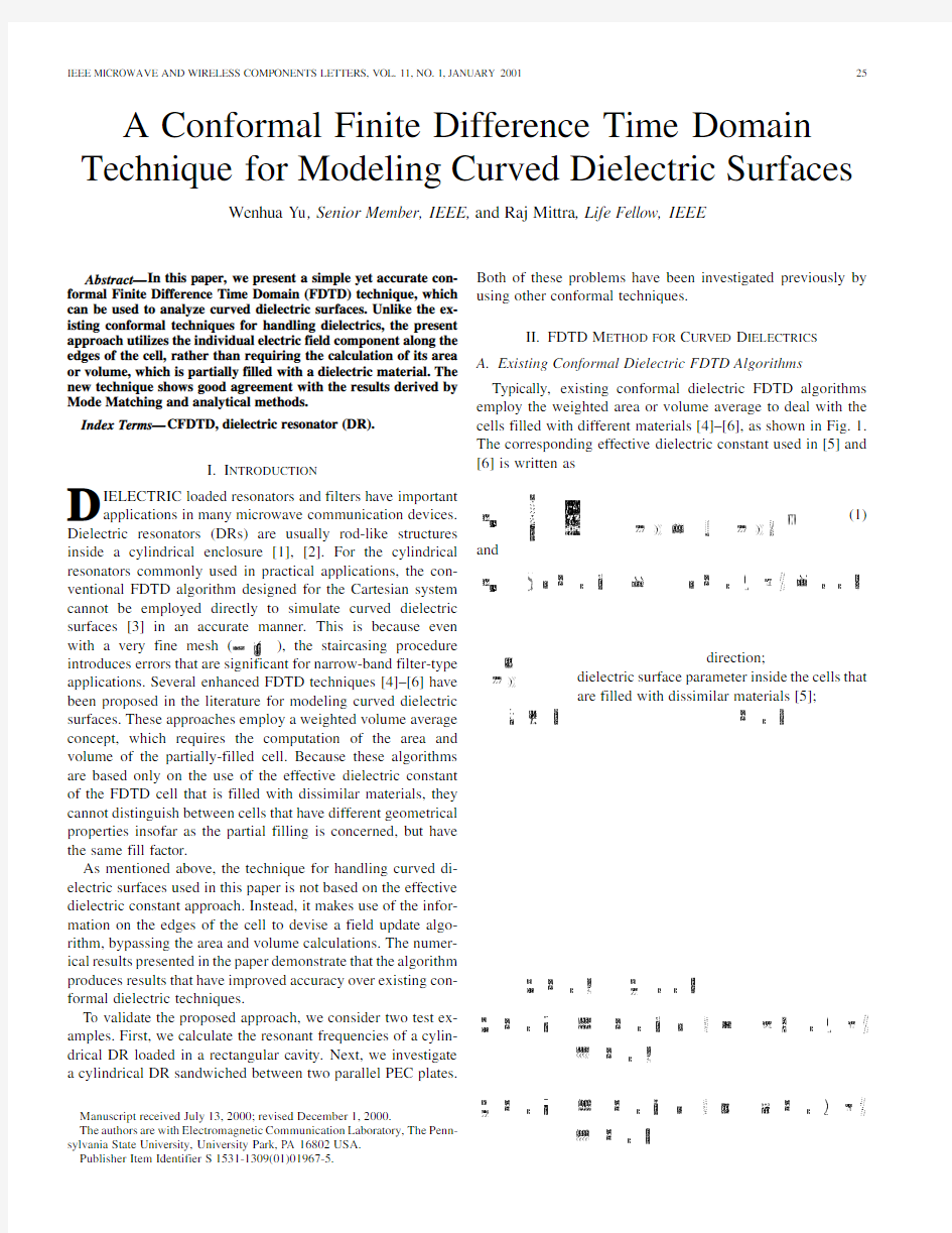
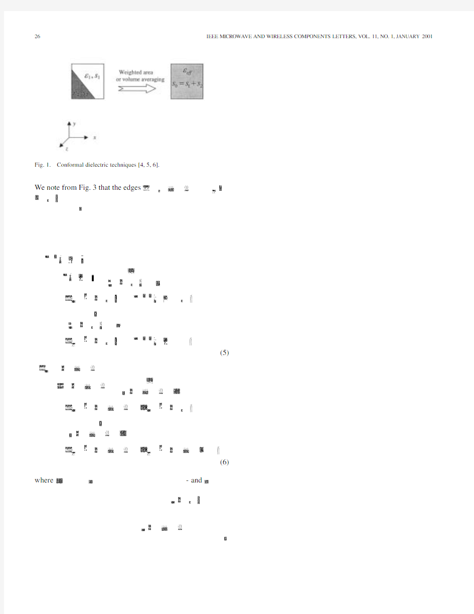
Typically,existing conformal dielectric FDTD algorithms employ the weighted area or volume average to deal with the cells filled with different materials [4]–[6],as shown in Fig.1.The corresponding effective dielectric constant used in [5]and [6]is written
as
(1)
and
direction;
dielectric surface parameter inside the cells that are filled with dissimilar materials
[5];
Fig.1.Conformal dielectric techniques[4,5,6].
We note from Fig.3that the edges
(5)
(6) where-and
YU AND MITTRA:CONFORMAL FDTD TECHNIQUE27 loaded with a cylindrical dielectric rod(Fig.4)as well as a
cylindrical DR sandwiched between two parallel PEC plates.
For both of these examples,the time step was taken to
be
(7)
We note from(7)that we do not have to compromise the Courant
condition in this algorithm.
Returning to the dielectric-loaded cavity problem in Fig.4,
we choose,for the sake of facilitating the comparison with pre-
viously published results,the relative dielectric constant of the
cylindrical rod to be38and assume that the pedestal below this
rod has a dielectric constant of1,in accordance with the spec-
ifications given in[1].Next,we generate a nonuniform mesh
via the mesh generation software available in[7].In the simu-
lation of the geometry1in Table I,the entire domain includes
4847cells,
the
and
46
and
46
and
-
and
and
HEM),for which the results given in both[5]and[6]deviate
noticeably from the theoretical values,are shown in Table II
below,along with those derived by using the present scheme.
TABLE I
C OMPARISON OF
D IFFERENT M ETHODS FOR A D IELECTRIC R OD IN A
R ECTANGULAR C A
VITY
TABLE II
C OMPARISON OF
D IFFERENT M ETHODS FOR A
DR
It is evident from the above table that the results obtained
via the present conformal dielectric scheme are in very good
agreement with the theoretical values.
IV.C ONCLUSION
A simple yet accurate scheme to model curved dielectric sur-
faces in the context of FDTD has been introduced in this paper.
The new updating scheme does not require area or volume cal-
culations,and is convenient to apply without the burden of cal-
culating the truncated cell areas and volumes which are partially
filled with a dielectric material.Hence,the mesh generation for
this conformal technique is quite simple.A more general av-
erage formulation may be employed to calculate the effective
dielectric constant for large difference between the two dielec-
tric constants.
R EFERENCES
[1]X.-P.Liang and K.A.Zakim,“Modeling of cylindrical dielectric res-
onators in rectangular waveguides and cavity,”IEEE Trans.Microwave
Theory Tech.,vol.41,no.12,pp.2174–2181,Dec.1993.
[2]S.J.Fiedziusko,“Dual-mode dielectric resonator loaded cavity filters,”
IEEE Trans.Microwave Theory Tech.,vol.MTT–30,no.9,pp.
1311–1316,Sept.1982.
[3]K.S.Yee,“Numerical solution of initial boundary value problems in-
volving Maxwell’s equations in isotropic media,”IEEE Trans.Antennas
Propagat.,vol.AP-14,pp.302–307,May1966.
[4]M.Celuch-Marcysiak and W.K.Gwarek,“Higher order modeling of
media surfaces for enhanced FDTD analysis of microwave circuits,”in
Proc.24th European Microwave Conf.,vol.2,Cannes,France,1994,pp.
1530–1535.
[5]N.Kaneda,B.Houshm,and T.Itoh,“FDTD analysis of dielectric res-
onators with curved surfaces,”IEEE Trans.Microwave Theory Tech.,
vol.45,no.9,pp.1645–1649,Sept.1997.
[6]S.Dey and R.Mittra,“A conformal finite-difference time-domain tech-
nique for modeling cylindrical dielectric resonators,”IEEE Trans.Mi-
crowave Theory Tech.,vol.47,no.9,pp.1737–1739,Sept.1999.
[7]W.Yu and R.Mittra,“A conformal FDTD software package modeling
antennas and microstrip circuit components,”IEEE Antennas Propagat.
Mag.,vol.42,no.5,pp.28–39,Oct.2000.
结构力学中必须掌握的弯矩图
各种结构弯矩图的绘制及图例: 一、方法步骤 1、确定支反力的大小和方向(一般情况心算即可计算出支反力) ●悬臂式刚架不必先求支反力; ●简支式刚架取整体为分离体求反力; ●求三铰式刚架的水平反力以中间铰C的某一边为分离体; ●对于主从结构的复杂式刚架,注意“先从后主”的计算顺序; ●对于复杂的组合结构,注意寻找求出支反力的突破口。 2、对于悬臂式刚架,从自由端开始,按照分段叠加法,逐段求作M图(M图画在受拉一侧);对于其它形式的刚架,从支座端开始,按照分段叠加法,逐段求作M图(M图画在受拉一侧)。 二、观察检验M图的正确性 1、观察各个关键点和梁段的M图特点是否相符 ●铰心的弯矩一定为零; ●集中力偶作用点的弯矩有突变,突变值与集中力偶相等;
●集中力作用点的弯矩有折角; ●均布荷载作用段的M 图是抛物线,其凹凸方向与荷载方向要符合“弓箭法则”; 2、结构中的链杆(二力杆)没有弯矩; 3、结构中所有结点的杆端弯矩必须符合平衡特点。 表1 简单载荷下基本梁的剪力图与弯矩图 梁的简图 剪力Fs 图 弯矩M 图 1 l a F s F F l a F l a l -+ - F l a l a ) (-+ M 2 l e M s F l M e + M e M + 3 l a e M s F l M e + M e M l a l -e M l a + -
4 l q s F + -2 ql 2 ql M 8 2ql + 2 l 5 l q a s F + -l a l qa 2) 2(-l qa 22 M 2 228)2(l a l qa -+ l a l qa 2) (2 -l a l a 2)2(- 6 l q s F + -3 0l q 6 0l q M 3 92 0l q + 3 )33(l - 7 a F l s F F + Fa -M 8 a l e M s F + e M M
结构力学中必须掌握的弯矩图
文档通用封面模板 本页面为作品封面,下载文档后可自 精吕文档 由编辑删除! 1
各种结构弯矩图的绘制及图例: 一、方法步骤 1、确定支反力的大小和方向(一般情况心算即可计算出支反力) ●悬臂式刚架不必先求支反力; ●简支式刚架取整体为分离体求反力; ●求三铰式刚架的水平反力以中间铰C的某一边为分离体; ●对于主从结构的复杂式刚架,注意“先从后主”的计算顺序; ●对于复杂的组合结构,注意寻找求出支反力的突破口。 2、对于悬臂式刚架,从自由端开始,按照分段叠加法,逐段求作M图(M图画在受拉一侧);对于其它形式的刚架,从支座端开始,按照分段叠加法,逐段求作M图(M图画在受拉一侧)。 2
3 二、 观察检验M 图的正确性 1、观察各个关键点和梁段的M 图特点是否相符 ●铰心的弯矩一定为零; ●集中力偶作用点的弯矩有突变,突变值与集中力偶相等; ●集中力作用点的弯矩有折角; ●均布荷载作用段的M 图是抛物线,其凹凸方向与荷载方向要符合“弓箭法则”; 2、结构中的链杆(二力杆)没有弯矩; 3、结构中所有结点的杆端弯矩必须符合平衡特点。 表1 简单载荷下基本梁的剪力图与弯矩图 梁的简图 剪力Fs 图 弯矩M 图 1 l a F s F F l a F l a l -+ - F l a l a ) (-+ M
4 2 l e M s F l M e + M e M + 3 l a e M s F l M e + M e M l a l -e M l a + - 4 l q s F + -2 ql 2 ql M 8 2ql + 2 l 5 l q a s F + -l a l qa 2) 2(-l qa 22 M 2 228)2(l a l qa -+ l a l qa 2) (2 -l a l a 2)2(- 6 l q s F + -3 0l q 6 0l q M 3 920l q + 3 )33(l -
结构力学弯矩图经典100题
静定结构弯矩图百绘制基本功强化训练 1 2 3 4 5 6 7 8 (8)(7) (5)(4) 一、梁 q M=PL 2P M L q L P PL 2PL P L/22M=qL q (9 (7) (6 (5) (4)(3 一、梁 M= q M=PL 2P M q L P L q L 2PL P L 2M=qL q (9)(8)(7) (6) (5) (4) (1) 、梁 2M=qL P=qL q q M=PL 2P q P=qL L q L L L L q P L L q PL 2PL P L L/2 2M=qL q L 7)(5)4)(3)(2)2 M=qL P=qL q q P=qL M=PL 2P q P=qL M L L 2P P L q P L P q L P L/22 M=qL (10)(4) 一、梁 q 2PL 2M=qL q ) (6) ) (3)2M=qL P=qL q P=qL q P=qL L L q q PL L (5)(4)(2) (1) 一、梁 q q q M=PL 2P L M q L L P L P L/2 2 M=qL q (1 (11) (10) (9)(8)(7)(6) (5) (4) (3) (2) (1) 一、梁 q q q M=q L q L L P L L P q L 2PL P L 2q
9 10 11 12 13 14 15 16 (20) (19) 二、悬臂式刚架 (18) P L /2 L/2 L/2L /2 30P L L M=2qa q 15 M=PL 二、悬臂式刚架 (18) (16) P L /2 L /2 30P L 4a 2a a a 2a 2a a 3a M=2qa q 15 M=PL (20) (19) 二、悬臂式刚架 P L /2 L/2 L/2L /2 30P L L M=2qa q a M=PL (15) (14) (13) (12) (11)(10) (9) (8) L/4 L/4q L L L q L P=qL L M L L L L L (14) (13) (12)(11) (10)(9) (7) L/4 L/4 q L L q L 2 M=qL L q L q M=PL 2P L L q L q L L (14 (13) (10) q L L (12) 11)(9) 8) L /2 L/4 P=qL L L q L P=qL M L
结构力学中必须掌握的弯矩图
结构力学中必须掌握的弯矩图
各种结构弯矩图的绘制及图例: 一、方法步骤 1、确定支反力的大小和方向(一般情况心算即可计算出支反力) ●悬臂式刚架不必先求支反力; ●简支式刚架取整体为分离体求反力; ●求三铰式刚架的水平反力以中间铰C的某一边为分离体; ●对于主从结构的复杂式刚架,注意“先从后主”的计算顺序; ●对于复杂的组合结构,注意寻找求出支反力的突破口。 2、对于悬臂式刚架,从自由端开始,按照分段叠加法,逐段求作M图(M图画在受拉一侧);对于其它形式的刚架,从支座端开始,按照分段叠加法,逐段求作M图(M图画在受拉一侧)。 二、观察检验M图的正确性 1、观察各个关键点和梁段的M图特点是否相符 ●铰心的弯矩一定为零; ●集中力偶作用点的弯矩有突变,突变值与集中力偶相等; 2
3
4 4 l q s F + - 2 ql 2 ql M 8 2ql + 2 l 5 l q a s F + - l a l qa 2) 2(-l qa 22 M 2 228)2(l a l qa -+ l a l qa 2) (2 -l a l a 2)2(- 6 l q s F + - 3 0l q 6 0l q M 3 92 0l q + 3 )33(l - 7 a F l s F F + Fa - M 8 a l e M s F + e M M
5 9 l q s F ql + M 2 2ql - 10 l q s F 2 l q + M 6 20l q - 注:外伸梁 = 悬臂梁 + 端部作用集中力偶的简支梁
2.单跨梁的内力及变形表(表2-6~表2-10)(1)简支梁的反力、剪力、弯矩、挠度表2-6
