UGF8JCT中文资料
UG8JCT,UGF8JCT,UGB8JCT Series
Vishay Semiconductors
formerly General Semiconductor
Document Number https://www.360docs.net/doc/ca432708.html,
New Product
Reverse Voltage 500 to 600V
Forward Current 8A
Reverse Recovery Time 25ns
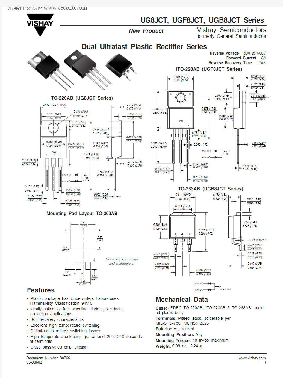
Mounting Pad Layout TO-263AB
Dimensions in inches and (millimeters)
ITO-220AB (UGF8JCT Series)
TO-220AB (UG8JCT Series)
TO-263AB (UGB8JCT Series)
Features
? Plastic package has Underwriters Laboratories Flammability Classification 94V-0
? Ideally suited for free wheeling diode power factor correction applications
? Soft recovery characteristics
? Excellent high temperature switching ? Optimized to reduce switching losses
? High temperature soldering guaranteed:250°C/10 seconds at terminals
? Glass passivated chip junction
Mechanical Data
Case:JEDEC TO-220AB, ITO-220AB & TO-263AB mold-ed plastic body
Terminals:Plated leads, solderable per MIL-STD-750, Method 2026Polarity:As marked Mounting Position:Any
Mounting Torque:10 in-lbs maximum Weight:0.08 oz., 2.24 g
UG8JCT,UGF8JCT,UGB8JCT Series
Vishay Semiconductors
formerly General Semiconductor
https://www.360docs.net/doc/ca432708.html, Document Number 88766
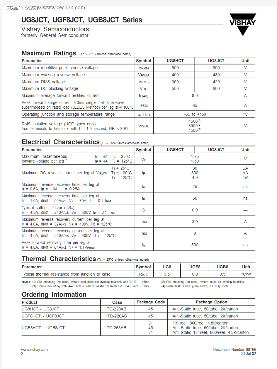
Maximum Ratings (T
C
= 25°C unless otherwise noted)
Parameter
Symbol UG8HCT UG8JCT Unit Maximum repetitive peak reverse voltage V RRM 500600V Maximum working reverse voltage V RWM 400480V Maximum RMS voltage V RMS 350420V Maximum DC blocking voltage
V DC 500
600
V Maximum average forward rectified current
I F(AV)8.0A Peak forward surge current 8.3ms single half sine-wave I FSM 65A superimposed on rated load (JEDEC Method) per leg at T C = 100°C Operating junction and storage temperature range T J , T STG –55 to +150°C RMS Isolation voltage (UGF types only)
4500(1)from terminals to heatsink with t = 1.0 second, RH ≤30%
V ISOL
3500(2)V
1500(3)
Electrical Characteristics (T
C
= 25°C unless otherwise noted)
Parameter
Symbol
UG8HCT
UG8JCT Unit Maximum instantaneous I F = 4A, T J = 25°C V F 1.75V forward voltage per leg (4)
I F = 4A, T J = 125°C
1.50T J = 25°C
30μA Maximum DC reverse current per leg at V RWM T J = 100°C
I R 800μA T J = 125°C 4.0mA Maximum reverse recovery time per leg at I F = 0.5A, I R = 1.0A, I rr = 0.25A
t rr 25ns Maximum reverse recovery time per leg at
t rr 50ns I F = 1.0A, di/dt = 50A/μs, V R = 30V , I rr = 0.1 I RM T ypical softness factor (t b /t a )
S 0.9—I F = 4.0A, di/dt = 240A/μs, V R = 400V , I rr = 0.1 I RM Maximum reverse recovery current per leg at I RM 3.0A I F = 4.0A, di/dt = 32A/μs, V R = 400V , T C = 125°C Maximum reverse recovery current per leg at
I RM 8A I F = 4.0A, di/dt = 240A/μs, V R = 400V , T C = 125°C Peak forward recovery time per leg at t fr
500
ns
I F = 4.0A, di/dt = 64A/μs, V F = 1.1V Fmax
Thermal Characteristics (T
C
= 25°C unless otherwise noted)
Parameter
Symbol UG8UGF8UGB8Unit T ypical thermal resistance from junction to case
R θJC
3.5
6.0
3.5
°C/W
Notes:(1) Clip mounting (on case), where lead does not overlap heatsink with 0.110”offset
(2) Clip mounting (on case), where leads do overlap heatsink (3) Screw mounting with 4-40 screw, where washer diameter is ≤ 4.9 mm (0.19”)(4) Pulse test:300μs pulse width, 1% duty cycle
Ordering Information
Product
Case Package Code
Package Option
UG8HCT - UG8JCT TO-220AB 45Anti-Static tube, 50/tube, 2K/carton UGF8HCT - UGF8JCT ITO-220AB 45Anti-Static tube, 50/tube, 2K/carton 3113”reel, 800/reel, 4.8K/carton
UGB8HCT - UGB8JCT
TO-263AB
45Anti-Static tube, 50/tube, 2K/carton
81
Anti-Static 13”reel, 800/reel, 4.8K/carton
UG8JCT,UGF8JCT,UGB8JCT Series
Vishay Semiconductors
formerly General Semiconductor
Document Number https://www.360docs.net/doc/ca432708.html,
Ratings and
Characteristic Curves (T A = 25°C unless otherwise noted)
1
100
10
P e a k F o r w a r d S u r g e C u r r e n t (A )
Number of Cycles at 60 H Z
12
10
6
82425
50
75
100
125
150
Fig. 1 -- Maximum Forward Current
Derating Curve
A v e r a g e F o r w a r d R e c t i f i e d C u r r e n t (A )
Case Temperature (°C)
Fig. 3 -- Typical Instantaneous Forward Characteristics Per Leg
Fig. 4 -- Typical Reverse Leakage
Characteristics Per Leg
0.01
0.1
10100
1I n s t a n t a n e o u s F o r w a r d C u r r e n t (A )
Reverse Voltage (V)
J u n c t i o n C a p a c i t a n c e (p F )
1
10
100
100
10
1255075100125150
T J , Junction Temperature (°C)
Fig. 2 -- Maximum Non-Repetitive Peak
Forward Surge Current Per Leg
020
40
60
80
100