MBR30H150CTG;MBRF30H150CTG;中文规格书,Datasheet资料
MBRF30H150CTG,MBR30H150CTG SWITCHMODE ?Power Rectifier 150 V , 30 A
Features and Benefits
?Low Forward V oltage
?Low Power Loss/High Efficiency ?High Surge Capability
?30 A Total (15 A Per Diode Leg)?Guard ?Ring for Stress Protection ?
These are Pb ?Free Devices
Applications
?Power Supply ? Output Rectification ?Power Management ?Instrumentation
Mechanical Characteristics:
?Case: Epoxy, Molded
?Epoxy Meets UL 94 V ?0 @ 0.125 in
?Weight (Approximately): 1.9 Grams (TO ?220 & TO ?220FP)?Finish: All External Surfaces Corrosion Resistant and Terminal Leads are Readily Solderable
?
Lead Temperature for Soldering Purposes:260°C Max. for 10 Seconds
MAXIMUM RATINGS
Please See the Table on the Following Page
TO ?220AB CASE 221A STYLE 6
SCHOTTKY BARRIER
RECTIFIER
30 AMPERES, 150 VOLTS
1
3
2, 4
MARKING DIAGRAMS
A = Assembly Location Y = Year
WW
= Work Week B30H150= Device Code G = Pb ?Free Device AKA
= Polarity Designator
https://www.360docs.net/doc/c218312431.html,
?220 FULLPAK ]
CASE 221D STYLE 3
See detailed ordering and shipping information in the package dimensions section on page 2 of this data sheet.
ORDERING INFORMATION
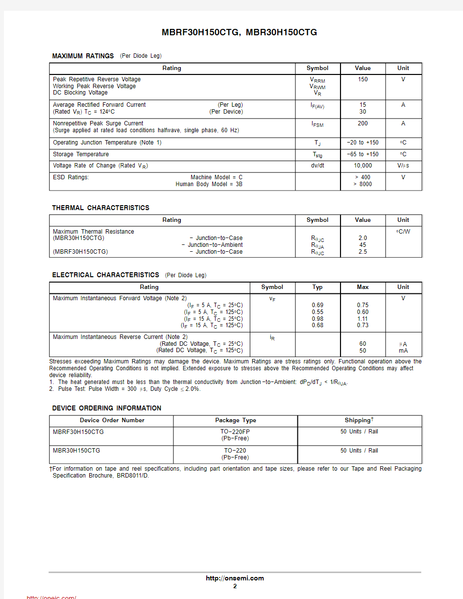
MAXIMUM RATINGS (Per Diode Leg)
Rating Symbol Value Unit
Peak Repetitive Reverse Voltage Working Peak Reverse Voltage DC Blocking Voltage V RRM
V RWM
V R
150V
Average Rectified Forward Current(Per Leg) (Rated V R) T C = 124°C(Per Device)I F(AV)15
30
A
Nonrepetitive Peak Surge Current
(Surge applied at rated load conditions halfwave, single phase, 60 Hz)
I FSM200A Operating Junction Temperature (Note 1)T J?20 to +150°C Storage Temperature T stg?65 to +150°C Voltage Rate of Change (Rated V R)dv/dt10,000V/m s
ESD Ratings:Machine Model = C
Human Body Model = 3B > 400
> 8000
V
THERMAL CHARACTERISTICS
Rating Symbol Value Unit
Maximum Thermal Resistance
(MBR30H150CTG)? Junction?to?Case
? Junction?to?Ambient (MBRF30H150CTG)? Junction?to?Case R q JC
R q JA
R q JC
2.0
45
2.5
°C/W
ELECTRICAL CHARACTERISTICS (Per Diode Leg)
Rating Symbol Typ Max Unit
Maximum Instantaneous Forward Voltage (Note 2)
(I F = 5 A, T C = 25°C)
(I F = 5 A, T C = 125°C)
(I F = 15 A, T C = 25°C)
(I F = 15 A, T C = 125°C)v F
0.69
0.55
0.98
0.68
0.75
0.60
1.11
0.73
V
Maximum Instantaneous Reverse Current (Note 2)
(Rated DC Voltage, T C = 25°C)
(Rated DC Voltage, T C = 125°C)i R
60
50
m A
mA
Stresses exceeding Maximum Ratings may damage the device. Maximum Ratings are stress ratings only. Functional operation above the Recommended Operating Conditions is not implied. Extended exposure to stresses above the Recommended Operating Conditions may affect device reliability.
1.The heat generated must be less than the thermal conductivity from Junction?to?Ambient: dP D/dT J < 1/R q JA.
2.Pulse Test: Pulse Width = 300 m s, Duty Cycle ≤2.0%.
DEVICE ORDERING INFORMATION
Device Order Number Package Type Shipping?
MBRF30H150CTG TO?220FP
(Pb?Free)
50 Units / Rail
MBR30H150CTG TO?220
(Pb?Free)
50 Units / Rail
?For information on tape and reel specifications, including part orientation and tape sizes, please refer to our Tape and Reel Packaging Specification Brochure, BRD8011/D.
I F , I N S T A N T A N E O U S F O R W A R D C U R R E N T (A )
Figure 1. Typical Forward Voltage V F , INSTANTANEOUS FORWARD VOLTAGE (V)
0.1
10
100
I F , I N S T A N T A N E O U S F O R W A R D C U R R E N T (A )
Figure 2. Maximum Forward Voltage
V F , INSTANTANEOUS FORWARD VOLTAGE (V)
0.1
1
10
100
I R , R E V E R S E C U R R E N T (A )Figure 3. Typical Reverse Current V R , REVERSE VOLTAGE (V)
1.0E ?1.0E ?1.0E ?1.0E ?1.0E ?1.0E ?R Figure 4. Maximum Reverse Current
V R , REVERSE VOLTAGE (V)
1.0E ?1.0E ?1.0E ?1.0E ?1.0E ?1.0E ?I F , A V E R A G E F O R W A R D C U R R E N T (A M P S )
Figure 5. Current Derating T C , CASE TEMPERATURE (°C)
P F O , A V E R A G E P O W E R D I S S I P A T I O N
(W A T T S )
I O , AVERAGE FORWARD CURRENT (AMPS)
Figure 6. Forward Power Dissipation
C , C A P A C I T A N C E (p F )
V R , REVERSE VOLTAGE (V)
Figure 7. Capacitance
10100
1000
10000
50
100
150
R (t ), T R A N S I E N T T H E R M A L R E S I S T A N C E
Figure 8. Thermal Response Junction ?to ?Ambient for MBR30H150CTG
1000
0.1
0.00001
t 1, TIME (sec)
1
0.0001
0.001
0.011
10
100
0.000001
0.1
10
100
R (t ), T R A N S I E N T T H E R M A L R E S I S T A N C E
Figure 9. Thermal Response Junction ?to ?Case for MBR30H150CTG
t 1, TIME (sec)
0.01
R (t ), T R A N S I E N T T H E R M A L R E S I S T A N C E
Figure 10. Thermal Response Junction ?to ?Case for MBRF30H150CTG
t 1, TIME (sec)
0.1
0.01
1
10
0.001
PACKAGE DIMENSIONS
TO ?220 FULLPAK CASE 221D ?03
ISSUE K
STYLE 3:
PIN 1.ANODE
2.CATHODE
3.ANODE
DIM A MIN MAX MIN MAX MILLIMETERS
0.6170.63515.6716.12INCHES B 0.3920.4199.9610.63C 0.1770.193 4.50 4.90D 0.0240.0390.60 1.00F 0.1160.129 2.95 3.28G 0.100 BSC 2.54 BSC H 0.1180.135 3.00 3.43J 0.0180.0250.450.63K 0.5030.54112.7813.73L 0.0480.058 1.23 1.47N 0.200 BSC 5.08 BSC Q 0.1220.138 3.10 3.50R 0.0990.117 2.51 2.96S 0.0920.113 2.34 2.87U
0.2390.271
6.06 6.88
SEATING PLANE
NOTES:
1.DIMENSIONING AND TOLERANCING PER ANSI Y14.5M, 198
2.
2.CONTROLLING DIMENSION: INCH
3.221D-01 THRU 221D-02 OBSOLETE, NEW STANDARD 221D-03.
M
B
M
0.25 (0.010)Y
TO ?220CASE 221A ?09ISSUE AF
NOTES:
1.DIMENSIONING AND TOLERANCING PER ANSI Y14.5M, 198
2.
2.CONTROLLING DIMENSION: INCH.
3.DIMENSION Z DEFINES A ZONE WHERE ALL BODY AND LEAD IRREGULARITIES ARE ALLOWED.
STYLE 6:
PIN 1.
ANODE 2.CATHODE 3.ANODE 4.
CATHODE
DIM MIN MAX MIN MAX MILLIMETERS INCHES A 0.5700.62014.4815.75B 0.3800.4059.6610.28C 0.1600.190 4.07 4.82D 0.0250.0350.640.88F 0.1420.161 3.61 4.09G 0.0950.105 2.42 2.66H 0.1100.155 2.80 3.93J 0.0140.0250.360.64K 0.5000.56212.7014.27L 0.0450.060 1.15 1.52N 0.1900.210 4.83 5.33Q 0.1000.120 2.54 3.04R 0.0800.110 2.04 2.79S 0.0450.055 1.15 1.39T 0.2350.255 5.97 6.47U 0.0000.0500.00 1.27V 0.045--- 1.15---Z
---0.080--- 2.04
F
SEATING PLANE
ON Semiconductor and are registered trademarks of Semiconductor Components Industries, LLC (SCILLC). SCILLC reserves the right to make changes without further notice to any products herein. SCILLC makes no warranty, representation or guarantee regarding the suitability of its products for any particular purpose, nor does SCILLC assume any liability arising out of the application or use of any product or circuit, and specifically disclaims any and all liability, including without limitation special, consequential or incidental damages.“Typical” parameters which may be provided in SCILLC data sheets and/or specifications can and do vary in different applications and actual performance may vary over time. All operating parameters, including “Typicals” must be validated for each customer application by customer’s technical experts. SCILLC does not convey any license under its patent rights nor the rights of others. SCILLC products are not designed, intended, or authorized for use as components in systems intended for surgical implant into the body, or other applications intended to support or sustain life, or for any other application in which the failure of the SCILLC product could create a situation where personal injury or death may occur. Should Buyer purchase or use SCILLC products for any such unintended or unauthorized application, Buyer shall indemnify and hold SCILLC and its officers, employees, subsidiaries, affiliates,and distributors harmless against all claims, costs, damages, and expenses, and reasonable attorney fees arising out of, directly or indirectly, any claim of personal injury or death associated with such unintended or unauthorized use, even if such claim alleges that SCILLC was negligent regarding the design or manufacture of the part. SCILLC is an Equal Opportunity/Affirmative Action Employer. This literature is subject to all applicable copyright laws and is not for resale in any manner.
PUBLICATION ORDERING INFORMATION
FULLPAK and SWITCHMODE are trademarks of Semiconductor Components Industries, LLC.
分销商库存信息:
ONSEMI
MBR30H150CTG MBRF30H150CTG