空冷器使用维护说明书(英文)
空冷风机使用维护说明

技
3.2.安装准备 a) 清理主轴、锥套及轮毂的配合表面。 b) 检查主轴是否垂直。如果垂直误差超过 0.5°则必需加以校正 c) 确保主轴与风筒同轴,同轴度误差不大于 5mm。 3.3.安装步骤
在任何风机组装前,要确保电机不会被意外启动。切断电机电源并按如下 步骤安装: a) 将锥套(4)滑装到主轴(14)上。 b) 将轮毂板(1)及锥套座(3)(出厂前以组装好)安装到锥套(4)上。 c) 确保锥套(4)法兰边上的螺栓孔与锥套座(3)上的螺纹孔对齐。穿上螺 栓逐步拧紧,最终拧紧力矩 40-50N M。使轮毂抱紧在传动轴上。 4.叶片的安装: a) 将上压块(7)从轮毂上移开,将叶轴放入下压块(2)槽中。 b) 叶片前缘(厚边)必需朝向指定的旋转方向。 c) 扣上上压块(7)穿入 U 形螺栓(5)并安装垫圈(8)及锁紧螺母(9),手
目录
航
技
2 2 2 3 3 3 6 8 9 11 11 11 12
1
保定航技风机制造有限公司
BAODING HJ FAN MANUFACTURING CO., LTD.
航
技
一.总述
1.风机简介: 风机总成含叶轮及传动系统。叶轮由锻铝合金叶片碳钢轮毂两部分组成。
传动系统包括电机架、驱动带轮、从动带轮、上下轴承座、主轴及传动带。风 机的构架或基础均应有足够的强度、刚度和稳定性,能吸收和隔离振动,防止 发生共振。 2. 风机铭牌说明:
盘动主轴,主轴应转动自如,力度均匀。
e) 安装加油管至轴承座,见图 7。油管为铜管。安装时应清除管口毛刺及管内
4
保定航技风机制造有限公司
BAODING HJ FAN MANUFACTURING CO., LTD.
航
技
西屋空调使用手册-英文说明书

ENGLISHBefore operating the unit, read these operatinginstructions thoroughly and keep them for futurereference.Operating InstructionsAir Conditioner Model No.Indoor Unit Outdoor UnitCS-S9NKUA CU-S9NKUACS-S12NKUA CU-S12NKUAF568315© Panasonic Appliances Air-Conditioning Malaysia Sdn. Bhd. 2012. Unauthorized copying and distribution is a violation of law.2Thank you for purchasing Panasonic Air Conditioner TABLE OF CONTENTS SAFETY PRECAUTIONS2~3REMOTE CONTROL4~5INDOOR UNIT6TROUBLESHOOTING7INFORMATION8QUICK GUIDEBACK COVERNOTEThe illustrations in this manual are for explanation purposes only and may differ from the actual unit. They are subjected to change without notice for future improvement.SAFETY PRECAUTIONSTo prevent personal injury, injury to others, or property damage, please comply with the following.Incorrect operation due to failure to follow instructions below may cause harm or damage, the seriousness of which is classi fi ed as below:WARNINGThis sign warns of death orserious injury.CAUTIONThis sign warns of injury or damage to property.The instructions to be followed are classi fi ed by the following symbols:This symbol denotes an actionthat is PROHIBITED.These symbols denote an actions that is COMPULSORY.WARNINGINDOOR UNIT AND OUTDOOR UNITThis appliance is not intended for use by persons (including children) with reduced physical, sensory or mental capabilities, or lack of experience and knowledge, unless they have been given supervision or instruction concerning use of the appliance by a person responsible for their safety. Children should be supervised to ensure that they do not play with the appliance.Please consult authorized dealer or specialist to clean the internal parts, repair, install, remove and reinstall the unit. Improper installation and handling will cause leakage, electric shock or fi re.Con fi rm to authorized dealer or specialist on usage of speci fi ed refrigerant type. Using of refrigerant other than the speci fi ed type may cause product damage, burst and injury etc.Do not install the unit in a potentially explosive or fl ammable atmosphere. Failure to do so could result in fi re.Do not insert your fi ngers or other objects into the air conditioner indoor or outdoor unit, rotating parts may cause injury.Do not touch the outdoor unit during lightning, it may cause electric shock.Do not expose yourself directly to cold air for a long period to avoid excess cooling.Do not sit or step on the unit, you may fall down accidentally.Air InletAir OutletAir OutletAir InletOutdoor UnitPower SupplyRemoteControlOPERATION CONDITION Use this air conditioner under the following temperature range Temperature (°F)Indoor *DBT *WBT COOLINGMax.89.673.4Min.60.851.8Temperature (°F)Outdoor *DBT *WBT COOLINGMax.109.478.8Min.5.0-* DBT : Dry bulb temperature * WBT : Wet bulb temperature POWER SUPPLYModels NumberTime Delay Circuit Breaker Rated VoltsCS/CU-S9NKUA 15 Amps 208/230V CS/CU-S12NKUA 15 Amps Indoor Unit3CAUTIONINDOOR UNIT AND OUTDOOR UNITDo not wash the indoor unit with water, benzene, thinner or scouring powder to avoid damage or corrosion at the unit.Do not use for preservation of precise equipment, food, animals, plants, artwork or other objects. This may cause quality deterioration, etc.Do not use any combustible equipment in front of the air fl ow outlet to avoid fi re propagation.Do not expose plants or pet directly to air fl ow to avoid injury, etc.Do not touch the sharp aluminium fi n, sharp parts may cause injury.Do not switch ON the indoor unit when waxing the fl oor. After waxing, aerate the room properly before operating the unit.Do not install the unit in oily and smoky areas to prevent damage to the unit.Do not dismantle the unit for cleaning purpose to avoid injury.Do not step onto an unstable bench when cleaning the unit to avoid injury.Do not place a vase or water container on the unit. Water may enter the unit and degrade the insulation. This may cause an electric shock.Do not open window or door for long time during COOL/DRY mode operation.Ensure drainage pipe is connected properly and keep drainage outlet clear of gutters, containers or does not immersed in water to prevent water leakage.After a long period of use or use with anycombustible equipment, aerate the room regularly.After a long period of use, make sure theinstallation rack does not deteriorate to prevent the unit from falling down.REMOTE CONTROLDo not use rechargeable (Ni-Cd) batteries.It may damage the remote control.To prevent malfunction or damage of the remote control:• Remove the batteries if the unit is not going to be used for a long period of time.• New batteries of the same type must be inserted following the polarity stated.WARNINGREMOTE CONTROLDo not allow infants and small children to play with the remote control to prevent them from accidentally swallowing the batteries.POWER SUPPLYDo not use a modi fi ed cord, joint cord, extension cord or unspeci fi ed cord to prevent overheating and fi re.To prevent overheating, fi re or electric shock:• Do not share the same power outlet with other equipment.• Do not operate with wet hands.• Do not over bend the power supply cord.If the supply cord is damage, it must be replaced by the manufacturer, its service agent or similarly quali fi ed persons in order to avoid a hazard.It is strongly recommended to install this unit using an Earth Leakage Circuit Breaker (ELCB) or Ground Fault Interrupt (GFCI) or ApplianceLeakage Current Interrupt (ALCI) to prevent electric shock or fi re.Stop using the product if any abnormality/failure occurs or turn off the power switch and breaker.(Risk of smoke/fi re/electric shock)Examples of abnormality/failure• The ELCB or GFCI or ALCI trip frequently. • Burning smell is observed.• Abnormal noise or vibration of the unit is observed.• Water leaks from the indoor unit. • Power cord becomes abnormally hot.• Fan speed cannot be controlled.• The unit stops running immediately even if it is switched on for operation.• The fan does not stop even if the operation is stopped.Contact your local dealer immediately for maintenance or repair assistance.This equipment must be earthed to prevent electrical shock or fi re.Prevent electric shock by switching off the power:- Before cleaning or servicing.- Extended non-use.- Abnormally strong lightning activity.4REMOTE CONTROLMaximum distance: 26ftINDICATORPOWER (Green) TIMER (Orange) QUIET (Orange)POWERFUL (Orange)A U T O C O O L D R YF A N S P E E D A IR S W IN GF A N S PE E DA IR S WINGM O D EQ U IE T T E M PO F F /ONP O W E RF U LT IM E R S E TC A N CE LO NO F F123342RemoteControl display6571Press the remote control’s button 1TO TURN ON OR OFF THE UNIT• Please be aware of the OFF indication on the remote control display to prevent the unit from starting/stopping improperly.2TO SET TEMPERATURE• Selection range : 60°F ~ 86°F.• Operating the unit within the recommended temperature could induce energy saving.COOL mode : 78°F ~ 82°F.DRY mode : 2°F ~ 4°F lower than room temperature.3TO SELECT OPERATION MODEAUTO mode - For your convenience• During operation mode selection the power indicator blinks.• Unit selects operation mode every 10 minutes according to temperature setting and room temperature.COOL mode - To enjoy cool air• Use curtains to screen off sunlight and outdoor heat to reduce power consumption during cool mode.DRY mode - To dehumidify the environment• Unit operates at low fan speed to give a gentle cooling operation.4TO SELECT FAN SPEED (5 OPTIONS)FAN SPEED• For AUTO, the indoor fan speed is automatically adjusted according to the operation mode.5TO ADJUST VERTICAL AIRFLOW DIRECTION (5 OPTIONS)AIR SWING• Keeps the room ventilated.• In COOL/DRY mode, if AUTO is set, the louver swing up/down automatically.6TO ENJOY QUIET OPERATION• This operation reduces air fl ow noise.7TO REACH TEMPERATUREQUICKLY• This operation stops automatically after 20 minutes.891210118Press and hold for 5 seconds to dim or restore the unit’s indicator brightness.9Press and hold for approximately 10 seconds to show temperature setting in °C or °F10Press and hold for approximately 5 seconds to show 12-hour (am/pm) or 24-hour time indication.11Press to restore the remote control’s default setting. 12Not used in normal operations.NOTESQUIET,POWERFUL• Can be activated in all modes and can be cancelled by pressing the respective button again.QUIET,POWERFUL• Cannot be selected at the same time.TO SET THE TIMER• To turn ON or OFF the unit at a preset time.ONOFF12SETSelect ON orOFF timer Set the time Confi rm• To cancel ON or OFF timer, press ON or OFF then press CANCEL.• When ON Timer is set, the unit may start earlier (up to 15 minutes) before the actual set time in order to achieve the desired temperature on time.• Timer operation is based on the clock set in the remote control and repeats daily once set. For clock setting, please refer to Remote Control Preparation on the back cover.• If timer is cancelled manually or due to power failure, you can restore the previous setting (once power is resumed) by pressing SET.56CAUTION• Switch off the power at the circuit breaker before cleaning.• Do not touch the aluminium fi n, sharp parts may cause injury.CLEANING INSTRUCTIONSHINT• Do not use benzene, thinner or scouring powder.• Use only soap ( pH7) or neutral household detergent.• Do not use water hotter than 104°F.• To ensure optimal performance of the unit, cleaning maintenance has to be carried out at regular intervals. Dirty unit may cause malfunction and you may see error code “H99”. Please consult authorized dealer.INDOOR UNIT2567143981INDOOR UNIT • Wipe the unit gently with a soft, dry cloth.2FRONT PANELRemove Front Panel• Raise and pull to remove the front panel.• Wash gently and dry.Close Front Panel• Press down both ends of the front panel to close it securely.3REMOTE CONTROL RECEIVER 4ALUMINIUM FIN5HORIZONTAL AIRFLOW DIRECTION LOUVER• Manually adjustable.6VERTICAL AIRFLOW DIRECTION LOUVER• Do not adjust by hand.7AUTO OFF/ON BUTTON• Use when remote control is misplaced or a malfunction occurs.Step Action Mode 1Press once.Automatic2Press and hold until you hear one beep, then release.Force cooling3Repeat step 2. Press and hold until you hear two beeps, then release.Normal coolingPress the button to turn off.8AIR PURIFYING FILTERVacuum the air purifying fi lter.• It is recommended to clean the fi lter every 6 months.• Replace the fi lter every 3 years or replace any damaged fi lter.Part no.: CZ-SA20P 9AIR FILTERS• Air fi lter cleaning is required every two weeks.• Wash/rinse the fi lters gently with water to avoid damage to the fi lter surface.• Dry the fi lters thoroughly under shade, away from fi re or direct sunlight.• Replace any damaged fi lters.7The unit stops and the TIMER indicator e remote control to retrieve error code.TIMER SET CANCELON OFF 1231Press for 5seconds.3Press for 5 seconds to quit checking.2Press until you hear beep sound, then write down the error code.Note:• For certain errors, you may restart the unit for limited operation with 4 beeps when operation starts.4Turn the unit off and reveal the error code to authorized dealer.TROUBLESHOOTINGThe following symptoms do not indicate malfunction.SYMPTOMCAUSEMist emerges from indoor unit.►• Condensation effect due to cooling process.Water fl owing sound during operation.►• Refrigerant fl ow inside the unit.The room has a peculiar odor.►• This may be due to damp smell emitted by the wall,carpet, furniture or clothing.Indoor fan stops occasionally during automatic fan speed setting.►• This helps to remove the surrounding odours.Operation is delayed a few minutes after restarting.►• The delay is a protection to the unit’s compressor.Outdoor unit emits water/steam.►• Condensation or evaporation occurs on pipes.TIMER indicator is always on.►• The timer setting repeats daily once set.POWER indicator blinks before the unit is switched on.►• This is a preliminary step in preparation for the operation when the ON timer has been set.Cracking sound during operation.►• Changes of temperature caused the expansion/contraction of the unit.Check the following before calling for servicing.SYMPTOMCHECKCooling operation is not working ef fi ciently.►• Set the temperature correctly.• Close all doors and windows.• Clean or replace the fi lters.• Clear any obstruction at the air inlet and air outlet vents.Noisy during operation.►• Check if the unit has been installed at an incline.• Close the front panel properly.Remote control does not work.(Display is dim or transmission signal is weak.)►• Insert the batteries correctly.• Replace weak batteries.The unit does not work.►• Check if the circuit breaker is tripped.• Check if timers have been set.The unit does not receive the signal from the remote control.►• Make sure the receiver is not obstructed.• Certain fl uorescent lights may interfere with signal transmitter. Please consult authorized dealer.INFORMATIONFOR SEASONAL INSPECTION AFTER EXTENDED NON-USE• Check remote control batteries.• No obstruction at air inlet and air outlet vents.• Use Auto OFF/ON button to select Cooling operation. After 15 minutes of operation, it is normal to have the following temperature difference between air inlet and air outlet vents:Cooling: ≥ 14.4°FFOR EXTENDED NON-USE• Switch off power at the circuit breaker.• Remove the remote control batteries.NON SERVICEABLE CRITERIASSWITCH OFF POWER AT THE CIRCUIT BREAKER then please consult an authorized dealer under the following conditions:• Abnormal noise during operation.• Water/foreign particles have entered the remote control.• Water leaks from Indoor unit.• Circuit breaker switches off frequently.• Switches or buttons are not functioning properly.Information for Users on Collection and Disposal of Old Equipment and used Batteries[Information on Disposal in other Countries outside the European Union]These symbols are only valid in the European Union. If you wish to discard these items, please contact your local authorities or dealer and ask for the correct method of disposal.Note for the battery symbol (bottom twosymbol examples):This symbol might be used in combination witha chemical symbol. In this case it complies withthe requirement set by the Directive for thechemical involved.PbContact your local hazardous waste disposal hotline.Models Number CS-S9NKUA / CU-S9NKUA CS-S12NKUA / CU-S12NKUAThe above listed models have been designed and manufactured to meet ENERGY STAR® criteria forenergy effi ciency when matched with appropriate coil components. However, proper refrigerant chargeand proper air fl ow are critical to achieve rated capacity and effi ciency. Installation of this product shouldfollow the manufacturer’s refrigerant charging and airfl ow instructions. Failure to confi rm proper charge andairfl ow may reduce energy effi ciency and shorten equipment life.Federal Communications Commission Interference StatementThis device complies with part 15 of the FCC Rules. Operation is subject to the following two conditions: (1) This device may not cause harmful interference, and (2) this device must accept any interference received, including interference that may cause undesired operation.This equipment has been tested and found to comply with the limits for a Class B digital device, pursuant to part 15 of the FCC Rules. These limits are designed to provide reasonable protection against harmful interference in a residential installation. This equipment generates, uses and can radiate radio frequency energy and, if not installed and used inaccordance with the instructions, may cause harmful interference to radio communications. However, there is no guarantee that interference will not occur in a particular installation. If this equipment does cause harmful interference to radio or television reception, which can be determined by turning the equipment off and on, the user is encouraged to try to correct the interference by one or more of the following measures:• Reorient or relocate the receiving antenna.• Increase the separation between the equipment and the receiver.• Connect the equipment to an outlet on a circuit different from that to which the receiver is connected.• Consult the dealer or an experienced radio/TV technician for help.FCC Caution: To assure continued compliance, follow the attached installation instructions. Any changes or modifi cations not expressly approved by the party responsible for compliance could void the user’s authority to operate this equipment.Industry Canada NoticeThis Class B digital apparatus complies with Canadian ICES-003.8MEMOQUICK GUIDEAUTOCOOLDRYFANSPEEDAIRSWINGFAN SPEEDAIR SWINGMODEQUIETTEMPOFF/ONPOWERFULTIMERSETCANCELONOFF123213Remote Control Preparation123TIMERSETCANCELONOFF1234561Pull out2Insert AAA or R03 batteries (can be used ~ 1 year)3Close the cover4Press CLOCK5Set time6Confi rmMODEAUTODRY COOLSelect the desired mode.1OFF/ONStart/stop the operation.2TEMPSelect the desired temperature.3Printed in MalaysiaPanasonic CorporationWebsite: /For inquiries, please call 1-800-851-1235F568315SS1211-1。
松芝空调英文使用维护手册

Company profileShanghai Jialeng Songz Automobile Air-Condition Co. L TD (Hereinafter as SONGZ) invested by Hongkong Yi-fu-rong-xing Co. L TD of $30,000,000, is a single venture company sited in Shanghai Xinzhuang Industrial Development Zone. SONGZ focuses on R&D, manufacture and sales of automobile air conditioner with the brand name marked ‘SONGZ’ or ‘松芝’.With an area of 20,000 m2, located on No.4999, Huaning Rd., Shanghai Xinzhuang Industrial Development Zone, SONGZ has a complete A/C set of product machines and test devices, which represent the advanced level in China, including the domestic largest bus air conditioner bench test apparatus (With the cooling capacity of 40,000 Kcal/H).SONGZ has attracted lots of excellent automobile A/C engineers, thus owns a powerful R&D ability. It can design and offer high-quality products to satisfy the customers entirely according to their various demands for different buses.Our main products are bus roof-mounted air conditioners, including LUX/BBP/HLB/JLC series adopted in 7~14m long buses, SZA series (7~12m), and APP series (6~14m), bus inner-roof-combined-mounted series (6~14m).Dedication to the Improvement of Mankind’s Living-ConditionSONGZ Bus Air Conditioner—The Moving SpringCatalogue◇Preface 2◇Attention 3◇Product Introduction 4◇A/C Operation and Maintenance 7◇A/C Service 13◇A/C Trouble Analysis and Elimination 22◇The System of SONGZ Service Stations 29PrefacePlease read the handbook carefully to make sure using our products correctly.The context of the handbook is mainly about the operation, maintenance and service of SONGZ Roof-mounted Bus Air Conditioners.The information offered in this handbook may not complete. Please contact our customer service department or service station, and you’ll get a satisfied feedback.SONGZ Service Hot Line:0086-21-54422057◆Please give the handbook to the driver.◆Please refer to the common trouble information in the handbook and contact thecustomer service department or service station of SONGZ, when your bus air conditioner fails to work.◆Please keep the handbook properly in the bus so as to use it at any moment.◆The handbook is only for reference, and any modification would not be informed of.SONGZ sincerely appreciates your further advices and suggestions for our products and service.CHAPTER 1 ATTENTION1.1 Safety Pr ocee di ngs1)Shut off A/C power swi tch i mmediatel y when A/C alarms.2)Strictl y pr ohi bi t tou chi ng the r otati ng com ponent s (fan s, belts, pulleys, etc.) an d h ot par ts(com pre ssor, hi gh pre ssure h ose, et c.) of A/C, when A/C i s runni ng or power-off.3)A/C el ectri cal a ppl i ance are stri ctly pr ohi bi ted w orki ng with water on.4)Unpr ofe ssi onal te chni ci ans coul dn’t t ou ch A/C f or fea r tha t any a cci dent occur s.1.2 U se Comf orta bl y1)Please park the A/C bu s i n the cool and draughty place.2)Please cl ose bu s door s, wi ndow s an d the venti l ati on fa ciliti es when A/C i s running.3)Please mai ntai n A/C a ccor di ng t o ‘Mai ntenan ce C alenda r’ i n the han dbook.1.3 The Servi ce Rul e s f or Cu st omer s1)Please fi l l i n <<SONGZ Servi ce Tra ck Car d>> i n detail s an d mai l i t to the cu stomer servi cede partment of SON GZ i n or der to create cu stomer fi les on ce the bu s bei ng pur cha se d, so that your l egal ri ghts could be pr ote cte d.2)Please conta ct the cu st omer servi ce de partment or servi ce station of SON GZ, when y our bu s aircon di ti oner nee ds re pai r.3)We w oul d n ot take any re spon si bi li ty for the tr ou bles cau se d by impr oper in stall ation an d wr ongoperati on.W arnin g:The occurred troubles are not listed on the guarantee provisions if A/C is disassembled and maintained by yourself or non-SONGZ-engaged service agencies without permission, even though you have the guarantee card.Chapter 2 Product Introduction1.1 Summaryfigure good-looking.2)The interior components of A/C match well to make sure that the A/C systemcould get a higher refrigeration coefficient (COP).3)Choosing an appropriate fresh air device, which can provide 10~20% fresh airfrom outside to make the passengers comfortable.4)The use of the ozone-friendly refrigerant, HFC134a, can reduce the pollution toour environment to a maximal extent.5)The main components of A/C include a roof-mounted evaporator & condenserass’y, a compressor ass’y, hose &pipe (H&P) and a control panel. The evaporator & condenser ass’y is installed at the top of the bus.1.2 A/C Total Layout1.3 A/C technical parametersThe Chart of Basic types of SZA /BBP /JLC Series for SONGZ A/C Coach & TouringBusThe Chart of Basic types of APP/LUX/HLB Series for SONGZ A/C City BusNote:With the continuous improvement of the A/C products of SONGZ, some differences may exist in the Charts of Basic types above. We reserve the rights of non-announce in advance.CHAPTER 3 A/C Operation and Maintenance 3.1 A/C Operation3.1.1 The Functions of Control Panel1) The Operation Functions of Control PanelSwitches and the corresponding lights:[1] “On/ Off" touch button: < ━>- AC starts and vents,< ◈>- ACstops and ventilation is ceased.[2] “ Mode" touch button: <cool>---green light, air conditioner cools andvents; <vent>---green light, air conditioner vents; <auto>---green light, air conditioner vents and cools automatically.[3] “ fresh a ir" touch button: <on>---green light, fresh air valve opens andsystem starts to vent; <auto>---green light, opening of fresh air valve depends on the temperature setting for the carriage (in phase with cooling).[4] “temp" touch button: <setting>---green light, <carriage>---green light, <defrost>---green light.[5] “Digital Display": 3-digit, 8-section digital display (red) is used fortemperature indication.[6] “△" and “▽" touch buttons: Set the carriage temperature up anddown or “page through" the evaporator surface temperatures and failure types.[7] touch buttons: Adjust the air flow of the fan, “ green lightcolumn" indicates the air speed( as illustrated in the following figures).[8] “ Failure Light": Flashes red in case of any abnormal conditions, andcooling is stopped. Press “△ " or “▽ " button at this time, the digital display will show the failure code: “ EP1" or “ EP2" means abnormal air conditioning system pressure; “ EII1" means circuit break of the temperature sensor at the return air grille; “ EII2" and “ EII3" means circuit break of defrost sensor 1 or 2.[9] “ Undervoltage light": Flashe s red when the voltage is under a normal value, and stops cooling.3.1.2 Control Panel with heat function[1] Switches and the corresponding lights:“ Mode" touch button: <cool>---green light, air conditioner cools and vents;<vent / heat>---green light, air conditioner vents; <vent / heat>---green light sparkling, air conditioner vents;open the heat function;<auto>---green light, air conditioner vents and cools automatically.[2]Protect of heat function:While heating,when the tempreture of defrost sensor upper than 85℃,Automatically turns off the heat valve,low than 80℃,turns on automatically。
约克制冷机组说明书英文

约克制冷机组说明书英文York chiller units are a type of air conditioning system designed to provide efficient and reliable cooling for a wide range of commercial and industrial applications. These units are known for their advanced features, energy-efficient performance, and ease of installation and maintenance. In this essay, we will provide a comprehensive overview of the key components, operating principles, and maintenance requirements of York chiller units.At the heart of a York chiller unit is the compressor, which is responsible for circulating the refrigerant throughout the system. York chiller units typically employ either scroll or screw compressors, both of which are known for their high efficiency and reliability. The scroll compressor, for example, utilizes a pair of spiral-shaped scrolls that interlock and rotate to compress the refrigerant, while the screw compressor uses a pair of helical rotors to achieve the same result. These compressors are designed to operate at high speeds, allowing for a more compact and efficient overall system.The condenser is another critical component of a York chiller unit.This component is responsible for removing the heat absorbed by the refrigerant during the cooling process. York chiller units can be equipped with either air-cooled or water-cooled condensers, depending on the specific requirements of the application. Air-cooled condensers use fans to circulate air over the coils, while water-cooled condensers utilize a cooling tower or other water source to dissipate the heat.The evaporator is the component where the actual cooling process takes place. In a York chiller unit, the evaporator is typically a shell-and-tube or plate-and-frame heat exchanger, where the refrigerant absorbs heat from the water or air being cooled. This heat transfer process causes the refrigerant to vaporize, and the resulting vapor is then drawn back into the compressor to continue the cooling cycle.In addition to the compressor, condenser, and evaporator, York chiller units also incorporate a variety of other components, such as expansion valves, filters, and control systems. The expansion valve, for example, is responsible for regulating the flow of refrigerant into the evaporator, ensuring that the proper pressure and temperature conditions are maintained. Filters are used to remove impurities from the refrigerant, helping to maintain the system's efficiency and prevent damage to critical components.The control system of a York chiller unit is designed to optimize theunit's performance and ensure its safe and reliable operation. This system typically includes a microprocessor-based controller that monitors and adjusts various parameters, such as temperature, pressure, and flow rates, to maintain the desired cooling output. The control system may also include features like automatic restart, fault detection, and remote monitoring capabilities, allowing for easy troubleshooting and maintenance.One of the key advantages of York chiller units is their energy efficiency. These units are designed to minimize energy consumption through the use of advanced compressor technologies, efficient heat exchangers, and sophisticated control systems. Many York chiller units also incorporate features like variable-speed drives, which can adjust the compressor speed to match the cooling demand, further improving energy efficiency.Maintenance is an important aspect of ensuring the long-term performance and reliability of York chiller units. Regular inspection and servicing of the unit's components, such as the compressor, condenser, and evaporator, are essential to maintaining optimal efficiency and preventing breakdowns. York chiller units also require periodic cleaning of the condenser coils and evaporator coils to ensure proper heat transfer and maintain the system's cooling capacity.In addition to routine maintenance, York chiller units may also require occasional repairs or replacements of components. This can include tasks such as replacing worn-out seals, recharging the refrigerant, or addressing issues with the control system. It is important to follow the manufacturer's recommended maintenance and repair procedures to ensure the safety and reliability of the unit.Overall, York chiller units are a highly versatile and efficient cooling solution for a wide range of commercial and industrial applications. Their advanced design, energy-efficient performance, and ease of maintenance make them a popular choice among building owners, facility managers, and HVAC professionals. By understanding the key components, operating principles, and maintenance requirements of York chiller units, users can ensure that their cooling systems continue to operate at peak performance for years to come.。
Panasonic空調器操作說明書说明书
Model No.Indoor UnitOutdoor UnitCS-V7RWA CS-V9RWA CS-V12RWA CU-V7RWA CU-V9RWA CU-V12RWAOperating InstructionsAir Conditioner操作說明書空調器感謝您購買Panasonic 空調器。
附帶安裝說明。
在操作空調器前,請細讀此操作說明,並保存此書以備日後參考。
Operating Instructions Air ConditionerThank you for purchasing Panasonic Air Conditioner.Installation instructions attached.Before operating the unit, read these operating instructions thoroughly and keep them for futurereference.安全措施 ....................................................4-5如何使用 ....................................................6-7清洗說明 .......................................................8故障檢修 .......................................................9信息 .........................................................封底附件• 遙控器• AAA 或 R03 電池 × 2• 遙控器托架• 用於遙控器托架的螺釘 × 2Table of contentsSafety precautions .................................10-11How to use.............................................12-13Cleaning instructions ..................................14Troubleshooting .........................................15Information...................................Back coverAccessories• Remote control• AAA or R03 batteries × 2• Remote control holder• Screws for remote control holder × 2安全措施為了防止個人傷害,危害其他人或財物的損失,請遵守以下指示:因不遵守以下指示導致的錯誤操作將引起傷害或損壞,其嚴重程度分類如下:要遵守的指示按下列符號分類:室内機及室外機此裝置不適合殘疾、感應欠佳或智障,經驗與知識不足的人士(包括兒童)使用。
空冷器使用维护说明书

拆卸固定式空冷器时要按下列程序进行: 1. 排干冷却水 2. 用适当的升降装置支撑住空冷器 3. 拆开进出水管 4. 拆开气侧连接风罩,卸下空冷器。 安装时要使用如前所述新垫片。
拧紧力矩(Nm)
使 用 维 护 说 明 书 Operation And Maintenance Manual
从箱体里抽出来。 为了使管组比较容易地从箱体内抽出,我们固定
管板上钻有拆卸螺纹孔(孔径与箱体框架上的螺栓孔 相同),该螺纹孔用于起吊和拆卸时安装吊耳或拆卸螺 栓。 重新安装时应使用如前所述新密封垫。
4. 试运行 4.1 概 述
侧板上也焊有起吊耳。
将空冷器箱体安装进风道之前,可先将管组拆
下来。拆卸方法是:拧下把固定管板与箱体联接的螺
栓,并拆下密封填料或活动管板上的盖板。在管组的
固定端的端盖上钻有螺纹孔,该螺纹孔用于起吊和
拆卸时安装吊耳或拆卸螺栓的。
箱体安装好后,用螺栓把管组的固定管板紧固
到箱体上(加装新垫片),再安装密封填料或罩盖。
适用于标准公制螺纹、强度等级为8.8级的镀锌 螺栓。螺纹、螺栓和ห้องสมุดไป่ตู้帽的接触面上抹油
规格
M8 M10 M12 M14 M16 M18 M20
不用密封或 KLINGERSIL
密封垫 21 42 73 115 180 256 360
不用密封 或KLINGERSL密封垫
用 NORD- 防松垫圈
25 51 87 138 216 307 432
9、 Tube leaks Ge ner al Pressure test of individual tubes Pressure test of cooler Pressure test with air under water Plugging of tubes Replacement of single tubes (partial re-tubing) Insertion of a second core tube Pressure test after repair
Star Cool 冷機 使用手冊说明书
版本 810906C 2021年5月型號 SCI-20/40/CA 和 SCU-20/40112頁中的1頁1. 前言此版手冊發佈於2021年5月, 由馬士基集裝箱工業公司編輯. 版權所有.此用戶手冊是針對軟件版本0357或更高版本發佈的.此手冊資訊如有變更, 恕不另行通知,亦不代表馬士基集裝箱工業公司任何部門的承諾. 然而此手冊的資訊被認為是正確的, 馬士基集裝箱工業公司對其中的任何錯誤或遺漏不承擔責任.此手冊對如下有效:型號SCI - 20/40/CA and SCU - 20/40軟體版本03572. 警告如果您還沒有熟讀此手冊指導, 沒有完全弄懂此設備和操作,請不要操作或維修此製冷機組.在沒有斷開電源插頭之前請不要對機組動焊. 而且, 還需要斷開電源偵測模組與主控制器(如果安裝了貓也需要斷開).在檢查電控箱內部時請斷開機組的主供電電源.機組充注了R134a或R513A製冷劑和BSE 55型號的酯類潤滑油. 不要使用任何其它型號的製冷劑或潤滑油. 不要使用污染的製冷劑或潤滑油. 永遠不要向大氣中直接排放製冷劑. 請根據當地法律使用資源回收裝置.在維修過程中, 請注意製冷劑工作時, 產生高溫和低溫並伴有高壓的, 如果處理不當可能會造成人員受傷.在回收和製冷系統維修過程中, 個人防護用品必須穿戴齊全.在釺焊時要確保銅管內無殘留的液體製冷劑. 這可能會導致銅管爆炸.請注意一些型號的機組的吸氣壓力感測器(Psuc)和排氣壓力感測器(Pdis)沒有安裝閥針.我們不建議用PH值低於7的肥皂/洗滌劑來清洗冷藏箱內. 然而,如果這已經發生了, 請使用 PH值介於 7 到 9 之間的洗滌劑透過馬達檢查視窗來清洗蒸發器盤管. 這步清洗對減少蒸發器盤管腐蝕的風險至關重要.當箱內氧氣含量低於20.9%時不要進入箱內,也不要打開馬達服務蓋板. 無論是維修機組還是拆貨, 進入之前請務必進行通風. 通風時要遠離門端.人體對低氧環境的反應:112頁中的2頁3. 內容1. 前言 (1)2. 警告 (1)3. 內容 (2)4. 職權範圍 (6)5. 總覽 (8)6. 功能描述 (9)6.1 啟動過程 (9)6.2 溫度控制 (9)6.3 容量控制和限制器 (9)6.4 電路控制 (11)6.5 膨脹閥.... (11)6.6 經濟器閥 (11)6.7 除濕........ (11)6.8 冷凝風扇 (12)6.9 蒸發風扇 (12)6.10 化霜功能 (13)6.11 警報回應系統 (13)6.12 資料記錄 (13)7. 測試 (16)7.1 功能測試 (16)7.2長PTI (17)7.3 短PTI (17)7.4 氣調 PTI (17)8. 製冷系統資料 (18)8.1 製冷劑充注 (18)8.2 規範總覽 (18)8.3 壓縮機 – 馬達組件 (18)8.4 變頻器 (FC) (18)8.5 蒸發器盤管 (18)8.6 蒸發器盤管加熱器 (18)8.7 蒸發器風扇 (19)8.8 蒸發器風扇馬達 (19)8.9 冷凝器盤管 (19)8.10 冷凝器風扇 (19)8.11 冷凝器風扇馬達 (20)8.12 水冷冷凝器 (可選的) (20)8.13 新風交換 (20)8.14 新風交換馬達 (20)8.15 經濟器 (21)8.16 製冷控制 (21)8.17 真空泵, 包含泵加熱器 (21)8.18 電氣參數 (21)8.19 斷路器 (21)8.20 接觸器 (21)8.21 高壓切斷開關 (21)8.22 易熔塞, 儲液罐 (22)8.23 保險絲 (22)8.24 電纜插頭 (22)8.25 電纜線 (22)8.26 USDA插口規範 (22)112頁中的3頁8.27 O2 感測器 (22)8.28 CO2 感測器 (22)8.29 溫度感測器, 包括 USDA (23)8.30 濕度傳感器 (23)8.31 CA 壓力感測器 (23)8.32 壓力感測器 (23)8.33 其它項 (23)9. 使用者介面 (24)9.1 指示燈 (24)9.2 顯示幕 (24)9.3 按鍵板 (25)10. 菜單綜述 (26)10.1 頁面總體佈局 (26)10.2 使用游標 (27)10.3 改變參數 (27)10.4 啟動一個功能 (27)10.5 新風交換介面 (27)11. 操作 (28)11.1 功能表結構 (28)11.2 操作總覽 (29)11.3 溫度設置 (29)11.4 喚醒模式 (29)11.5 顯示幕對比度調節 (29)11.6 溫度單位轉換 (29)11.7 查看溫度曲線 (29)11.8 水冷開啟/關閉 (30)11.9 PTI 或功能測試 (30)11.10 資訊功能表 (33)11.11 原始感測器數值 (37)11.12 操作功能表設定 (38)11.13 程式 (39)11.13.1 多設定溫度程式, MTS (39)11.13.2 自動冷處理, ACT (40)11.13.3 鮮花模式 (42)11.14 應用設置 (43)11.14.1 AV/AV+ (43)11.14.2 CA......... .. (43)11.15 手動化霜 (45)11.16 警報 (45)11.17 服務功能設置 (46)11.18 手動運行 (47)11.18.1 變頻器自檢 (48)11.19 數據查看 (49)11.20 時間調整 (49)11.21 執行時間計數器 (50)11.22 配置.... (51)11.22.1 StarConomy 節能模式 (52)11.23 系列號 (53)11.24 USB菜單.... .. (54)11.25 維護保養 (55)11.26 數據機 (55)12. 外接介面 (55)12.1 基本要求 (56)12.2 外接介面術語清單 (56)12.3 功能總覽 (56)112頁中的4頁13. 事件 (57)14. 詳細警報描述 (60)14.1 警報列表 (60)15. Star Cool 機組安裝尺寸 (65)16. 馬達, 溫度感測器, 濕度感測器和新風交換感測器的位置 (66)17. 閥的位置 (67)18. 馬達, 溫度感測器, 濕度感測器和新風交換感測器的位置 (68)19. 電控箱示意圖 (69)20. AV和CA部件位置 (70)21. 更換 (73)21.1 更換蒸發器馬達和風扇 (73)21.2 更換冷凝器馬達和風扇 (73)21.3 更換蒸發器盤管 (74)21.4 更換蒸發器加熱器 (75)21.5 更換變頻器 (76)21.6 更換壓縮機 (77)21.7 更換壓縮機閥板/缸頭墊片 (78)21.8 更換乾燥篩檢程式 (79)22. 維護和維修 (79)22.1 回收製冷劑 (79)22.2 壓縮機排空和操作 (80)22.3 壓縮機排空(更換後) (80)22.4 回收和抽空 (81)22.5 試壓 (81)22.6 充注製冷劑 (82)22.6.1 空機組充注 (82)22.6.2 已有部分製冷劑充注 (82)22.7 檢漏 (83)22.8 壓縮機 (83)22.8.1 檢查油位 (83)22.8.2 壓縮機泄油 (83)22.8.3 加注壓縮機油 (84)22.9 釺焊 (84)22.9.1 電焊 (85)22.10 校驗新風交換感測器 (85)22.11 通過StarView校驗溫度感測器 (85)23. CA服務和故障排除 (85)23.1 集裝箱通風流程 (85)23.2 更換真空泵油過濾器和油 (86)23.3 真空系統故障診斷 (88)23.4 更換真空泵加熱器 (89)23.5 CA 裝貨準備 (89)23.6 門帘固定膠條安裝 (89)23.7 門帘安裝 (90)23.8 CA箱氣密檢測 (91)23.9 CA+ 充氣 (91)112頁中的5頁24. 故障診斷總則 (93)25. 應急操作 (93)25.1 FC 變頻器旁通 (93)25.1.1 FC 1.0 和 FC 1.1 (93)25.1.2 FC 2.0 (94)25.2 控制器旁通 (94)25.3 蒸發器馬達旁通 (94)26. 表格 (95)26.1 資料描述 (95)26.2 溫度感測器 - 電阻表 (97)26.3 溫度感測器 - 電壓表 (98)26.4 新風感測器 電壓 - m3/h表 針對35 CMH (99)26.5 新風感測器 電壓 - m3/h表 針對75 CMH (99)26.6 電壓 - 壓力錶, 低壓壓力感測器(NSK) + DST (100)26.7 電壓 - 壓力錶, 低壓壓力感測器 (AKS (101)26.8 電壓 - 壓力錶, 高壓壓力感測器(NSK) + DST (102)26.9 電壓 - 壓力錶, 高壓壓力感測器 (AKS) (103)26.10 壓力 - 溫度錶 R134a (104)26.11 壓力 - 溫度錶 R513A (104)26.12 扭矩要求 (105)27 圖表 (106)27.1 P & I diagram (106)27.2 CA 功能總覽 - 兩個版本 (107)28. 電路接線圖 - 帶子控制器的 CIM 6.0 (109)29. 電路接線圖 - CIM 6.1 (110)30. 電路接線圖 - CIM 6.2 (111)31. 電路接線圖 - 帶子控制器的 CIM 6.2 (112)112頁中的6頁4. 職權範圍112頁中的7頁112頁中的8頁5. 總覽冷星STAR COOL冷機, 機型號為SCU-40 和 SCI-40,是基於製冷劑R134a或R513A在通電後能夠進行製冷和加熱的機組.此機組的設計保持貨物溫度範圍是 -30°C (-22°F) to +30°C (+86°F). 此機組的設計適用環境溫度範圍是 -30°C (-22°F) to +50°C (+122°F).機組前外框是由海運等級的鋁材料製成的, 5000 和 6000 系列, 被設計成完全可以用來做為集裝箱的端壁. 機組的後背板是由可以接觸食品的材料做成的.機組是以完全適用於海運環境來設計的並做如下規範:• 含鹽霧空氣, 海浪飛沫, 和高濕度.• 橫搖: 每面30° 振幅, 週期13秒.• 縱搖: 每面6° 振幅, 週期8秒.• 永久傾斜: 每面15°.• 衝擊: 橫向2g,縱向 5g.• 振動: 在船上, 卡車上, 和鐵路上可能遇見的各式振動.機組包含如下模組:• 框架模組• 冷凝器/壓縮機模組• 蒸發器模組• 蒸發器風扇模組機組的製冷系統配備了一個雙級壓縮機, 並通過一個變頻器進行驅動.此製冷系統也配備了一個經濟器, 它用來對從儲液罐到蒸發器的液體製冷劑進行過冷, 從而增加機組的製冷量.蒸發器和經濟器是由電子膨脹閥來進行控制的.此設備根據ISO 1496-2設計的供電電源為3相初級電源:50 Hz (+/- 2.5), 360-460 V AC (最高 465 V AC) 或 60 Hz (+/- 2.5), 400-500 V AC (最高 535 V AC). 控制電壓是由一個一體式的雙繞組變壓器提供的. 一個繞組輸出電壓18.6-32.0 V AC (供給RMM貓), 另外一組電壓輸出為20.5-35.7 V AC並在控制器裡轉換成直流電壓(給控制器和接觸器). 輸出電壓取決於輸入電壓. 一個自動的電源檢測和修正系統, 可以確保風扇馬達的正確轉向.這跟主電源的相序沒有關係, 但要確保所有的風扇馬達的接線是正確的.一個可選配的水冷冷凝器安裝在風冷冷凝器下端. 水冷冷凝器可以允許機組在甲板下方運行, 那裡沒有通風, 要確保外接水冷系統接通.機組為底部送風, 頂部回風回到蒸發器盤管上方 (底部送風).機組具有完全電腦化控制的自動除濕功能. 除濕設定範圍是 95 – 65% RH (或關閉新風以達到低至 50%的設定). 機組可以控制到最低值. 只有當控制溫度進入設定溫度範圍後除濕功能才能啟動. 機組裝配有加熱器, 安裝在蒸發器盤管下面, 用來進行除濕. 在經濟Economy模式下除濕功能也能啟動.機組配有雙化霜系統.系統配有一個熱氣閥, 用熱氣來輔助蒸發器盤管化霜. 而且,安裝在蒸發器盤管下面的加熱器在除霜時也會啟動. 雙化霜系統可以確保快速的完成化霜從而減少因為化霜產生的熱量對箱內溫度的影響. 雙化霜系統也能夠保證熱量均勻的分配到蒸發器盤管各個角落. 這可以防止蒸發器局部的冰不能被順利融掉. 雙化霜系統,熱氣和加熱器, 是獨立的. 這可以確保隨時都能開啟化霜過程. 嵌入到軟體裡的自動化霜系統可以確保蒸發器盤管上不會被冰封住.電子控制器是由Bitzer Electronics製造的, 在保鮮模式下控制供風溫度 (設定溫度大於等於 -5°C (+23°F), 在冷凍模式下控制回風溫度 (設定溫度小於 -5°C (+23°F). 控制器精度 ±0.25°C (±0.45°F). 機組控制蒸發器風扇以低速和高速運行.通過控制器操作介面, 中可以選擇普通模式Normal或經濟模式Economy. 在經濟模式Economy下蒸發器風扇一直低速轉. 在普通模式Normal下蒸發器風扇以高速或低速運轉, 取決於保鮮還是冷凍模式.機組配有資料記錄儀, 其嵌入到控制器裡了. 資料記錄時間間隔是預設好的, 可以選擇15, 30, 60, 120, 或 240 分鐘. USDA 感測器 (3 根) 和cargo貨物溫度感測器的資料記錄時間間隔是1小時, 這是根據USDA 的要求做的設置. 以1小時做為資料記錄時間間隔算, 資料存儲可以達到365天. 資料記錄的精度為 ±0.25°C (±0.45°F). 資料可通過電腦端 (Star-view)和Psion Logman從機組的高速串口處進行提取. 也可以通過手機APP和Star Cool Dongle (藍牙適配器)來進行提取.機組配有備用電池, 在機組斷電後可以繼續記錄資料120次. 對CIM 6, 電池是可充電的. 對CIM 5, 電池是不可充電的.根據ISO 標準 10368, 控制器可以和遠端監控設備進行通訊. 事件events, 警報alarms, 和資料datalogs可以通過各種諸如Refcon, Logman, StarView等各種系統進行下載.112頁中的9頁6. 功能描述6.1 啟動步驟啟動分為5步:1. 初始化: 控制器自檢.2. 穩定化: 蒸發器風扇高速運行以確保箱內的溫度感測器測量的是當前溫度.3. 曲軸箱加熱: 如果Tamb環境溫度低於2°C (36°F) 變頻器會加熱壓縮機線圈直到Tfc變頻器溫度超過12°C (54°F).4. 暖機.5. 結束: 切換到正常的溫度和參數控制模式.6.2 溫度控制溫度控制功能已經潛入到了控制器的系統中.這個功能有兩種模式:1. 保鮮如果設定溫度Tset大於或等於-5°C (+23°F) 則進入到保鮮模式.如果是製冷狀態則實際控制溫度Tact = Tsup供風溫度, 如果是加熱狀態則實際控制溫度Tact = Tret 回風溫度. 2. 冷凍如果設定溫度Tset小於 -5°C (+23°F) 則進入到冷凍模式並且實際控制溫度Tact = Tret 回風溫度.保鮮和冷凍模式的分界溫度取決於軟體版本和客戶要求.溫度控制是進入到下來或加熱模式取決於實際溫度Tact是高於還是低於設定溫度Tset. 只要是實際溫度未進入到設定溫度Tset ± 1.5°C範圍內, 這個功能就會保持下來或加熱模式. 如果實際溫度進入到溫度範圍內, 這個綠色的IN-RANGE 範圍內指示燈就會開始閃爍. 當實際溫度進入到設定溫度Tset ± 1.5°C 範圍內超過30分鐘, 則綠色的溫度範圍內指示燈IN-RANGE就會變成常亮.如果實際溫度超出溫度範圍超過2小時, 溫度範圍內指示燈IN-RANGE將會開始閃爍. 實際溫度超出溫度範圍超過4小時之後, 將會產生一個超出溫度範圍的警報. 根據實際溫度Tact和設定溫度Tset等輸入參數這個功能會通過控制器計算需求的容量. 需求的容量CapReq是指想要取得的製冷/加熱容量. 需求的容量CapReq數值範圍是從–100% 到 +100%.–100%是指最大的製冷量, +100%是指最大的加熱量.保鮮模式冷凍模式6.3 容量控制和限制器根據需要的容量, 此功能判斷運行模式並控制各個系統部件(壓縮機, 閥, 加熱器) 以確保取得壓縮機最少的停機時間. 此功能有5個檔位元 (模式). 根據需要的容量, 來決定進入哪個檔位.壓縮機頻率是由當前模式直接決定的. 蒸發器加熱器, 不同的是, 它的檔位是獨立的. 模式切換是有一個過程的,為了保持各個模式之間平穩過渡.機組的容量控制在最大的製冷量 (-100% capacity) 和最大的加熱量 (+100% capacity) 之間. 這是通過變頻器調節壓縮機轉速或對壓縮機進行開/關調節. 在最大的加熱量 (+100% capacity) 內機組使用加熱器加熱, 進入到容量範圍後會對加熱器進行脈衝調節來控制加熱量.下圖顯示了容量範圍.System CapacityHeating %如果任何一個限制器被觸發, 壓縮機轉速將會降低從而使機組容量降低. 當一個限制器變為活躍後, 它將會在顯示幕主頁上狀態列裡顯示出來. 限制器的類型可以在資訊功能表 , 行I40可以看到.限制器類型:• TC冷凝溫度, 最大的冷凝壓力 (和溫度) 通常出現在溫度下拉的時候. 如果此機組和其它的Star Cool機組比較起來製冷量低, 清潔冷凝器盤管, 檢查排氣壓力Pdis, 檢查冷凝器馬達的功能和轉向.• IFC變頻器電流, 變頻器FC 最高的限電流.它出現的典型條件是在溫度下拉過程中尤其是環境溫度高於25°C (77°F).如果此機組跟其它的Star Cool 機組比較起來製冷量明顯較低, 請參考警報AL 511進行故障診斷尤其是注意檢查製冷劑液位 (是否過量充注).• TFC變頻器溫度, 變頻器FC的最高溫度. 它出現的典型條件是在溫度下拉過程中尤其是環境溫度高於40°C (104°F).如果此機組跟其它的Star Cool 機組比較起來製冷量明顯較低, 請參考警報AL 511進行故障診斷.• T0蒸發溫度, 最低的蒸發壓力很少被啟動. 如果這個限制器活躍超過2分鐘, 檢查製冷劑液位 (充注不足), 檢查吸氣壓力Psuc和吸氣溫度Tsuc, 檢查膨脹閥Vexp和低壓閥板.• ITOT, 通過降低壓縮機轉速來控制機組的總電流在範圍內. 它通常會在拉溫時尤其是環境溫度高於40°C (104°F)時出現. 當總電流達到13.5 A後壓縮機允許上升的頻率會分佈降低, 當總電流達到17.5 A時壓縮機頻率會被最大程度的降低以避免出現警報AL 421從而造成機組停機甚至出現斷路器跳閘的情況.多個限制器可能同時變成活躍. 多個限制器參數會被迴圈顯示. 最緊急的參數會被用來控制容量. 如果限制參數高於需要的容量變化, 容量實際會降低而不會增加. 比如當環境溫度很高時, 需求的容量會要求提升變頻器FC 的溫度, 當變頻器溫度超限時, 限制器會降低容量直到進入到一個對變頻器安全並穩定的運行狀態.6.5 膨脹閥此功能確保蒸發器過熱度(SH)為最優並計算和控制膨脹閥的開度(SHVod). 此功能只有在壓縮機工作時才生效. 壓縮機停機時膨脹閥是關閉的. 膨脹閥功能吧包含三個子功能:1. MSS (Minimum Stable Superheat search)最小穩定過熱度搜尋此功能在最小過熱度SHmin和最大過熱度SHmax之間搜尋最小的穩定過熱度. SHact: = Tsuc - T0 (Psuc)2. 過熱控制功能結果是控制膨脹閥 (Vexp)的開度. 在啟動過程中開度是0%. 電子膨脹閥使一個全開或全關的閥,它的開度是由在一個迴圈的固定時間段內開啟的時間量來決定的.3. MOP (Maximum Operating Pressure)最大的工作壓力MOP功能是為了防止吸氣壓力變得太高.6.6 經濟器閥此功能是過冷進入到蒸發器之前的液路製冷劑同時要冷卻變頻器. 除此之外, 製冷量會提高同時排氣壓力也會將帶. 功能輸出結果是經濟器膨脹閥 (Veco)開度.經濟器有兩種控制模式:1. 過熱度控制閥的開度是由計算的脈衝時間控制的.2. 變頻器冷卻壓縮機工作時此功能才啟動.6.7 除濕除濕功能是指通過啟動加熱器來降低箱內空氣中的濕度. 只用當實際溫度進入到溫度範圍以後此功能才會啟動. 除濕的取得是通過降低蒸發器盤管的表面溫度來實現的. 當加熱器啟動後就會升高蒸發器盤管的溫度從而機組會提升製冷量來降低蒸發溫度.此功能有3中模式:1. 關閉除濕功能處在關閉狀態.2. 活躍當箱內實際濕度RH高於設定的濕度值RHSet加熱器(Hevap)就會啟動,當RH低於RHSet – 3 [%]加熱器就會關閉. 除濕設定值可以設定在50% 到 95%之間. 低除濕範圍50% to 64%之間不允許打開新風交換, 而且蒸發器馬達低速運行. 除濕範圍在65% - 95%之間允許新風交換打開, 蒸發器馬達高速運行.3. 覆蓋當滿足如下條件時除濕會被覆蓋:- 製冷量超過80%- 加熱量需求較大- PTI - 出現致命警報- 無變頻器FC運行- 手動運行模式啟動- 化霜其它備註即使覆蓋功能被啟動了除濕符合 還是會出現在顯示幕上.加熱器符合 會隨著加熱器的開關而顯示或消失.除濕功能關閉設置了工作中如果除濕功能活躍:6.8 冷凝器風扇冷凝器風扇控制是通過冷凝器風迴圈來降低冷凝壓力. 如果機組用的是水冷, 冷凝壓力控制也監測壓縮機排氣壓力. 此功能只在自動運行模式下起作用.冷凝壓力控制有兩種主要途徑:1. 風冷在風冷模式下通風有如下工作方式:取決於壓縮機的排氣壓力, 冷凝風扇或者關閉或者: 高速和低速運行. 冷凝風扇有4種運行模式: 關閉, 低速, 高速 和高低速切換(每兩分鐘為時間間隔).當環境溫度Tamb高於48°C (118°F)或壓縮機排氣壓力一直保持較高, 冷凝風扇會持續高速運行.2. 水冷如果冷凝風扇執行時間超過1小時, 將會產生一個警報.冷凝風扇冷凝風扇有4種運行模式: 關閉, 低速, 高速 和高低速切換(每兩分鐘為時間間隔).6.9 蒸發器風扇蒸發器風扇功能是確保風扇的轉速正確(高或低). 此功能只在自動模式下啟動.此功能有2種模式:1. 正常Normal冷凍模式下滿足如下條件為低速運行:- 設定溫度Tset 大於等於 0°C (32°F)- 無新風交換- 除濕功能關閉或濕度設定低於65% 否則高速運行.2. 經濟Economy蒸發器風扇持續低速運行. 除非: 當Tret > Tsup + 8°C (14°F) 時高速運行, 直到 Tret > Tsup + 3°C (5°F). Economy模式需要人工打開.6.10 化霜功能化霜功能確保蒸發器結霜正常除掉. 化霜是自動的.化霜啟動• 自動化霜, 表示蒸發器需要化霜時化霜才會啟動.化霜間隔• 按需化霜系統一直監測著蒸發器盤管溫度以防止蒸發器被冰堵住. 如果系統報告蒸發器被冰堵住, 那自動化霜就會啟動.• 兩次除霜之間的最短時間為2½小時, 具體取決於操作模式.實際化霜的方式是由空氣化霜air defrost, 熱氣化霜hot gas, 和加熱器化霜electrical heaters組成的並有4步:1. 等待在等待化霜時以下參數一直被監測並更新距離化霜的時間:- 壓縮機運行- 發溫度T0低於最小的蒸發溫度T0min.等待步驟如遇見下面情況會被終止:- 計算的蒸發器覆蓋的冰量高於臨界水準(自動化霜)- 手動化霜開啟(手動化霜開始)2. 化霜準備等待冷凝溫度高於50°C (122°F), 但不超過300秒.3. 執行化霜開始執行. 在航程資料裡會記錄化霜開始事件Event. 製冷停止, 壓縮機啟動, 只進入暖機模式. 蒸發器風扇停止.蒸發器加熱器啟動. 壓縮機以全速運行的83%的固定頻率運行. 膨脹閥關閉. 熱氣閥啟動, 熱氣被壓縮機直接打進蒸發器裡在管路裡面進行加熱. 當蒸發器溫度(Tevap)高於化霜終止溫度2分鐘並且蒸發溫度T0高於1°C超1分鐘化霜終止.或超過最長的化霜時間. 化霜結束事件會記錄在資料記錄裡, 當前的化霜時間間隔和蒸發器溫度Tevap也會被記錄.4. 結束結束模式分為兩步:- 蒸發器會被重新冷卻以防止當蒸發器風扇啟動後把蒸發器上余留的水吹進箱內.- 蒸發器風扇低速運行以防止蒸發器閃蒸並確保控制器順利切換到正常的製冷模式. 化霜結束後, 機組會以化霜之前的設定溫度為准恢復到正常的製冷模式.基本資訊如果蒸發器溫度感測器Tevap出現故障, 自動適配化霜會啟動, 和正常化霜時間間隔比較起來它的化霜時間間隔會短一些. 設定溫度的改變會引起化霜時間間隔的重新計算, 如果化霜條件滿足的話會開啟化霜. 當手動化霜開啟時當前的化霜間隔會被重置為默認的化霜間隔.手動化霜終止一旦手動化霜終止, 機組會進入化霜結束模式. 當手動化霜啟動後自動適配化霜不會發生.關於使用者介面在化霜功能執行過程中化霜符合會出現在螢幕上.其它補充在化霜過程中如果選擇了服務模式或PTI模式, 當前的化霜模式會終止並且如果化霜正進入到尾聲則下次化霜時間被設置為當前值.如果因為某種原因在化霜過程中機組關機了並且關機時間小於12個小時, 當電源恢復後機組會重進進入到剩餘的化霜過程.如果關機時間超過12小時, 機組會跳出化霜過程並且進入到等待模式.6.11 警報回應系統 (AAS)此功能用來處理當有壞的感測器出現後機組如何應對. 此策略是用其它的感測器數值加常熟來取代壞的感測器數值從而讓機組在有所降低的控制精度下仍能保持運行.6.12 資料記錄控制器中含有資料記錄儀來記錄機組運行的各項參數. 資料記錄含有4項內容:• 數據• 擴展資料• 警報• 事件數據數據查看:• 顯示幕上功能表L01, 可以查看溫度文本.• 顯示幕上功能表L03, 可以查看溫度圖表.• 可通過程式RefCon及其RMM數據機和電纜線來進行查看.• 利用資料口通過專用程式, LogMan設備, 在PSION pda上來進行提取和查看.• 利用資料口通過StarView在筆記型電腦上進行提取和查看.當一個警報出現後它將會觸發一個完整的記錄, 但每15分鐘最多記錄一個.當資料記錄時間間隔設置為預設每小時記錄一次則資料記錄儀可記錄大約10.000記錄或超過1年的記錄.下面清單顯示了通過Starview和Psion Logman軟體下載的資料:D33Extended Log Type 2E x t e n d e d L o g T y p e 2D34D35D36D37D38D39D40D41D42D43D44CA datalog C A d a t a l o gD45D46D47D48D49D50Extended Log Type 3E x t e n d e d L o g T y p e 3D51D52D53D54D55D56D57Extended Log Type 4E x t e n d e d L o g T y p e 4D58D59D60D61D62D63D64D65標題Header可以通過Refcon, Logman, StarView,USB系統提取,可以通過Refcon, LogView和StarView系統查看. 擴展資料Extended Log Type 1只能通過Logman和StarView提取並生成LogView和StarView檔. 擴展資料Extended Log Type 2只能通過StarView提取並查看. StarView程式是一個專門為Star cool機組設計的程式,它通過機組的資料提取口和PC機進行通訊.7. 測試機組有5種類型的測試:1. 功能測試-Fuction test2. 長PTI測試-Full PTI (航程預檢)3. 短PTI測試-Short PTI (航程預檢)4. 智慧航程檢測-ITI (Intelligent Trip Inspection)5. 氣調PTI測試-CA PTI (Pre-Trip Inspection)ITI (Intelligent Trip Inspection)是在貨物運輸過程中執行的機組自檢程式. 目的是減免常規的當航程結束並卸貨後需要執行的PTI 檢測.PTI測試時在功能測試的基礎上再進行容量測試的檢測. 容量測試要求在一定的時間限定範圍內實際溫度要達到要求的設定溫度.當測試開始時, 一個事件event會在資料記錄裡產生.在功能測試和PTI測試過程中警報系統任然保持活躍. 如果在測試過程中出現了警報, 警報會在顯示幕上顯示, 跟正常的運行過程中出現警報是一樣的. 當測試過程中出現致命警報 (fatal alarm)時測試會停止, 機組會保持靜止狀態.當功能或PTI子測試失敗後會觸發警報”PTI FAILURE”. 當功能或PTI子測試通過後會生成事件”Test status”並顯示在顯示幕上. 詳細資訊, 請參考事件event列表.測試之前要清除所有的警報. 如果有活躍警報伴隨時開啟功能測試或PTI 測試,測試總會失敗即使各個單步測試都通過了.PTI功能表裡有總測試狀態和各個分步測試的狀態, 每一步都有自己的索引編號. 在斷電狀態下只有PTI的總測試狀態會被記錄. PTI測試開啟時資料會記錄一個航程開始trip start事件.7.1 功能測試功能測試是機組的各個部件檢測 (非破壞性檢測).測試是基於GO/NO GO的程式. 所有的測試必須每一步都通過功能測試,測試的結果才是PASS. 功能測試裡的單步也是可以單獨測試的.備註: 如果在壓縮機測試之前壓縮機曲軸箱裡有過多的液體(功能測試的一步), 壓縮機測試將會因為過高的中壓而導致失敗. 這些液體需要蒸發出來. 讓機組在製冷狀態下先運行約10分鐘左右在開啟PTI測試或功能測試.功能測試包含如下項目:1. 初始化 PTI – init2. 控制器測試3. 電源測試4. 蒸發器馬達 (Mevap)5. 冷凝器馬達 (Mcond)6. 加熱器 (Hevap)7. 壓縮機和閥測試 (Vexp, Vhg and Veco)8. 測試結果對於Star Cool CA機組來說下面這些項目會同功能測試一起測試:9. 標準功能測試10. 二氧化碳感測器 t11. 氧氣感測器12. 新風交換馬達13. 真空泵加熱器測試結果14.。
空冷凝汽器运行维护手册
Air Cooled CondenserOperation and MaintenanceManual空冷凝汽器运行维护手册Ref.-No.: D3461_MAN7901Purchaser 采购方: ShanDong Electric Power Engineering山东电力设计院End User最终用户: Shenhua Yili Power Plant 神化亿利电厂SPX - Contract - No. 合同号: 260-03461SPX Cooling Technologies GmbHErnst-Dietrich Platz 240882 RatingenPhone电话 : +49 - 2102 - 1669-786Fax传真 : +49 - 2102 - 1669-215Project Manager项目经理 : Mrs. Hui Sun-DegenhardPhone电话 : +49 - 2102 - 1669-239Final Issue终版 :Revision版本 : 0Date日期 :Register登记 : d0025956_Index目录1.GENERAL SAFETY CONCEPT一般安全概念错误!未定义书签。
1.1G ENERAL I NSTRUCTIONS总说明错误!未定义书签。
1.2S AFETY I NSTRUCTIONS FOR O PERATION,I NSPECTION AND R EPAIR错误!未定义书签。
运行,检查,修理安全指导错误!未定义书签。
1.3S TART-UP S AFETY安全启动错误!未定义书签。
1.4S AFETY DURING P ERMANENT O PERATION持续运行时的安全措施错误!未定义书签。
1.5S HUT-DOWN S AFETY P ROCEDURE停机安全步骤错误!未定义书签。
1.6D ANGER WHEN S AFETY I NSTRUCTIONS ARE NOT FOLLOWED不遵守安全指导的危险错误!未定义书签。
冷水机组电脑操作说明书(中英文)_正文

1 General概述This unit is fitted with the SIEMENS PLC controller together with othermatching electric appliances like imported contactor、thermal relay、airswitch and air switch,ensuring safe running of unit. In order to realizedependable operation of unit ,PLC is fitted with reliable programcontrolled system having application function up to current advancedlevel among the same trade. This unit is characterized byself-operation ,safety and dependability.本机组电气控制系统采用德国SIEMENS公司提供的PLC控制器,其他电器配套有进口接触器、热继电器、空气开关和三相电源监测器,可确保机组安全运行。
为了使机组可靠运行,电脑配置了完善的程序系统,应用功能达到目前同行业先进水平。
本电脑通讯端口采用RS-485信号标准的9针D型连接器,并符合EN50170所定义的PROFIBUS工业现场总线标准,实现计算机联网监控。
本机组有节能,自动运行,安全可靠等特点。
This operation instruction is applicable for the operation of Jirong water chillersof LRSFZ type.本操作指南适用于LRSFZ型风冷冷(热)水机组的操作运行。
2 Preparation before start-up开机前准备Make the following checks carefully before start-up:机组启动之前必须认真检查以下几项内容:Examine the electrical system (de-energized):电气系统的检查(断电检查):The internal parts of de-energized electrical system can be checked. thechecked items cover the tightness of bolts for wires、contactor etc,screwing-up of wiring for comp and reliable connection of plugged –incomponents and PLC module,(confirm if they come loose duringtransportation) to make sure contact well.在确定机组断电情况下,可对电控系统内部进行检查。
空冷器Exchangers2(双语)
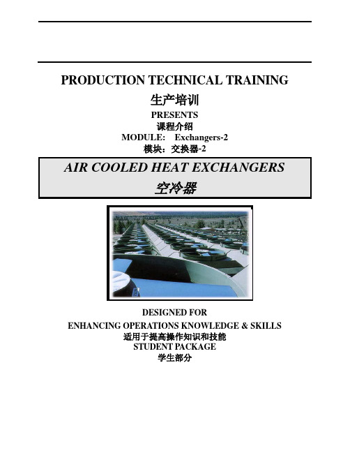
PRODUCTION TECHNICAL TRAINING生产培训PRESENTS课程介绍MODULE: Exchangers-2模块:交换器-2AIR COOLED HEAT EXCHANGERS空冷器DESIGNED FORENHANCING OPERATIONS KNOWLEDGE & SKILLS适用于提高操作知识和技能STUDENT PACKAGE学生部分TABLE OF CONTENTS目录If viewing this TOC on a computer, you can move directly to a subject area by pointing at a title with your cursor and single clicking.如果是在计算机上阅读此TOC,你可以将将光标直接指向标题单击。
INTRODUCTION (1)简介 (1)DEFINITIONS (1)定义 (1)H EAT E XCHANGER (1)热交换器 (1)A IR C OOLED H EAT E XCHANGER (1)空冷器 (1)A IR P LENUM (2)空气调压室 (2)H EADER (2)集气总管 (2)THEORY OF OPERATION (2)操作原理 (2)T EMPERATURE D IFFERENTIAL (2)温差 (2)H EAT T RANSFER (3)传热 (3)TYPES OF AIR COOLED HEAT EXCHANGERS (3)空冷器的型号 (3)F ORCED D RAFT 强迫通风式 (5)I NDUCED D RAFT 诱导通风式 (6)ACHX COMPONENTS (7)T UBE B UNDLE (7)管束 (7)Headers (9)集气总管 (9)Fin Tubes (11)翅管 (11)Fin Characteristics (12)翅片的特征 (12)Tube Attachment and Support (16)散热管附件和支撑物 (16)T HE S TRUCTURE (17)框架 (17)Plenum (17)空气调压室 (17)Mechanical Equipment Support (18)机械设备支撑物 (18)Columns, Braces, and Supporting Steel (18)支柱,支架和支撑钢 (18)Walkways (19)通道 (19)M ECHANICAL E QUIPMENT (19)机械设备 (19)Fans (20)风机 (20)Drivers (24)驱动器 (24)Speed Reducers (25)减速器 (25)P ROTECTIVE D EVICES (28)Vibration Switches (28)振动开关 (28)Temperature Switches (28)温度开关 (28)Overpressure Protection (28)过压保护 (28)C ONTROLS (29)控制器 (29)Local/Manual Controls (29)局部/手动控制器 (29)Automatic Controls (29)自动控制器 (29)OPERATION (29)运作 (29)N ORMAL O PERATION (29)正常运作 (29)S HUTDOWN (30)关闭 (30)S TARTUP (30)启动 (30)OPTIMIZING OPERATION/ENERGY CONSERVATION (30)优化操作/能源节约 (30)V ARYING A IR F LOW (31)改变气流 (31)E XTREME C ASE C ONTROLS (32)极端情况下的控制 (32)Controlling Air Flow (33)控制气流 (33)Moderating Air Temperature (33)Auxiliary Heating Coils (33)A IR C OOLER E FFICIENCY (33)空气冷却器的功效 (33)Blade Angle (35)叶片角度 (35)Belt Slippage (35)皮带打滑度 (35)E XCHANGER A NALYSIS T ABLE (37)MAINTENANCE (38)P REVENTIVE M AINTENANCE (38)预防性维护 (38)P REPARATION F OR M AINTENANCE/I NSPECTION (39)维护和检查的准备工作 (39)Lubrication (39)添加润滑油 (39)TECHNICIAN DUTIES (40)技术员的职责 (40)T AKING E XCHANGERS O UT OF S ERVICE (40)停车检修 (40)A SSEMBLING AND T ESTING E XCHANGERS (42)交换器的安装和测试 (42)P UTTING E XCHANGERS IN S ERVICE (43)投入运行 (43)REFERENCE (44)参考文献 (44)TROUBLESHOOTING (45)故障检修 (45)INTRODUCTION简介This learning module is a description of air cooled heat exchangers and how they are used. It describes the design and operation of this type heat exchanger and discusses the similarities and differences in the types of air cooled heat exchangers. The module is designed to provide personnel with the knowledge to identify the equipment, understand its use, and supervise its usage. If more in-depth information is required, please refer to the referenced information on page 0 of this module.本学习模块描述了空冷器,并对其如何使用进行了说明。
7500冷机操作手册英文
7500冷机操作手册英文Cold machine operation involves several critical steps to ensure safe and efficient functioning. Firstly, it is essential to conduct a thorough inspection of the equipment, checking for any visible signs of damage, wear, or leakage. This initial assessment helps identify potential issues that could compromise the operation or pose safety risks. Once the inspection is complete and no concerns are found, the next step is to prepare the machine for startup.The preparation phase includes verifying the proper levels of coolant, lubricants, and any other necessary fluids. It is crucial to follow the manufacturer's specifications and guidelines to ensure the correct types and quantities of fluids are used. Neglecting this step could lead to equipment malfunction or premature wear. Additionally, all connections, hoses, and fittings should be checked for tightness and secured properly to prevent leaks.With the machine ready, the startup sequence can begin. This typically involves engaging the power supply and initiating the cooling process. Depending on the specific equipment, this may involve activating compressors, pumps, or other components responsible for circulating the coolant. It is essential to closelymonitor the system during this phase, observing temperature readings, pressure gauges, and other indicators to ensure everything is operating within the prescribed parameters.Once the desired temperature levels are achieved, the machine is ready for operation. However, it is crucial to adhere to all safety protocols and guidelines during this stage. Operators should wear appropriate personal protective equipment (PPE), such as insulated gloves, face shields, and protective clothing, to prevent potential injuries from exposure to extreme temperatures or coolant leaks.During operation, it is imperative to maintain vigilance and monitor the machine's performance continuously. Regular checks of temperature, pressure, and flow rates should be conducted to identify any deviations from normal operating conditions. Additionally, any unusual sounds, vibrations, or visual indicators should be promptly investigated and addressed.Proper maintenance is crucial for ensuring the longevity and reliable performance of the cold machine. This includes routine inspections, cleaning, and replacement of worn or damaged components. Adhering to the manufacturer's recommended maintenance schedule and using genuine replacement parts can help prevent breakdowns and extend the equipment's lifespan.In the event of a malfunction or emergency situation, it is essential to follow established protocols for shutting down the machine safely. This may involve activating emergency stop mechanisms, depressurizing the system, or implementing other measures to mitigate potential risks. Operators should be trained in emergency response procedures and have access to appropriate safety equipment, such as fire extinguishers or spill containment kits.Continuous training and education are vital for ensuring the safe and efficient operation of cold machines. Operators should be knowledgeable about the equipment's functionality, safety protocols, and troubleshooting procedures. Regular refresher training sessions and the dissemination of updated manuals or safety guidelines can help keep operators informed and prepared for any situation.In conclusion, the operation of cold machines requires a comprehensive approach that prioritizes safety, maintenance, and adherence to established protocols. By following proper procedures, conducting regular inspections and maintenance, and staying vigilant during operation, manufacturers and operators can maximize the equipment's performance, minimize downtime, and ensure a safe working environment for all personnel involved.。
ENInstructions - 爱尔斯(Airs)空气调节器说明书

309924LENInstructions - Parts ListAir RegulatorsImportant Safety Instructions.Read all warnings and instructions in this manual.Save these instructions.Part No.Description Inlet Outlets HandleMaximum Inlet Pressure psi (MPa, bar)Maximum CFM Regulated Pressure Range psi (MPa, bar)at 50 psi (.34 MPa, 3.4 bar 234389Air Regulator withgauge, self relieving1/4 in. npt(m)1/4 in. npt(f)knob 160(1.1, 11)22 CFM 0-160(1.1, 11)234434Air Regulator withgauge, self relieving1/4 in. npt(m)1/4 in. npt(f)knob 160(1.1, 11)35 CFM 0-160(1.1, 11)234390Mini Air Regulator withgauge, self relieving1/4 in. npt(f)1/4 in. npt(f)knob 160(1.1, 11)22 CFM 0-160(1.1, 11)24H419Mini Air Regulator withgauge, self relieving1/4 in. BSP(f)3/8 in. BSP(f)knob 150 (1.0, 10)22 CFM 0-150(1.0, 10)24H420Mini Air Regulator withgauge, self relieving 1/4 in. npt(f)3/8 in. npt(f)knob150 (1.0, 10)22 CFM0-150(1.0, 10)at 100 psi (0.7 MPa, 7 bar 234391Air Regulator with2 regulated outlets, 1 unregulated outlet3/8 in. npt(f)1/4 in. npt(f)tee 175(1.2, 12)50 CFM 0-175(1.2, 12)234392Air Regulator with3 regulated outlets3/8 in. npt(f)1/4 in. npt(f)tee 175(1.2, 12)50 CFM 0-175(1.2, 12)234393Air Regulator 234391with gauge and shutoff valve, 1 regulated outlet, 1 unregulated outlet3/8 in. npt(m)1/4 in. npt(f)tee160(1.1, 11)50 CFM0-160(1.1, 11)234394Air Regulator 234392with gauge and shutoff valve, 2 regulated out-lets3/8 in.npt(m)1/4 in. npt(f)tee 160(1.1, 11)50 CFM 0-160(1.1, 11)Installation2309924LInstallationBefore installing air line components, blow out the pipe line to remove debris. Be sure air to the regulator is clean. Erratic operation or loss of regulation is usually caused by dirt in the regulator.Use pipe compound or tape sparingly and only on male threads. Locate the regulator as close as possible to the equipment it serves.Install a main air shutoff valve upstream from the air controls to isolate them for service.Shop Air Piping LayoutNOTE: •Main Air Line stand pipe should not be smaller than compressor outlet size.•A minimum of 25 ft (7.62 m) from compressor to first filter outlet is required to cool air [50 ft. (15.24 m) optimum].Membrane or desiccant air drying systemDrain valveBall valveS l o pe w n an d a w a y .R e c o mm e n d e d 4 i n . (117 m m ) dr o p i n50 f t (15.24 m ) g a lv a n i z e d pi p e .1/2 in.(13 mm)dropsAir control unit or air filterDrain legAir filterCoalescerMain airshutoff valveCompressorFlexible hosebetween compressor and stand pipeMain air line3/4 in. (19 mm) minimum 1-1/4 in. (32 mm) optimum15-20 f t (4,6-6,1 m )Installation309924L 3Minimum Pipe Size RecommendationsCompressorMain Air LineHP CFM Length ft (m)Size in. (mm)1-1/2 - 2 6 - 9any 3/4 (19)3 - 512 - 20Up to 200 (61)3/4 (19)Over 200 (61) 1 (25.4)5 - 1020 - 40Up to 100 (30.5)3/4 (19)Over100-200 (30.5-61)1 (25.4)Over 200 (61)1-1/4 (31.8)10 - 1540 - 60Up to 100 (30.5)3/4 (19)Over100-200 (30.5-61)1-1/4 (31.8)Over 200 (61)1-1/2 (38.1)Air Pressure Drop Through Hose, by Hose Length and IDTemperature = 68° FInlet Pressure4 ft (1.22 m)10 ft (3.05 m)15 ft (4.6 m)20 ft (6.1 m)25 ft (7.62 m)50 ft (15.24 m)Air Hose ID 1/4 in. (6.4 mm)psi (kPa, bar)SCFM (ft 3/min)40 (276, 2.8) 6 (41, .4)148 (55, .6)109.5 (66, .7)911 (76, .8)812.75 (88, 0.9)824 (165, 1.7)850 (345, 3.4)7.5 (52, .5)1710 (69, .7)1212 (83, .8)1114 (97, 1)1016 (110, 1.1)928 (193, 1.9)960 (414, 4.1)9 (62, .6)2012.5 (86, .9)1414.5 (100, .1)1216.75 (115,1.2)1119 (131, 1.3)1131 (214, 2.1)1070 (483, 4.8)10.75 (74, .7)2214.5 (100, 1)1617 (117, 1.2)1419.5 (134, 1.3)1322.5 (155, 1.6)1234 (234, 2.3)1180 (552, 5.5)12.25 (84, .8)2516.5 (114,1.1)1819.5 (134, 1.3)1622.5 (155, 1.6)1525.5 (176, 1.8)1437 (255, 2.6)1290 (621, 6.2)14 (97, 1)2818.75 (129, 1.3)2022 (152, 1.5)1725.25 (172, 1.7)1629 (200, 2)1539.5 (169, 2.7)12Air Hose ID 5/16 in. (7.9 mm)psi (kPa, bar)SCFM (ft 3/min)40 (276, 2.8) 2.25 (16, .2)15 2.75 (19, .2)10 3.25 (22, .2)9 3.5 (24, .2)84 (28, .3)88.5 (59, .6)850 (345, 3.4) 3 (21, .2)193.5 (24, .2)12 4 (28, .3)11 4.5 (31, .3)10 5 (34, .3)910 (69, .7)960 (414, 4.1)3.75 (26, .3)22 4.5 (31, .3)155 (34, .3)13 5.5 (38, .4)116 (41, .4)1111.5 (79, .8)1070 (483, 4.8) 4.5(31, .3)26 5.25 (36, .4)176 (41, .4)15 6.75 (47, .5)137.25 (50, .5)1213 (90, .9)1280 (552, 5.5) 5.5 (38, .4)30 6.25 (43, .4)197 (48, .5)178 (55, .6)158.75 (60, .6)1414.5 (100, 1)1390 (621, 6.2)6.5 (45, .4)347.5 (52, .5)228.5 (59, .6)199.5 (66, .7)1710.5 (72, .7)1616 (110, 1.1)14Repair4309924LPressure AdjustmentTurn clockwise to increase air pressure. Turn counter-clockwise to decrease air pressure.NOTE: Push in the knob of Part No. 234389, 234390, 24H419, and 24H420 air regulators to lock their pres-sure setting.Pressure Relief ProcedureThe following is a basic pressure relief procedure. Be sure to follow the specific pressure relief procedure in your spray gun and/or fluid supply equipment manuals.1.Close the main air shutoff valve.2.Trigger the gun or dispense valve and open anydrain valves to relieve pressure.Repair1.Follow Pressure Relief Procedure , above.2.Disassemble the regulator. Refer to Parts drawings.3.Wash parts with household soap and water or dena-tured alcohol.4.Wipe parts dry with a clean, soft, dry rag. Use com-pressed air to blow dirt and contaminants out of the regulator body.5.Inspect parts for wear or damage. Replace dam-aged parts.6.Reassemble the regulator.To avoid injury, relieve air and fluid pressure beforeParts309924L 5PartsPart No. 234389 and 234434NOTE: 234389 comes with a pressure relief valve.Parts6309924LPart No. 234393 (1 regulated, 1 unregulated outlet)and 234394 (2 regulated outlets)Part No. 234391 (2 regulated, 1 unregulated outlet)and 234392 (3 regulated outlets)234391 for 234393or119285234392 for 234394289165289159289160289151289157289156289158288780289154288779289153289150for 234391/234393289166for 234392/234394289155289152or*Repair Kit 289167 available for models 234391 & 234392.OutletInletOutletOutletParts 309924L7All written and visual data contained in this document reflects the latest product information available at the time of publication.Graco reserves the right to make changes at any time without notice.Original instructions. This manual contains English. MM 309924Graco Headquarters: MinneapolisInternational Offices: Belgium, China, Japan, Korea GRACO INC. P.O. BOX 1441 MINNEAPOLIS, MN 55440-1441Copyright 2003, Graco Inc. is registered to ISO 9001Revision L, March 2018Graco Standard WarrantyGraco warrants all equipment referenced in this document which is manufactured by Graco and bearing its name to be free from defects in material and workmanship on the date of sale to the original purchaser for use. With the exception of any special, extended, or limited warranty published by Graco, Graco will, for a period of twelve months from the date of sale, repair or replace any part of the equipment determined by Graco to be defective. This warranty applies only when the equipment is installed, operated and maintained in accordance with Graco’s written recommendations.This warranty does not cover, and Graco shall not be liable for general wear and tear, or any malfunction, damage or wear caused by faulty installation, misapplication, abrasion, corrosion, inadequate or improper maintenance, negligence, accident, tampering, or substitution ofnon-Graco component parts. Nor shall Graco be liable for malfunction, damage or wear caused by the incompatibility of Graco equipment with structures, accessories, equipment or materials not supplied by Graco, or the improper design, manufacture, installation, operation or maintenance of structures, accessories, equipment or materials not supplied by Graco.This warranty is conditioned upon the prepaid return of the equipment claimed to be defective to an authorized Graco distributor for verification of the claimed defect. If the claimed defect is verified, Graco will repair or replace free of charge any defective parts. The equipment will be returned to the original purchaser transportation prepaid. If inspection of the equipment does not disclose any defect in material or workmanship, repairs will be made at a reasonable charge, which charges may include the costs of parts, labor, and transportation.THIS WARRANTY IS EXCLUSIVE, AND IS IN LIEU OF ANY OTHER WARRANTIES, EXPRESS OR IMPLIED, INCLUDING BUT NOT LIMITED TO WARRANTY OF MERCHANTABILITY OR WARRANTY OF FITNESS FOR A PARTICULAR PURPOSE .Graco’s sole obligation and buyer’s sole remedy for any breach of warranty shall be as set forth above. The buyer agrees that no other remedy (including, but not limited to, incidental or consequential damages for lost profits, lost sales, injury to person or property, or any other incidental or consequential loss) shall be available. Any action for breach of warranty must be brought within two (2) years of the date of sale.GRACO MAKES NO WARRANTY, AND DISCLAIMS ALL IMPLIED WARRANTIES OF MERCHANTABILITY AND FITNESS FOR A PARTICULAR PURPOSE, IN CONNECTION WITH ACCESSORIES, EQUIPMENT, MATERIALS OR COMPONENTS SOLD BUT NOTMANUFACTURED BY GRACO . These items sold, but not manufactured by Graco (such as electric motors, switches, hose, etc.), are subject to the warranty, if any, of their manufacturer. Graco will provide purchaser with reasonable assistance in making any claim for breach of these warranties.In no event will Graco be liable for indirect, incidental, special or consequential damages resulting from Graco supplying equipment hereunder, or the furnishing, performance, or use of any products or other goods sold hereto, whether due to a breach of contract, breach of warranty, the negligence of Graco, or otherwise.FOR GRACO CANADA CUSTOMERSThe Parties acknowledge that they have required that the present document, as well as all documents, notices and legal proceedings entered into, given or instituted pursuant hereto or relating directly or indirectly hereto, be drawn up in English. Les parties reconnaissent avoir convenu que la rédaction du présente document sera en Anglais, ainsi que tous documents, avis et procédures judiciaires exécutés, donnés ou intentés, à la suite de ou en rapport, directement ou indirectement, avec les procédures concernées.Graco InformationFor the latest information about Graco products, visit .For patent information, see /patents .TO PLACE AN ORDER, contact your Graco distributor or call to identify the nearest distributor.Phone: 612-623-6921 or Toll Free: 1-800-328-0211 Fax: 612-378-3505。
CMA Flodyne Hydradyne ELD Series 移动应用型空气冷化油冷器说明说明书
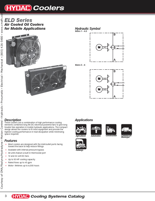
ApplicationsMunicipalDescriptionThese coolers use a combination of high performance coolingelements combined long life DC electrical powered fans to give long trouble free operation in mobile hydraulic applications. The compact design allows the coolers to fit most equipment and provide the highest cooling performance in heat dissipation while minimizing space required.FeaturesM ost coolers are designed with the inlet/outlet ports facing UÊtoward the back to help reduce fittings Available with internal pressure bypass UÊAll units feature a built in thermostat port UÊ12 and 24 volt DC fans UÊUp to 50 HP cooling capacity UÊRated flows up to 45 gpm UÊMotor lifetimes up to 8,000 hoursUÊHydraulic SymbolSizes 1 - 4.5Sizes 5 - 6Air Cooled Oil Coolersfor Mobile Applicationse s y of C M A /F l o d y n e /H y d r a d y n e ŀ M o t i o n C o n t r o l ŀ H y d r a u l i c ŀ P n e u m a t i c ŀ E l e c t r i c a l ŀ M e c h a n i c a l ŀ (800) 426-5480 ŀ w w w .c m a fELD 1H 3.5 12 S F XModel ELD = Air Cooled Oil Cooler with DC Motor DriveSize 1H 1.5H 2H 3H 4H 4.5H 5H 6H(see heat dissapation table on page 5)Modification Number (latest version always supplied)Motor Drive Voltage 12 = 12 volt DC 24 = 24 volt DCAir Flow Direction S = Suction (standard)B = Blowing(consult factory)AccessoriesTS 140 = 140°F set point (Additional set points available - consult factory) F = Optional Foot Mount IBP = Inegrated bypass valve Opening Pressure Drop (IBP Only) 2 = 2 bar (29 psi) 3 = 3 bar (45 psi)e s y of C M A /F l o d y n e /H y d r a d y n e ŀ M o t i o n C o n t r o l ŀ H y d r a u l i c ŀ P n e u m a t i c ŀ E l e c t r i c a l ŀ M e c h a n i c a l ŀ (800) 426-5480 ŀ w w w .c m a fPressure Drop* P ressure Drop Curves above using fluid with a viscosity of 30 mm2/s. For other viscosities the result must be multiplied by the K Factors below.Heat Dissapation05101520253035404550Tolerance: +/- 5%05101520253035404550556065Oil flow [GPM]ELD 6ELD 5ELD 4ELD 3ELD 2ELD 1ELD 1.5ELD 4.50.05.010.015.020.025.030.035.040.045.050.055.060.0020406080Oil flow (GPM)P r e s s u r e D r o p @ 30 m m /s (P S I )ELD 4ELD 2ELD 1ELD 1.5ELD 1: +/- 5%*Values measured at T = 72°F , may vary at lower dT valuesELD 6ELD 3ELD 5ELD 4.5s y o f C M A /F l o d y n e /H y d r a d y n e ŀ M o t i o n C o n t r o l ŀ H y d r a u l i c ŀ P n e u m a t i c ŀ E l e c t r i c a l ŀ M e c h a n i c a l ŀ (800) 426-5480 ŀ w w w .c m a fConstructionHousing Welded Steel Heat Exchanger Aluminum FanPlastic Maximum Viscosity 2000 cst.Maximum Oil Temperature 266°F Maximum Operating Pressure 230 psi Mounting Position All positions Fan Rotation See arrow on fanFluidsMineral Oil to Din 51524 Part 1 and 2AccessoriesFoot Bracket - ELD 2-6 & ELH 2-51.97"2.15" 0.71" 18mm4mme s y of C M A /F l o d y n e /H y d r a d y n e ŀ M o t i o n C o n t r o l ŀ H y d r a u l i c ŀ P n e u m a t i c ŀ E l e c t r i c a l ŀ M e c h a n i c a l ŀ (800) 426-5480 ŀ w w w .c m a fDimensionsSize 1.5Z1Oil Port e s y o f C M A /F l o d y n e /H y d r a d y n e ŀ M o t i o n C o n t r o l ŀ H y d r a u l i c ŀ P n e u m a t i c ŀ E l e c t r i c a l ŀ M e c h a n i c a l ŀ (800) 426-5480 ŀ w w w .c m a fDimensions Sizes 5 - 6e s y of C M A /F l o d y n e /H y d r a d y n e ŀ M o t i o n C o n t r o l ŀ H y d r a u l i c ŀ P n e u m a t i c ŀ E l e c t r i c a l ŀ M e c h a n i c a l ŀ (800) 426-5480 ŀ w w w .c m a f。
Air Conditioner 用户手册说明书

HSC -12L/HSC(O)-14HSC(O)-18/HSC(O)-24AMODEL:USER'S MANUALAIR CONDITIONERHSC-12L HSC-14/18/24A HSCO-14/18/24ANOZZLE TYPELOUVER TYPE■ SAFETY INSTRUCTIONS ■ GENERAL ADVICE BEFORE USE ■ EXTERIOR DESCRIPTION ■ SPECIFICATIONS■ CONTROL PANEL FUNCTIONS ■ MODE CHANGING METHOD ■ HOW TO SET THE 'OFF'TIMER ■ TEMPERATURE CONTROL OPERATION ■ SELECTION OF LOCK OR UNLOCK ■ 'ERROR'and WARNING INDICATORS ■ FIREALARM&ERROR SIGNAL CONNECTION ■ TROUBLE SHOOTING ■ MAINTENANCE ■ ACCESSORY ■ WARRANTYTABLE OF CONTENTS345~678~91011121314~1516171819203rev0SAFETY INSTRUCTIONSThe following instructions are to ensure user’s safety and to prevent any physical injury or material damage. Please read carefully and follow all instructions.There are two sections to these instructions: WARNING and CAUTION.The following symbols are for your guidance:= You must NOT .= You MUST .Keep this manual in a visible location near the Heat pump for easy reference.SAFETY INSTRUCTIONSGENERAL ADVICE BEFORE USE* You have to connect supply cord at least standardIf the supply cable is damaged, it must be replaced by the manufacturer,its service agent or similarly qualified person in order to avoid a hazard.· Ensure the safety of the location in which Air conditioner is to be used.· Ensure the floor or ground is smooth and sound.· Ensure you allow at least 20" (50cm) air space all around the AIR CONDITIONER.· When in position LOCK the casters to prevent rolling.FOR MAXIMUM EFFICIENCY· Exhaust ducting should be no longer than maximum efficiency.· Ensure correct electricity supply.5rev0※ HSC-12LPOWER PLUGELECTRIC PANEL(ACCESS BY AUTHORISED SERVICE PERSONNEL ONLY)CONDENSER OUTLET (HOT AIR)CONDENSER FILTEREXTERIOR DESCRIPTIONFRONT VIEWBACK&SIDE VIEWFRONT VIEWBACK&SIDE VIEW① Cool Air Ooulet② Handle③ Digital Controller④ Electrical Access panel⑤ Power Plug⑥ Fire Alarm Connection Port⑦ Casters (Front Lockable)※ HSC(O)-14 & HSC(O)-18 & HSC(O)-24A7rev0SPECIFICATIONSCONTROL PANEL FUNCTIONS※ HSC-12Lcooler to run for. You can set 0~24 hours. Time intervals are30mins. up to 10 hours and then 1 hour between 10 and 24 hours.⑥ Room : If the LED is On, the displayed temperature is for Room temp.If the LED is Off, the displayed temperature is for spot temp.⑦ Comp. : When the compressor is operating, the LED is On.⑧ Error : Error signal( E2 : Low Pressure, E3 : Sensor, E5 : BLDC Motor, AF: Eva Freezing)⑨ Check : If Water full or Align Drain Tank is checking. The LED is on.⑩ Display : Display Room/Spot temperature, the setting temp and off timein case of setting them.(Display of 'LO' : under the 32℉, Display of 'HI' : over the 99℉)9rev0CONTROL PANEL FUNCTIONS① Power : Use to power on / off.② ∨ ∧ Button : Raises or lowers temperature and/ or sleep (off) time.③ Mode : Use to select cooling mode or Dehumidifier mode or FAN mode ④ Low Mode : Controls fan low speed.⑤ High Mode : Cantrol fan high speed.⑥ Off Timer : To set the length of time, once turned on, that you wish the cooler to run for. You can set 0~24 hours. Time intervals are 30mins.up to 10 hours and then 1 hour between 10 and 24 hours.⑦ Room : If the LED is on, the displayed temperature is for room temp.⑧ Comp. : When the compressor is operating. the LED is on.⑨ Error : Error signal (E1:High pressure,E2:Low pressure,E3:Sensor problem,rP:Reverse phase)⑩ Check : If water full or Aligh Drain Tank is checking. The LED is on.⑪ Display : Display Room temperature, and also the setting temp and sleep time if they had been set. (Display of 'LO' : under the 32˚F, Display of 'HI' : over the 99˚F)※ HSC(O)-14 & HSC(O)-18 & HSC(O)-24AMODE CHANGING METHODCO OLHU FA COOLING MODEIf you press 'cool' button. 'COOL' is displayed. then LED is on.DEHUMIDIFIER MODEWhen the cooling is operating, If you pressthe 'cool' button. 'dEHU' is displayed.then LED is on.FAN MODEWhen the Dehumidifier is operating. If you press the 'cool' button, 'FAn' is displayed.then LED is off.11rev0HOW TO SET THE ‘OFF’ TIMER.73AIR CONDITIONER is operating, press theOff Timer ' button and set the length of time you want by ∧ or ∨. Each time you press the button 'time to off ' period by 30mins. 'Off Timer ' lamp will be on which indicatesAIR CONDITIONER is in sleep (Off Timer) mode.'Off Timer ' button during its 4. To CANCEL timing, press and hold 'Off Timer ' button for ONE second. It will then switch the timer off automatically.TEMPERATURE CONTROL OPERATION ※ HSC-12L791. When turn ON, the setting temperature is displayed.SELECTION OF LOCK OR UNLOCKSELECTION OF ℉ OR ℃7979.2. You can set 'UNLOCK' or 'LOCK' after pressing'∧' button.UL2679button simultaneously for three seconds.13 rev0‘ERROR’and WARNING INDICATORSThe machine’s safety devices will automatically signal any problems via the display window on the control panel. The information below shows how to read these signals.‘ERROR’and WARNING INDICATORS※ HSC(O)-14 & HSC(O)-18 & HSC(O)-24Ae2e3alrev015Fire Alarm & Error Signal ConnectionConnecting Error Signal with warning device1. Remove 'Cap' and the 'Fire Alarm cover'.2. Use recommended error signal wire size from 16 AWG to 26AWG for a solid wire, or 16 AWG to 22 AWG for a stranded FIRE ALARM SIGNAL CONNECTION17rev0TROUBLE SHOOTINGMAINTENANCE※ HSC-12L※ HSC(O)-14 & HSC(O)-18 & HSC(O)-24A1. To remove EVA filters, open the front grille ① and pull the filter inside ②.2. To remove COND filters, slide up a little ① and pull towards you ②.3. Clean the filters with water or compressed air.4. Clean evaporator and condenser units with a vacuum cleaner or compressed air.1. After cleaning, completely dry the inside of the unit by operating on 'Fan Mode ' for 3 to 4 hours.2. Turn "OFF " at control panel, remove plug from socket. Coil and store cable neatly.3. Keep machine suitably covered to prevent damage by damp, humidity and dust.CLEANING THE AIR FILTERSMAINTENANCE1. To remove filters, slide up a little ① and pull towards you ②.2. Clean the filters with water or compressed air.3. Clean evaporator and condenser units with a vacuum cleaner or compressed air.CLEANING THE AIR FILTERSMAINTENANCE19rev0ACCESSORY。
CRENT 空调维护指南说明书

For units equipped with dry-bulb enthalpy sensors, accessory HH57AC078 can be used to reconfigure the economizer for outdoor enthalpy changeover control.
SIZES 036-303 072-336 036-336 036-060 036-060 036-303 072-336 036-336 036-060 036-060 036-120 072-243 036-060
SMC Thermo-con 机械空冷熔炉安装与维护手册说明书
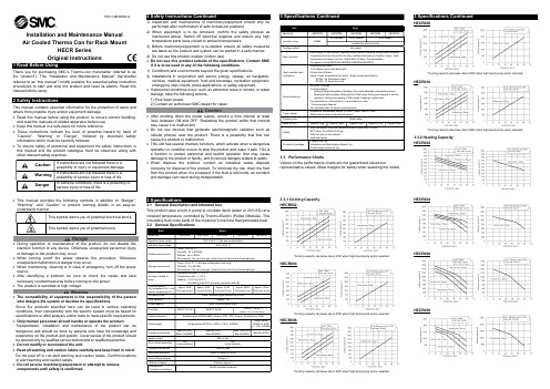
Installation and Maintenance Manual Air Cooled Thermo Con for Rack MountHECR Series Original InstructionsThank you for purchasing SMC’s Thermo-con (hereinafter referred toas the “product”). This “Installationand Maintenance Manual” (hereinafter referred to as “this manual”) briefly explains the essential safety instruction procedures to startandstoptheproductandresetits alarms. Readthismanual before using.This manual contains essential information for the protection of users and others from possible injury and/or equipment damage.Read this manual before using the product, to ensure correct handling,and read the manuals of related apparatus before use. Keep this manual in a safe place for future reference.These instructions indicate the level of potential hazard by label of “Caution”, “Warning” or “Danger”, followed by important safety information which must be carefully followed.To ensure safety of personnel and equipment the safety instructions in this manual and the product catalogue must be observed, along with other relevant safety practices.This manual provides the following symbols in addition to “Danger”, “Warning”, and “Caution” to present warning details in an easy-to-understand manner.During operation or maintenance of the product, do not disable the interlock function of any device. Otherwise unexpected personnel injury or damage to the product may occur.When turning on/off the power observe the procedure. Otherwise unexpected malfunction or danger may occur.When maintaining, cleaning or in case of emergency, turn off the power source.After identifying a problem be sure to check the cause and take necessary countermeasures before turning on the power. The product is operated at high voltage.The compatibility of equipment is the responsibility of the person who designs the system or decides its specifications.Since the products specified here can be used in various operating conditions, their compatibility with the specific system must be based on specifications or after analysis and/or tests to meet specific requirements. Only trained personnel should handle or operate the product.Transportation, installation and maintenance of the product can be dangerous and should be done by persons who have full knowledge and experience on the product and system. Cover panels of the product should be opened only by qualified service technicians or qualified personnel. Do not modify or reconstruct the unit.Read all warning and caution labels carefully and keep them in mind. Do not peel off or rub alert warning and caution labels. Confirm locations of alert warning and caution labels.Do not service machinery/equipment or attempt to remove components until safety is confirmed.After shutting down the power supply, ensure a time interval at least *Cooling capacity decrease about 20W when high head pump option selected.HECR004*Cooling capacity decrease about 50W when high head pump option selected.HECR006*Cooling capacity decrease about 50W when high head pump option selected.3 Specifications ContinuedHECR008*Cooling capacity decrease about 50W when high head pump option selected.HECR010*Cooling capacity decrease about 50W when high head pump option selected.3.3.2 Heating Capacity HECR002HECR004HECR006HECR008HEC-OM-R008-GHECR0103.3.3 Pump CapacityHECR002HECR004HECR006HECR008 / HECR010RTD wiring4 Special Features ContinuedFan speed control (HECR004,HECR006,HECR008,HECR010)Fan speed is controlled automatically in accordance with the heat load.5 Installation5.1 InstallationPay special attention to the safety of all personnel when installing andtransporting the product.Do not install the product unless the safety instructions have been readand understood.The product is heavy, be careful when installing or moving the product.Always transport the product using both handles.Leakage from the product may damage peripheral equipment. Install adrain pan under the product to capture leakage. Furthermore, mountdevices like a leak sensor on the installed drain pan to detect leakage sothat it can alert operators around the area.Install the product above 0.6m from the floor.5.2 EnvironmentDo not use in an environment where the product is directly exposed towater, oil, corrosive gases, chemicals, salt water or steam.The product should be installed upright on a stable base.Do not install the product in a location where the air inlet and air outletvents are blocked. Also do not use the product in a sealed enclosure.Do not use in an explosive atmosphere.Do not mount the product in a location where it can be exposed toprolonged sunlight. Use a protective cover.Do not mount the product in a location where it is subject to strongvibrations and/or shock. Check the product specifications.Do not use the product where it can be exposed to strong electrical ormagnetic emissions.Do not mount the product in a location where it is exposed to noisesources (such as discharging equipment, large relay and thyristor).Do not mount the product in a location with an altitude of more than1000 meters.Do not mount the product where it is exposed to materials such assilicone, which may generate harmful gas.Install the product in a location where the ambient temperature range isbetween 10 to 35°C and the relative humidity range is between 35 to80%. No dew condensation is allowed on the unit.Do not mount the product in a location exposed to radiant heat.5.3 MountingWhen mounting the product to a cabinet, use a design which shall holdthe weight at the bottom. Ensure safety with transportation test if theproduct is to be installed on a transportation device such as a trailer.Mount the product using the fixing holes in the front of the product. UseM5,M6 screws (bolts) or equivalent to the fix the product.Be sure to correctly tighten all screws to the required torque.(M5:3.0Nm, M6:5.2Nm)5.4 PipingEnsure that the power source and the power supply of the product isturned off (or the power plug must come off )Ensure the flow rate of the circulating fluid is as high as possible tomaintain the temperature stability. Therefore, the length of the externalpiping should be minimized and internal diameter should be as large aspossible. Piping must have sufficient strength for the maximumdischarge pressure of the circulating circuit.Likewise, if a tube is bent or multiple elbow fittings are used, the pipingresistance will increase and the flow rate will decrease. If the flow ratefalls, the temperature stability will decrease.If installing a tank externally, only a sealed tank should be used. Do notuse an open tank.Normal When high head pump option selectedNormal When high head pump option selectedNormal When high head pump option selectedNormal When high head pump option selectedEnsure that the INLET and OUTLET for circulating fluid is connected correctly. If any valves are used ensure that they do not restrict the flow, otherwise low flow may cause an alarm.When installing piping or fittings, ensure sealant material does not enter inside the port. When using seal tape, leave 1.5 to 2 threads exposed on the end of the pipe/fitting.Be sure to correctly tighten the fitting fittings to the required torque(Rc1/4:12 to 14 N ・m, Rc3/8:15 to 20N ・m). 5.5 WiringEnsure that the power source and the power supply of the product is turned off before connecting the various connectors and power supply cable.Supply disconnecting device according to IEC60974-1 and IEC60947-3 for the product must be provided in the end system.Do not install the disconnecting device in the place where the operation is difficult. And also the switch of the disconnecting device must comply with the direction of the switch specified by IEC60447. Preparation and wiring of power supply cable 1) Strip the sheath from both ends of the cable.2) Disassemble the power supply connector. Crimp one end of the cable to L, N, E inside of the connector, then reassemble the power supply connector.3) Connect the other end of the cable to a plug or terminals (e.g. crimped terminal).Ensure that there is enough space between the power supply cable and the communication cable of the product and power cables of other equipment.Ensure the power supply and ground connections are made correctly. Be sure to provide the grounding. The PE line of the power supply cable is available for grounding. Do not connect the ground in common with the ones for equipment that generates strong electromagnetic noise or high frequency.When an external temperature sensor is connected, connect the sensor with a shield cable. Use a platinum resistant temperature sensor (Pt100ohm, 3-wiring type, class A, 1mA).Connect the host to this unit with a twisted pair shield cable when applying communication function or external sensor and alarm output function.When using the Communication connector and Signal/External temperature sensor, connect the circuit separated from the mains circuit by reinforced insulation.Ensure that external instruments connecting to this product provide the enclosure complied with UL61010-1 and use the cable which provide flame resistance (over VW-1). 5.6 Filling the product1. Ensure that the power source and the power supply of the product is turned off (or the power plug must come off).2. Remove the reservoir cap.(When setting the product again, confirm the level of fluid does not exceed the “H ” mark)3. If using Ethylene Glycol, refer to the suppliers Material Safety Data Sheet (MSDS) and wear Personal Protective Equipment (PPE) as appropriate.4. Fill the circulating fluid into the reservoir. Stop filling once the level of fluid reaches the “H” mark.5. Turn on the power switch to fill the piping with the fluid.6. When the piping is filled with the circulating fluid, the level of the reservoir decreases and low fluid level alarm (ERR20) arises accordingly. Then, turn off the power supply once again.7. Repeat the step from 4 to 6 until ERR20 alarm doesn’t appear anymore. 8. Then, replace the cap on the reservoir and tighten it securely. 9. Keep the fluid level between H and L of the level indicator.Never touch the power switch with wet hands to avoid electrical shock.Do not touch the surface when the set temperature is high. Temperature of the tank and the chassis near the tank could be high.Fluid other than water or Ethylene Glycol (up to 20%) should not be used as circulating fluid. Using such fluid may lead to leakage or damage of the pump.Operation of the pump with a large amount of air left in the piping for prolonged period may damage the pump. Remove air from piping before starting operation.If the power switch is turned on without circulating fluid, the pump could be damaged.Take care not to spill water over the product when supplying water to the reservoir. When a spill is made, wipe it off immediately and only supply power after it has dried. If this procedure is neglected, it may cause damage to the product.If a fluid with low conductivity such as DI water is used as circulating fluid, it can cause static electricity due to friction and damage the product. Take measures to minimize the static electricity from circulating fluid. If the product is operating for a long time with large temperature fluctuations after reaching the set temperature, the product may be damaged. Please set the PID values by using the auto-tuning function.6 Operation6.1 Power UpWhen power is turned on, the software version is indicated on display panel for approx. 1 second. 6.2 OperationThe product begins operation immediately after the power is turned on. The pump and heat exchanger will be running and the product will begin temperature control.6.3 SettingsThree different levels of settings are available depending on the content, which needs to be set. Level 1: Used in normal operation e.g. settingof target temperature and offset.Level 2: Used at maintenance and initial settingfor setting of controller/PID.Level 3: Used at initial setting for thecommunication function.The key functions are as follows:[SEL]: Used to show the item that needs to bechanged in selected mode level. [▽△]: Used to change the value of the item selected. [RET]: Used to fix the value changed by [▽△] key.Press again to return to current temperature indication.[AT]: Used to start auto tuning in auto tuning mode(This function works when the control operation mode is 2 in level setting 1)When pressed during auto tuning, the auto tuning is stopped.When no input is made within 1 minute regardless of setting mode, the display returns to the current temperature indication.The data input is written to FRAM and memorized after the power supply is turned off.To return all of the setting values to default: Turn on the power supply while pressing [SEL] and [RET] keys.6.3.1 Level 1-Settings6.3.3 Level 3-SettingsHECR002HECR002-A5-E(option)HECR004HECR004-A5-E(option)Displays the measured temperature.#1 and #2 change when [ ] or [ ] is N E (Earth) LCrimped terminal L E N PlugCable quantity and size; 3 cores, 14AWG(include earth) 100℃, 300V, VW-1 or moreHECR006HECR006-A5-E(option) HECR008HECR008-A5-E(option) HECR010HECR010-A2-E(option)8 Key PartsHECR002 / HECR004 / HECR006HECR008 / HECR0109.1Daily Check1) Indicationofdisplaypanel: Checktemperature conditionandconfirmwhether or not an alarm has occurred.2)Confirm that the heat sink and panel are free from dust. A large amountof dust may impair the performance.3)Confirm there is no leakage of circulating fluid and check the conditionof the piping (e.g. no tight bends or crushed pipes).4) Confirm there is no abnormal sound, smell or heating from the product.When cleaning the panel or heat sink use a vacuum cleaner to removethe dust. Do not use water or steam since it leads to rusting of the frame.9.2 General MaintenanceReplace the circulating fluid regularly to avoid any problems due to algaeor contamination.<Drain circulating fluid>HECR002 / HECR004 / HECR0061. Drain circulating fluid from the Fluid IN.Loosen the reservoir cap to help draining. (Do not remove the cap)2. To drain from the piping, blow air (0.1MPa, about 1 minute) from FluidOUT to Fluid IN. Close the reservoir cap while blowing.HECR008 / HECR0101. Drain circulating fluid from the Drain port.Loosen the reservoir cap to help draining. (Do not remove the cap)2. To drain from the piping, blow air (0.1MPa, about 1 minute) from FluidOUT to Drain port. Close the reservoir cap and Fluid IN while blowing.The repair and maintenance services of this unit are performed only atSMC factory. SMC does not provide on-site repair or maintenanceservice in a national or overseas situation.It is recommended to prepare spare units to minimize downtime due tothose repair and maintenance services.Drain the fluid from the product when it is returned for the repair andmaintenance service. If the fluid is left inside, an accident and damagecan result during transportation.Do not make any modification to the product.Do not disassemble the product, unless required by installationinstructions.If fluid other than water is used, wash the circulating fluid circuit withwater or DI water before returning the product to SMC. Products thathave not been washed may not be accepted at the factory.10 Troubleshooting11 Declaration of ConformityBelow is a sample Declaration of Conformity(DoC) used for this product.An actual DoC will be supplied with each product.4-14-1, Sotokanda, Chiyoda-ku, Tokyo 101-0021 JAPANTel: + 81 3 5207 8249 Fax: +81 3 5298 5362URL https://Note: Specifications are subject to change without prior notice and any obligation on the part of the manufacturer.© 2022 SMC Corporation All Rights Reserved。
Owners Manual Air Conditioner说明书

OWNER’S MANUALAIR CONDITIONER• Please read this manual carefully and thoroughly before using this appliance.• Contact an Authorized Service representative for repair or maintenance of this unit.• Contact an installation technician for the installation of this unit.• This appliance is not intended to be used by young children or disabled persons without supervision.• Young children should be supervised to ensure that they do not play with the air conditioner.TYPE : Multi V Water IV (Heat Pump and Heat Recovery)ARWN080LAS4 / ARWB080LAS4ARWN100LAS4 / ARWB100LAS4ARWN120LAS4 / ARWB120LAS4ARWN140LAS4 /ARWB140LAS4ARWN160LAS4 /ARWB160LAS4ARWN180LAS4 / ARWB180LAS4ARWN200LAS4 / ARWB200LAS4ENGLISH TÜRKÇEDear Customers,We wish that our product, which has been manufactured in modern facilities and tested meticulously for quality control, provides you with the best performance.Thus, we kindly ask you to read this manual thoroughly before using the unit and save this manual for future reference.CONTENTS1 Safety Warnings (4)2 Technical specification (5)3 Practical and Useful Information (6)4 Consumer Services (7)5 What to do for Comfortable Use and Energy Saving? (8)• Contact your dealer, sales representative, an authorized electrician or an authorized service center for electrical work on this unit.• Always contact with your dealer or an authorized service center for installation.• Always ground this unit.• Always use circuit or breaker dedicated to this unit.• Contact with your dealer or an authorized service center for the installation, removal or re-installation of this unit.• Never try to install, remove or re-install this unit by your-self (customer).• Do not store or use flammable material or gases in the vicinity of the unit.• Use a circuit breaker or fuse with correct rating.• Install the unit to a proper place that it will not be dam-aged due to a storm, typhoon or an earthquake.• Do not install the unit on a damaged installation pad.• Do not charge the unit with refrigerant other than the re-frigerant specified on the unit during the installation or transportation of the unit.• Do not change the settings of the safety equipment after the unit is installed.• Ventilate the room before operating the unit when there is a gas leak.• Install the cover of the control box and front panel care-fully.• Check if the refrigerant concentration is within the safety limits when there is a gas leak while operating the unit in small, enclosed areas preventing proper ventilation of the area.OPERATION• Do not make modifications or extensions to power cord.• Always use circuit or breaker dedicated to this unit.• Be careful to prevent water ingress to the unit.• Do not touch (operate) with wet hands.• Do not store or use flammable material or gases in the vicinity of the unit.• Do not put your hand inside the air inlet or outlet during installation of the unit.• Make sure that no one steps on the outer unit or fall on it.• Do not put your hand or other things inside the air inlet or outlet during the operation of the unit.WARNINGINSTALLATION• Always check for refrigerant leak after the installation or maintenance of the unit.• Always hold the unit straight even when you are in-stalling it.• Do not install the unit to a place where the noise and air coming from the outer unit may cause harm to the neighbors.• Use a proper power cord.• Do not use the unit for special purposes as to protect the food or art pieces. This is not a delicate cooling sys-tem, just a general purpose air conditioner.• Keep the unit away from children. Heat exchanger sur-faces are very sharp.• Use noise dampening equipment when the unit is in-stalled at hospitals or libraries.• Do not install the unit to places open to direct sea wind (salt spraying).OPERATION• Do not use the unit on special environmental conditions.• Do not prevent inlet or outlet of the air flow.• Ensure that the power cord is not pulled or damaged during the operation of the unit.• Ensure that the installation area is not deteriorated in time.• Connect the water drainage hose correctly (by using isolation) during the installation of the unit.• Be careful during the transportation of the unit.• Be careful when you are unpacking and installing the unit.• Supply power to the unit minimum 6 hours before op-erating it.• Do not touch the refrigerant hoses during or after the operation of the unit.• Do not operate the unit with the front cover or control box removed.• Do not cut power supply immediately after turning off the unit.• Perform the automatic addressing after connecting the power and communication cords of the inner and outer units. Automatic addressing shall also be performed when the electronic board of one of the inner units is re-placed.• Use a stable stool or ladder when you are cleaning or maintaining the unit.• Ensure that the installation area is not deteriorated in time.Technical specification2Notes:1. Capacities and Inputs are based on the following conditions Cooling : Indoor temp. 27°C [80.6°F]DB/19°C[66.2°F]WBWater inlet temp. 30°C[86°F]Heating : Indoor temp. 20°C[68°F]DBWater Inlet temp. 20°C[68°F]* Interconnecting Piping Length 7.5m (25 ft.)* Level Difference of Zero 2. Capacities are net capacities3. Due to our policy of innovation some specifications may be changed without notification4. Add an anti freeze to circulation water when outside units is operating under 10°C(50°F), and change the DIP switch on main PCB. n Dip switch settingDo not overcool your room. This may cause health issues, and also it causes excessive power consumption.Prevent direct sunlight entering the room and keep the blinds and curtains closed when the air conditioner is operated.Ensure that the room temperature and air flow is distributed homogeneously inside the room by adjusting the directions of the vertical and hori-zontal flaps of your air conditioner.Using air curtains on wide and large areas that the doors are kept open all the time, for example in cafeterias, patisseries etc., will allow using your air conditioner more efficiently by reducing the electric consumption. Then, the room shall reach the desired temperature more quickly.Keep all doors and windows closed whenever possible to keep the cool air inside the room.Clean the air filters regularly. Blockage in the air filter decreases air flow, cooling and dehumidifi-cation. If you do not clean air filters regularly, cooling capacity will be lowered and some of the energy you use will be wasted.Ventilate the room by opening the windows as possible, since the windows are kept closed during the operation of your air conditioner.If you will not use air conditioner for a long time, operate it in the fan position for 2 to 3 hours; this will remove the humidity inside the air condi-tioner. Then turn the A/C off with the fuse.Dear Customers,Bosch Termoteknik Call Center operates 24/7 with the following telephone number: 444 9 474 (Automatic recording system is used between 20:00 and 09:00). You will be contacted in the next working hour when you call anytime other than the hours specified above and leave your name, surname and tele-phone number with the area code. You may take the telephone number of the nearest Authorized Service or request any service you want by dialing this number directly.Call Center444 9 4741. Make sure that the capacity of your air condi-tioner is proper for your space.2. An air conditioner with cooling capacity lowerthan the required capacity for the space will not provide efficient cooling; and it shall be forced to operate the compressor continuously and energy consumption will be increased.3. An air conditioner with cooling capacity higherthan the required capacity for the space will cool the room too quickly; and it turn the compressor on and off frequently. This will increase the energy consumption of your air conditioner. The room will be over-cooled and this will cause discomfort in-stead of comfort. Also, noise in the room smaller with respect to the capacity of the air conditioner will disturb you as the air conditioners with higher cooling capacity have higher noise levels.4. The heat insulation of the room that you used theair conditioner will increase your comfort and de-crease the energy consumption; thus proper in-sulation of the heat loss gain points of the room is important. Moreover, the doors and windows of the room shall always be closed during the op-eration of the air conditioner. If the doors shall be kept open (as in shops or stores), use equipment that prevent hot or cold air flow from the outside as air curtains.5. Using blinds, curtains or shades at the hours thatthe sunlight directly enters the room may prevent increase in your energy consumption for cooling.6. Protecting the outer unit from direct sunlight witha tent or canopy etc. (without preventing air flowfor the outer unit) when the outer unit is exposed to direct sunlight may prevent increase in your en-ergy consumption for cooling.7. It is important to follow placement guidelines forthe inner and outer units during installation. It is especially important that there are no factors to prevent air flow in front of the air inlet/outlet ducts and blowing vents.8. Adjusting your air conditioner to lower tempera-ture setting than you need shall increase your en-ergy consumption besides decreasing your com-fort level. You may use your air conditioner with higher temperature settings as per your needs in-stead of the lowest temperature setting.9. Clean the dust prevention filters of your air con-ditioner regularly. As the blockage of the filters over time may prevent air flow, it will prevent you from obtaining the best performance from your air conditioner. This will also increase your energy consumption as it will constrain your air condi-tioner.10. Cleaning of the heat exchanger elements on theinner and outer units of the air conditioner is very important. When the heat exchanger elements get dirty, your air conditioner will operate more to provide the required cooing/heating, thus your energy consumption will be increased.Therefore, we advise you to have your air con-ditioner maintained at least once a year. (Annual maintenance is out of warranty coverage.)11. You may lower your energy consumption byusing the programming function of air condi-tioner. You may set the air conditioner to shut-down when you will not use the room, and to re-open when you will use the room.12. We advise you to set the air directing flaps sothat they will not disturb the occupants of the room.İTHALATÇI FİRMABosch Termoteknik Isıtma ve Klima Sanayi Ticaret A.Ş.Merkez Adresi : Organize Sanayi Bölgesiİkinci Kısım Gaziler Cad-desi No.2 45030 Manisa İrtibat Adresi : Ankara Asfaltı Üzeri, Acıba-dem Mah. Onur SokakNo.18/A 34718 Koşuyolu,Kadiköy/İSTANBUL Telefonu : (0216) 544 11 00Telefaksı : (0216) 325 80 70ÜRETİCİ FİRMALG Electronics Inc.76, Seongsan-Gu Changwon City Gyeong Nam 642-713 R.O.K, South Korea。
汽车冷气系统维护指南说明书
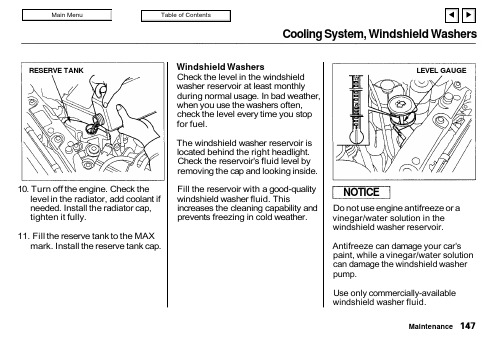
Cooling System, Windshield Washers10. Turn off the engine. Check the level in the radiator, add coolant if needed. Install the radiator cap,tighten it fully.11. Fill the reserve tank to the MAX mark. Install the reserve tank cap.Windshield WashersCheck the level in the windshield washer reservoir at least monthly during normal usage. In bad weather,when you use the washers often,check the level every time you stop for fuel.The windshield washer reservoir is located behind the right headlight.Check the reservoir's fluid level by removing the cap and looking inside.Fill the reservoir with a good-quality windshield washer fluid. Thisincreases the cleaning capability and prevents freezing in cold weather.Do not use engine antifreeze or a vinegar/water solution in the windshield washer reservoir.Antifreeze can damage your car's paint, while a vinegar/water solution can damage the windshield washer pump.Use only commercially-available windshield washer fluid.MaintenanceRESERVE TANKLEVEL GAUGENOTICETransmission OilAutomatic TransmissionCheck the fluid level with the engine at normal operating temperature.1. Park the car on level ground. Shut off the engine.2. Remove the dipstick (yellow loop)from the transmission and wipe it with a clean cloth.3. Insert the dipstick into the transmission.4. Remove the dipstick and check the fluid level. It should be between the upper and lower marks.5. If the level is below the lower mark, add fluid into the tube to bring it to the upper mark. Use Honda Premium Formula Auto-matic Transmission Fluid or an equivalent DEXRON ® II Auto-matic Transmission Fluid (ATF)only.6. Insert the dipstick back in thetransmission. Make sure the notch fits in the dipstick guide and the dipstick is down all the way.The transmission should be drained and refilled with new fluid every 24months or 48,000 km (30,000 miles),whichever comes first. Shorten this to every 12 months or 24,000 km (15,000 miles) under severe driving conditions (see page 134).MaintenanceDIPSTICKUPPER MARKLOWER MARKTransmission Oil, Brake and Clutch Fluid5-speed Manual TransmissionCheck the oil level a couple of mi-nutes after shutting off the engine.Make sure the car is on level ground.Remove the transmission filler bolt.The oil level should be up to the edge of the bolt hole. Feel inside the bolt hole with your finger. If you do not feel any oil, slowly add oil until it starts to run out of the hole. Reinstall the filler bolt and tighten it securely.Only use an API Service SF or SG grade motor oil with a viscosity of SAE10W-30 or 10W-40.The transmission should be drained and refilled with new oil every 24months or 48,000 km (30,000 miles),whichever comes first. Shorten the service interval to every 12 months or 24,000 km (15,000 miles) under severe driving conditions (see page 134).Brake and Clutch FluidCheck the fluid level in the reser-voirs monthly. There are three reser-voirs. They are:Brake fluid reservoirClutch fluid reservoir (manual transmission only)ABS reservoirThe brake fluid in the brake and Anti-lock brake systems should be replaced every 2 years or 48,000 km (30,000 miles), whichever comes first.MaintenanceFILLER BOLTCorrectlevelBrake and Clutch FluidBrake SystemThe fluid should be between the MIN and MAX marks on the side of the reservoir. If the level is at or below the MIN mark, it is anindication that your brake system needs attention. Have the brake system inspected for leaks or worn brake pads.If you add brake fluid to bring it up to the MAX mark, use Genuine Honda Brake Fluid or an equivalent from a sealed container that ismarked DOT3 or DOT4 only. Brake fluid marked DOT5 is not compatible with your car's braking system.Anti-lock Brake SystemThe fluid should be between the MIN and MAX marks on the side of the reservoir. If it is at or below the MIN mark, it indicates a possible problem in the ABS. Have the dealer inspect the system and add fluid.MaintenanceMAXMINMAXMINBrake and Clutch Fluid, Power SteeringClutch SystemThe fluid should be between the MIN and MAX marks on the side of the reservoir. If it is not, add brake fluid to bring it up to that level. Use the same DOT3 or DOT4 brake fluid from a sealed container specified for the brake system.Low fluid level can indicate a leak in the clutch system. Have this system inspected as soon as possible.Power SteeringYou should check the fluid level in the power steering reservoirmonthly. Check the level when the engine is cold. Look at the side of the reservoir. The fluid should be between the UPPER LEVEL and LOWER LEVEL. If it is below the LOWER LEVEL, add power steering fluid to the UPPER LEVEL.CONTINUEDMaintenanceMAX MINLOWER LEVELUPPER LEVEL。
Perfect Aire PEVP240 蒸汽冷气器用户手册说明书
EVAPORATIVEAIR COOLERFOR MODELS:PEVP240READ AND SAVE THESE INSTRUCTIONS:Before using your evaporative cooler, pleaseread this manual carefully and keep it forfuture reference, along with your receipt.IMPORTANT SAFETY INSTRUCTIONS1. DO NOT attempt to repair or modify the machine. Contact an authorized service technician for repair of this unit.2. DO NOT operate the unit or unplug the cord with wet hands as this may cause electric shock.3. If the power cord is frayed or damaged stop use of the unit immediately. Turn the unit off, unplug the cord and replace the cord; replacement work should be performed by authorized service technician.4. ALWAYS turn off the unit when cleaning, performing maintenance or moving the unit.5. Unplug the power cord and empty the water tank if the unit will not be in use for an extended period.6. DO NOT insert any foreign objects into the air inlet or outlet to prevent accidental personal injury or damage to the unit, this may cause electric shock and/or damage to the unit.7. DO NOT use this unit in environments with flammable and explosive gases. Avoid direct sunlight on the unit.8. DO NOT place this unit on an incline or other uneven surface to prevent the unit from tipping and falling causing damage to the unit or internal parts.9. DO NOT use outdoors. This unit is intended for indoor use only.10. This unit has a safety switch. If the filter frame is not installed correctly, the unit will not work as intended; DO NOT remove the filter frame while the unit is operating.11. DO NOT exceed the "MAX" water level indicator, during humidification, the total water level in the tank shall be controlled and shall not go below the "MIN" water level indicator.12. ALWAYS unplug the unit when refilling the tank and moving the unit.13. DO NOT tilt or bump the unit when placing or moving it. After the water tank is filled with water, move the unit slowly and carefully from the side to prevent spillage.14. When using the unit, prohibit overturning to avoid any accidents. If the unit topples over accidentally, and it contains water, unplug the power cord immediately and stand right side up. Wait until the unit is fully dry before attempting to run the unit.15. DO NOT place items on the unit, and covering the outlet is strictly prohibited.16. Use a moist soft cloth with mild soap when cleaning the unit; use a dry cloth to wipe down the excess. NEVER use corrosive cleaning agents or solvents. NEVER rinse the unit with water.17. DO NOT have the air inlet or outlet too close to walls, curtains and other objects, as they may block the airflow and affect air supply or burn the motor.18. When the unit is running, do not knock or shock the body of unit forcibly as it may lead to an automatic shutdown, in which case simply restart the unit.19. In summer, the water in the tank may easily deteriorate and generate odor, regularly change the water; it is best to use warm water for humidification if the indoor temperature is below zero in the winter.20. DO NOT place the unit directly below a power outlet.21. DO NOT use the unit around tubs, sprinklers or swimming pools.22. Product repair must be carried out by an authorized service technician.23. If the power cord is damaged, it must be replaced by the manufacturer, an authorized service technician or a similarly qualified person to avoid hazard and voiding the warranty.24. To protect against the risk of electrical shock, do not immerse the unit, cord or plug in water or other liquid.25. This unit is not intended for use by persons (including children) with reduced physical, sensory or mental capabilities, or lack of experience and knowledge, unless they have been given supervision or instruction concerning use of the appliance by a person responsible for their safety. Young children should be supervised to ensure that they do not play with the unit.26. ALWAYS unplug the unit from the outlet when the unit is not in use and before performing maintenance.27. Keep electrical appliances out of reach from children or disabled persons. DO NOT allow them to use the unit without supervision.28. ALWAYS unplug the unit when filling, refilling and cleaning the unit.29. ALWAYS unplug the unit prior to cleaning or performing other maintenance, the unit must be disconnected from the power outlet.Distributed by:Perfect Aire, LLC5401 Dansher Rd.Countryside, IL 60525844-4PA-AIRE | 844-472-2473PA/User_PEVP240/02282019。
- 1、下载文档前请自行甄别文档内容的完整性,平台不提供额外的编辑、内容补充、找答案等附加服务。
- 2、"仅部分预览"的文档,不可在线预览部分如存在完整性等问题,可反馈申请退款(可完整预览的文档不适用该条件!)。
- 3、如文档侵犯您的权益,请联系客服反馈,我们会尽快为您处理(人工客服工作时间:9:00-18:30)。
Air-water Coolers Installation Operation Maintenance ManualCONTENTS1 General2 Installation and removal of cooler3 Commissioning4 Protective film5 Standstill6 Service control6.1 General6.2 Performance test7 Cleaning7.1 General7.2 Cleaning of the water side7.2.1 Mechanical cleaning7.2.2 Hydraulic cleaning7.2.3 Chemical cleaning7.2.3.1 Chemical cleaning -Insitu7.2.3.2 Chemical cleaning-Cooler removed7.3 Cleaning of the air-side7.3.1 General7.3.2 Hydraulic cleaning7.3.3 Chemical cleaning1. GeneralThe water cooler is a finned tube heat exchanger .The hot air flows through the fins on the outside of the tubes and the cooling fluid flows through the tubes. The heat exchanger surface of the cooler consists of elliptical core tubes with rectangular threaded on fins or round core tubes with either wound-on fins or continuous flat plate fins. The bond between fin and tube is achieved either by mechanical means or by soldering.The core tubes are rolled into the tube sheets at each end of the tubes with roller.Side wall form an integral part of the cooler and are bolted to tube sheets.Water Headers (Namely connection and Return headers) are provided for water handling. The number of separation baffles conforms to the number of water passes. The headers are bolted to the tube sheets, gaskets interposed to form a seal. Plugs in the header are provided for cooler venting and draining.The materials for headers, tube, sheets and core tubes are chosen in accordance with the specification of the cooling water to be used and the recommended water velocity in the tubes.2.Installation and removal of the coolerRead all the maintenance instructions before you begin bundling this product.The cooler should be installed where it is accessible for cleaning, but not where the general public has access to it. Only let trained personnel with profound knowledge of the product and the appropriate safety rules carry out any work on the cooler.Prior to installation of the cooler ,the transport covers of the air side and the blanks on the water connection flanges are to be removed .The air and water side sealing surfaces ,which areprotected priot to shipping, must be cleaned by the use of turpentine.The cooler can either be mounted to the engine as a self mounted in the air duct as a cantilever unit. The air side connections are bolted to the air ducts using gaskets or sealing compound provided by the engine builder.The cooling water pipes are bolted to connection flanges on the connection header using gaskets also provided by the engine builder.To avoid deformation and stresses when installing the cooler all connecting surfaces must be parallel and the tolerances should be kept as small as possible.All connections are to be air and water tight. Transport lugs are provided on the side walls forlifting and handling of the complete cooler. Lifting lugs are also welded to the tube stack side walls. Prior to installation of the cooler casing into the air duct the tube stack can be removed by means of unscrewing the bolts holding the protruding tube sheet to the casing frame and removal of the gland packing or cover plate at the extension end tube sheet. At the fixed end of tube stack threads are provided in the water header for eyebolts to be used when lifting and pulling out.3. CommissioningThe cooler is subject to a hydraulic pressure test in our factory. It is however recommended to carry out a test with the specified test pressure before installation.If after prolonged storage or extended standstill the geared gaskets are leaking, tightening of the geared bolts might prevent further leakage. If this is not sufficient the header gaskets must be replaced. A pressure test with specified test pressure should be carried out after replacement.When refitting the headers ,tighten the bolts in the order .Tightening torque :70NmAfter assembly of the cooler is completed the cooler is circulated with the specified cooling water quantity prior to venting.For cooler venting, the vent plugs in the headers are removed. After the air has escaped from the cooler the plugs are fitted again. Venting should be repeated shortly after cooler is taken into operation. Venting of the complete cooling system is better than venting only thecooler and should therefore be preferred.With multi-circuit or multi-stage coolers, each circuit or stage should be vented separately.After a leak test has been carried out on all plant components, and the water flow has been checked to en-sure there are no restrictions, the cooler can be put into operation.Upon accelerating the engine to the nominal load the air temperature should be measured before and after the cooler and the cooling water flows set in accordance with the nominal water flows stated in the performance data sheet for the cooler in question.Never operate at min. velocity for a prolonged period of time. The nominal water flow stated in the performance data sheet for the cooler in question should be maintained.Frequent fluctuation of the water velocity impede the formation of a protective film on the tube inside, which are vital for corrosion protection. A too low water velocity encourages dirt deposits and a too high velocity causes erosion. To throttle the water flow or improper position of the water intake could lead to oxygen enriched water which favors corrosion. To keep the water flow, and so the watervelocity, constant also during part load operation ,control devices should be installed.4. Protection filmMeasures to assure the formation of a strong and durable protective film.The inherent good chemical corrosion-resistance of cop-per and copper alloys is due to their ability to form a natural protective film which is difficult to dissolve.New cooler tubes lacking a sufficiently strong protective film should never be operated with contaminated water, as deposits on the material surface would prevent the formation of such a protective film.For the above reason clean fresh water is used for the hydraulic test of the heat exchanger. The utilization of contaminated water should also be avoided during test runs. During test runs it is recommended to add small quantity of easily soluble ferrous sulphate (FeSO4.7H2O) to the cooling water to make sure that a good protective film is formed before operating with contaminated water.It is sufficient to add about 5mg/l to cooling water during a period of one hour every 24 hours. Adding of ferrous sulphate should, if possible, be repeated during normal operation until the first inspection is carried out.An appropriate valve for adding ferrous sulphate should be provided in the piping close to the water inlet nozzle of the cooler.5. StandstillA standstill of the cooling water system, leaving the cooler undrained, is hazardous for cooler parts made of copper , copper alloys, steel and cast iron.For copper and copper alloys standstills are especially hazardous prior to the formation of a protective film or in the case that the destruction of the same must be feared for reason of deposit attacked by putrefaction products such as ammonium compounds and hydrogen sulphide.If possible, cooler operation should not be interrupted during the first 2 months after commissioning if the cooler can not be drained.However, if there is a failure in cooling water supply and operation is resumed within 3 days and then for a prolonged period of time kept uninterrupted, the cooler may be left undrained.It must be then guaranteed that the tubes are free from deposits. If deposits have formed, the cooler should be drained, the tubes cleaned and flushed with clean water prior to being dried. We recommend the use of warm or pre-dried air for blowing through the tubes.The coolers need to be vented adequately. If sea water, brackish or saline water(chloride content>500mg/l) is used as cooling water, water with low salinity (drinking water quality)should be used for flushing. In case of standstill within the start-up period of 2 months which is expected to last for more than 3 days, and where deposits must be feared, the cooler should be drained, flushed and dried.To avoid standstill corrosion after the first 2 months of operation the above described cleaning procedure should be repeated by every standstill lasting longer than 2 weeks.In case of permanent service interruptions after the start-up period it may be necessary to limit the standstill where the cooler is kept undrained to 3 days and operate the unit under conditions as recommended for the start-up period.During short standstill the cooler can be operated at low cooling water velocity soformation of deposits in the tubes can be prevented. Operating with low water velocities is to be preferred to cooling water standstill in the tubes as putrefaction products, such as ammonium compounds and hydrogen sulphide are washed away from their point of origin.During winter time standstill if frost injury to the cooler could occur the cooler should be drained also during the shortest standstill.6.Service control6.1 GeneralFor service control, thermometers are to be installed in the air ducts and in the cooling water piping before and after the cooler, we recommend to keep record of the air and water temperatures in the machine log book periodically. Further control instruments can be provided in accordance with the individual requirement.In case of the occurrence of a major amount of condensate after the cooler, further condensation can be prevented ,or at least limited, by the use of a bypass control of the cooling water as previous described.A possibility to drain the condensate must be assured.6.2 Performance testThe performance guarantee given is main expressed by the temperature difference between cold water and cold air during normal operation and should be checkedfrom time to time.In the event that a considerable increase of the guaranteed temperature difference observed during normal operation ,this might be due to accumulation of air in the cooler. To remedy the above the cooler should be vented by using the procedure previously described.In case a performance increase cannot be achieved by proceeding as above and provided no other disturbance can be found , the cooler needs cleaning.A differential pressure gauge can also be used to check whether or not cleaning of the air or water side of the cooler is necessary. We recommend to install differential pressure gauges in the air duct and water piping before and after the cooler.7. Cleaning7.1 GeneralCleaning of the water and air side heat exchange surfaces is imperative for a long and trouble free operation of the cooler. The cleaning intervals vary with the mode of operation, cooling water quality, intake air characteristics etc.Cleaning can be done by either mechanical , hydraulical or chemical means.7.2 Cleaning of the water sideRegular cleaning is necessary. The cleaning intervals depend on the cooling water used. Cleaning of the water side is not only required to maintain the thermal performance of the cooler. Scaling increases the risk of biting corrosion and obstacles partly blocking the tubes favors erosion.7.2.1 Mechanical cleaningMechanical cleaning is done by use of nylon brushes fitted to a rod. The length of the rod corresponds to the tube length of the cooler in question and the type of brush is chosen in accordance with the finned tube type. The brush with rod is part of each cooler delivery.Mechanical cleaning can be done insitu or with the cooler removed. At least one header needs to be removed when cleaning. For header removal threaded holes with the same dimension as the header bolts are provided in the header flange to serve as jacking screws. The wet tubes should be thoroughly brushed clean one after the other and the dirt flushed out until no residues are left. After the cleaning is completed the headers are refitted using new gaskets. Venting must be repeated after cooling water is refilled7.2.2 Hydraulic cleaningHydraulic cleaning is carried out with the cooler removed using a high pressure spray gun with special nozzle to remove dirt deposits inside the tubes.7.2.3 Chemical cleaningChemical cleaning can be carried out in-situ or with the cooler removed.7.2.3.1 Chemical cleaning In-situTo ensure that the cooler is always operated without fouling or scaling in the tubes we recommend an integrated and continuously operating chemical cleaning system to be fitted.Such cleaning system comprises of a circuiting pump and a detergent tank with the necessary piping and shut off valves. The detergent circuit is connected to the cooling water inlet and outlet piping between their shut off valves and the water header flanges.Prior to cleaning, the cooling water flow is interrupted to allow the cooler to drain via the cooling water outlet piping. For draining the vent screw are removed. After draining, the cooling water valves are closed. The valves of the cleaning circuit are opened and the circulating pump switched on. The vent screws are fitted after venting completed.It is recommended to connect the cleaning circuit to the cooling water outlet piping in such a way that the deter-gent flow is opposite to the normal cooling water flow.When cleaning completed the cooler is drained leaving no detergent in the cooler. The valves of the cleaning circuit are closed and the cooling water valves opened. Flushing is done with normal cooling water. Reventing of the cooler is necessary.Scaling deposits in the cooling tubes can be removed by chemical cleaning as well. For removal, a 10% HCL hydrochloric, or muriatic acid is used and a 0.5% inhibitor (specifically suitable for the individual tube material added.After cleaning, the cooler is to be flushed thoroughly, i.e. no detergent residues are allowed to be left in the cooler.This is most important in case the cooler is shut down for a short time after cleaning.If the cooler is chemically cleaned in mounted position the headers need not be dismounted. For chemical cleaning we recommend to use suitable detergents to clean:The instructions and handling guidelines provided by the manufacturer of the detergent in question should always be observed when using the chemical.7.2.3.2 Chemical cleaning Cooler removedChemical cleaning while the cooler is removed is required if neither mechanical or hydraulic cleaning proved successful and if the cooler is not connected to a continuously operating cleaning system.The complete cooler with attached header will be connected by the use of blind flanges to an external cleaning circuit or filled with detergent on the water side. Time of saturation depends on the grade of deposit. If the result is not satisfying, cleaning should be repeated.7.3 Cleaning of the air-side7.3.1 GeneralCleaning of the air-side should be done early enough to avoid accumulations of soot and oil on the fins, which after a period of time form a hard crust that is difficult to remove, as well as the deposition of other crack products as for instance residues that form a sulphuric acid (compound with condensate) when left on the fins and tubes for some time.7.3.2 Hydraulic cleaningHydraulic cleaning is effected when the cooler is removed .A high pressure spray gun as described above is suitable also for this requirement. We recommend a nozzle size of 3mm. If the water jet attacks the cooling tubes vertically, i.e. in parallel to the fins, a pressure of 120bar is suitable to be applied at a distance of 2m from the fin surface.7.3.3 Chemical cleaningWe recommend chemical cleaning of the air side while the cooler is removed.The water headers are detached from the cooler bundle .The tube bundle is then immersed into a chemical cleaning bath. The time of immersion is a function of the degree of fouling. When cleaning completed, the cooler is to be flushed by applying a powerful water jet. If the result isstill not satisfying, cleaning should be repeated.To intensify the cleaning effect of the bath and shorten the cleaning time, it is recommended to circulate the detergent. The chemical detergents can also be applied by spraying. The following detergents are recommended for air side cleaning.The instructions and handling guidelines provided by the manufacturer of the detergent in question should always be observed when using the chemical.。