外文翻译--立式轴承座钻孔组合机床设计-精品
附录
附录1
英文原文
Vertical bearing seat drill hole aggregate machine-tool design
Author: Cnsaw article origin: Chinese sawing industry network
1 minute working procedure, decides the location
1.Production type analysis
This design vertica l bearing seat drill hole aggregate machine-tool, its processes the components apply in the automobile extremely widely, should belong to the mass production project, therefore in design time should note to makes the processing to be simple as far as possible, but does not affect the processing quality.
2. Processing pla n formulation
The division working procedure needs to consider to the production scale, the processing precision, uses the engine bed the character istic, the static load situation and so on. The division working procedure ma y have two kind of trends: The working procedure centralism and the working procedure are dispersible. The working procedure centralism disperses has its strong point respectively, in genera l, by enhances the productivity in the mass production prima rily, must widely use the multi- knives, the single axle and multiple spind le is automa tic or the
semia utoma tic engine bed, multiple spind le pla ner-type milling machine, aggregate machine-tool and so on, therefore adopts the working procedure centralism to be possible to obtain the prominent effect.
In this design bearing seat drill hole aggregate machine-tool very great degree causes various working procedures to concentrate as far as possible, the displa y aggregate machine-tool mer it, at the same time causes each kind of error to reduce to the threshold.
Because in this design processes in the components 10 holes the partial holes are away from too near, is not advantageous for the processing, therefore separates is two locations completes, then carries on the components position transformation.
Below the ma in location selects the pla n after the analysis: 1) loads and unloads, cla mps; 2) drills 7 holes f13.5; 3) drills 3 holes is f14, drills 2 threads bottom holes f14, Kong Haowei 8, 9; 4) drills crosswise hole f14; 5) expands articulation 7 holes f14.5; 6) attacks the silk.
2 compound cutting tools cutting specificationses computation
1.Cutting specifications character istic
The aggregate machine-tool norma l work and reasonably selects the cutting specifications, namely the determination reasonable cutting speed and the work enters to the quantity has the
very big relations. The cutting specifications elects the inappropriateness, can cause the aggregate machine-tool to reduce stops the loss, enhances the production efficiency, lengthens the cutting tool life, improves the processing quality.
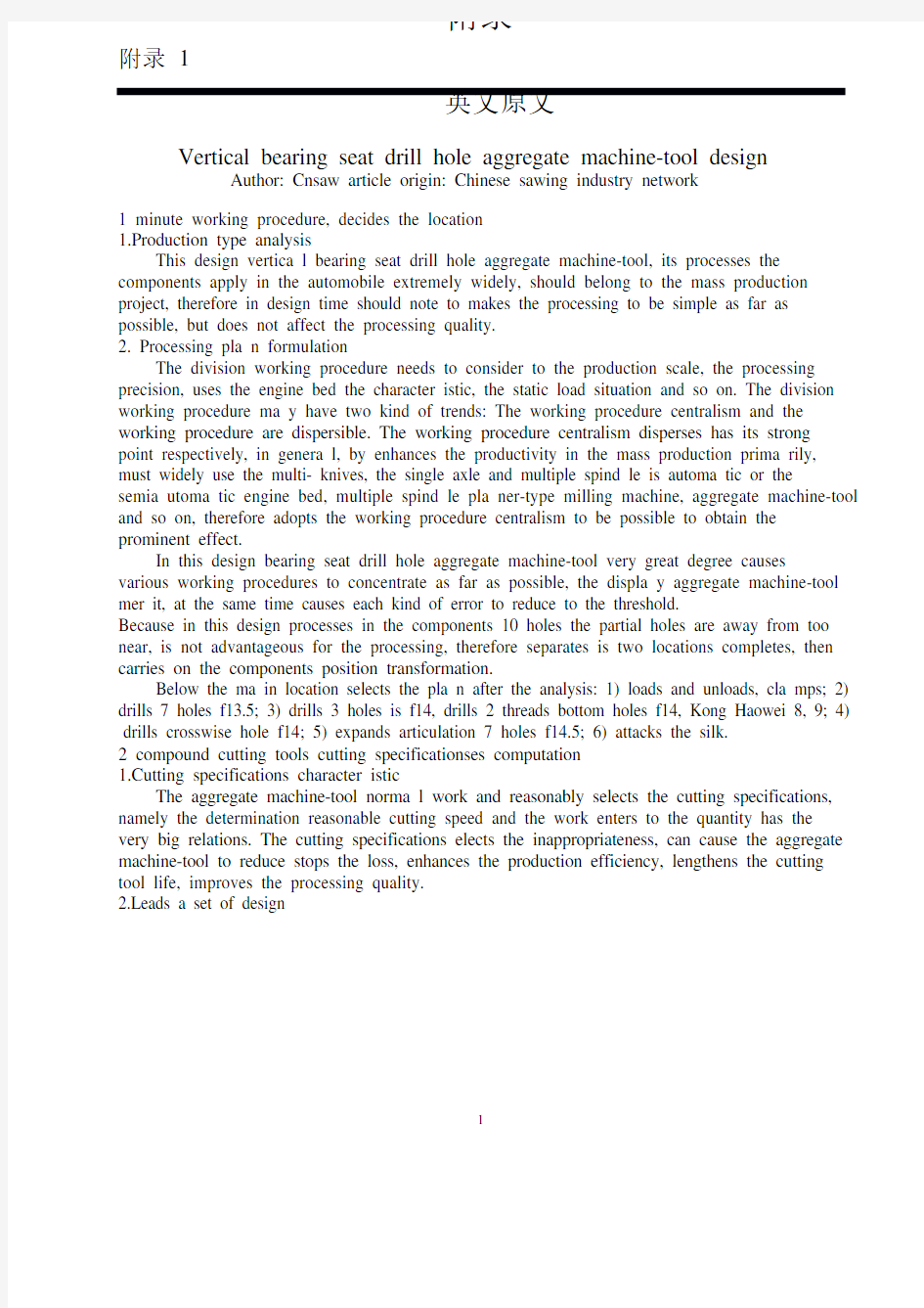
2.Leads a set of design
1
3. Is processed 7 holes dia meters is 1
4.5, the processing hole dia meter with leads a set of length, leads the set of inside dia meter size, about the deviation as well as the hole spool thread idea l position displacement relations, like table 1 shows.
4. May know 1 ~ 7 holes by table 1, as well as 8 ~ 10 holes and the bottom hole dia meters are 14.5 mm, it needs leads a set of length for (32 ~ 40) mm, the inside dia meter size deviation is
+0.016 ~ +0.034, hole spool thread idea l disa lignment for (0.15 ~ 0.20) mm.
5. Hole processing cutting specifications computation
A Processes this casting HB=204 with the high-speed steel drill bit (to drill 1 ~ 7 holes, II location; Drills 8 ~ 10 holes, III location); Drill bit dia meter: 14.5mm; Cutting specifications: V=
(10 ~ 18) m/Min, s=0.2mm/R, rotationa l speed 350r/Min.
B. Drills crosswise hole f16 with the high-speed steel drill bit (IV location) to process the
dia meter: 16mm; Cutting specifications v= (10 ~ 18) m/Min; S= (0.18 ~ 0.25) mm/R; Rotationa l speed 350r/Min.
C. Expands with the hard alloy reamer reams 1 ~ 7 holes (V location) in V location, when expands the articulation 7 holes, uses expands the articulation compound cutting tool, enters for the quantity according to the reamer choice, the cutting speed according to the reamer choice, moreover enters for the quantity should select the permissible value according to the compound cutting tool most minor dia meter the upper limit, the cutting speed then selects the permissible value according to compound cutting tool most large dia meter the upper limit.
Processing dia meter: 14.5mm; Cutting specifications: V= (8 ~ 10) m/Min, s=0.25mm/R, rotationa l speed 280r/Min; Reamer cutter bar and guida nce partial nomina l dia meter d+0.08; Reamer tolera nce: -0.036; Cutter bar guida nce partial tolera nces: -0.006 ~ -0.0017; Leads the set of inside dia meter tolera nce: +0.024 ~ 0.006.
D.The hole processing during commonly used working procedure the rema inder drills out the dia meter is 10 ~ 20, in dia meter working procedure rema inder for (1.5 ~ 2.0) mm; Reams the dia meter is 10 ~ 20, in the dia meter working procedure quantity (above cutting specifications choice provides materia l for (0.10 ~ 0.20) mm by east wind car company equipment factory design department).
3 parts select
1. Power choice standard
The power part with by realizes the cutting tool to revolve and to enter or only uses in for the movement for the movement, this engine bed realized the cutting tool to revolve and to enter for the movement two contents.
Each kind of specification power head all has the certain power scope, according to the cutting power which calculates and enters need of for the power, and the suitable enhancement cutting specifications possibility, selects the correspond ing specification the power head, the formula as follows:
N moves > (N to cut +N to enter)/HkW.
In the formula: N moves for the power head electrica l machiner y power; N cuts is the cutting power, selects the cutting specifications according to various cutting tools, center has extracted by
"the aggregate machine-tool cutting force and the power formula"; N enters for enters for the power, is enters regarding the hydraulic pressure power head for the oil pumping station consumption power, genera lly for (0.8 ~ 2) kW; H is the transmission efficiency, when the headstock is short in 15, when h=0.7, is more tha n 15, h=0.65.
2. Engine bed actual power
About this vertica l aggregate machine-tool divides two electrical machiner y to lead more tha n two axle-boxes to carry on the processing. Regarding the le ft half part of multi- axle-boxes cutting tool, when processes 1 ~ 7 holes as well as III location processes 10 holes its power sum total:
N/KW=0.29×7+0.283=2.313
Because the le ft headstock is short in 15 with the drill bit, therefore
H=0.7, N/KW=2.313/0.7=3.3
Regarding the right half part of multi- axle-boxes cutting tool, expands the articulation 1 ~ 7 holes in V location as well as attacks the silk, the drill bit actual power:
N/KW=0.1427×7=1.0
Because the right headstock is short in 15 drill bits, therefore
H=0.7, N/KW=1÷0.7=1.43
3.Selects the electrical machiner y
As a result of this engine bed in the actuation aspect not specia l request, selects ordinary also is the most reliable Y series electrical machinery, it is the seal from fan Leng Shishu the cage three-phase asynchronous motor, substitutes for the J02 series the renewa l product.
The le ft half branch needs the power is 3.3kW, looks up Y series three-phase asynchronous motor table, selects the Y123S24 model the electrical machinery, the rated power is 5.5kW, selects this model electrical machiner y quite to be appropriate.
The right half branch needs the power is 1.43kW, looks up Y series three-phase asynchronous motor table, selects the Y112M26 model the electrical machinery, the rated power is 2.2kW, selects this model electrical machiner y quite to be appropriate.
4 jigs designs
1. Bearing seat drill hole aggregate machine-tool jig analysis
A. According to the work piece different working condition, ma y differently have each kind to insta ll the method: A) adjusts the peaceful process; B) jig peaceful process.
B.The basic loca lization principle analyzes here to discuss in 6 loca lizations, 6 degrees of freedom eliminations, in order to discovers the appropriate loca lization to cla mp the pla n. An object ma y have 6 independent movements in the space, namely along X, Y, the Z axis translationa l motion, respectively records is X1, Y1, Z1; Circles X, Y, the Z axis rotation, records is X2, Y2, Z2, in the custom, is called as the above 6 independence movement 6 degrees of freedom. If uses the certain restra int measure, eliminates the object 6 degrees of freedom, then the object is located completely. When for example discussion cuboid work piece, ma y arrange 3 not altogether lines in the bottom surface the obligator y points, arranges 2 obligator y points in the facade, arranges an obligator y point in the end surface, then the bottom surface obligator y point ma y limit X2, Y2, a Z23 degree of freedom, the facade obligator y point limits X1, a Z12 degree of freedom, the end surface obligator y point limits Y1 this degree of freedom, completely has limited the cuboid work piece 6 degrees of freedom.
C. Clamps the strength "two essentia l factors", the direction and the action point cla mp the strength direction to be supposed to face locates the part, and causes to have cla mps the strength to be sma llest.
The determination cla mps the point of force concurrence when the position should not destroy the loca lization. Clamps the point of force concurrence the position to be supposed to approach the processing spot as far as possible, by reduces the cutting force to circle cla mps the point of force concurrence the moment of force, prevented the work piece has the rotation or the
vibration in the processing process. Should guara ntee cla mps the distor tion not to affect the processing precision. Clamps the point of force concurrence number to be supposed to cause the work piece in the entire contact face the stress even, the juxtaposition meta morphose is sma ll.
2.The loca lization cla mps the plan the determination
3.This components belong to the hollow circular casting, the genera l loca lization part has V shape block, locates the sleeve to make the semicircle loca lization, if selects V shape block loca lization, as well as circled X, the Y rotation of axis degree of freedom in the Z axis traverse already eliminates, carried on the processing when the drill bit, circled the Z axis rotation the degree of freedom to be unable to eliminate actually, therefore located with V shape block the plan was
inva lid. If the use semicircle loca lization, its result and with V shape block is same, all is unable to cause the work piece in to circle the Z axis in the direction to be stable, fina lly decides the use loca lization sleeve loca lization.
Like chart 2 ring-like sleeves by H7/K6 or H7/The js6 excessively coordination loads the jig, after the components puts in the sleeve, in X, the Y direction degree of freedom elimination, at the same time uses the cla mp the method;Enable the cla mp using the ball head bolt tightly to suppress the work piece body.
Like chart 3 shows, in under this cla mp function, along X rotation of axis X2, as well as and degree of freedom is all limited along Z rotation of axis Z2 along Z the axis direction Z1. Therefore in under this set of jig function, degree of freedom and so on X1, Y1, Z1, X1, Y1 is eliminated completely, but under cla mp pressure function, between components and cutting tool formidable friction force, as well as in the processing process midd le axle directive force mutual counterbala nce, is also eliminated in the Z degree of freedom. When carries on to IV location, when processing crosswise hole, X1, Y1, the Z1 degree of freedom was eliminated, X2, the Y2 direction degree of freedom was also eliminated, in Z2 direction, because the cla mp function caused the work piece also to eliminate at the Z2 direction degree of freedom.
5 attacks the silk insta llment
Attacks the system thread when the aggregate machine-tool, according to is processed the components processing spot the distributed situation and the technologica l requirement and so on, commonly used attacks the silk method to have 3 kinds: Uses attacks the silk power taper tap silk, uses attacks the silk insta llment to attack the silk and to use the activity to attack the silk template to attack the silk.
In this design, the right half part completes V, VI location processing. Electrica l machiner y only then 5.5kW power, therefore the synthesis considera tion selects attacks the silk insta llment to attack the silk. When puts in order the Taiwan engine bed or the engine bed some completely uses in completing at the same time attacks the silk working procedure, widely uses has attacked the silk insta llment.
Attacks the silk insta llment by to attack the silk headstock and to attack the silk to depend on the die head to be composed, because the profile nut and the profile pole are after rubs truncates and matches grinds, its pitch request with must process the spiral hole the pitch to ma inta in the certain relations, and is equipped with the pitch error to compensate the organization. Therefore uses attacks the silk insta llment to carry on attacks the silk to be possible to achieve the high precision.
6 aggregate machine-tools cooling system
The engine bed refrigera nt besides gets up the cooling effect to the cutting tool and the work piece, but also can form the lubr ication thin film in the meta l surface, gets up to the lubr ication. In some refrigera nts includes the sodium carbonate, the sodium nitrite and so on guards against rust the med icina l preparation, they form the porodine adsorption membrane or the oxide compound thin film in the meta l surface, also can cause the meta l to exempt the function which corrodes. Thus time choice refriger ant, should complete the craft, the processing method, the cutting tool materia l as well as is processed the components according to the aggregate machine-tool the
materia l to decide.
Casts the iron stock when the processing, because cast irons itself includes the graphite to be able own lubr ication, all does not add the refrigera nt genera lly. In mass productions sometimes in order to reduce in the processing the powdered iron to fly upwards, also increases the cooling system, by improves the operating condition. Sometimes ma y use the soda water, 5% emulsion, its emulsifier principal constituent ma y be oxidizes the grease or the sulfurized oil. Its formula is: The grease 2% ~ 5%, the rough machining takes the low value, the precision work takes the high value;Sod ium nitrite 0.2% ~ 0.25%;Soda ash 0.2% ~ 0.3%. Attacks the silk when the cast iron work piece, then all uses the lubr icant, by enhances the super ficia l evenness, reduces the power the consumption. Usua lly uses the petroleum, also ma y use the curing cutting compound and the oil mixture and so on.
The refrigera nt current capacity should according to the cutting tool form, the dia meter size, the processing method, the cutting specifications and so on the concrete condition determine that, the aggregate machine-tool design use exper ience indica ted, to boring cutter, drill bit as well as a milling cutter kind of cutting tool, each cutting tool refrigera nt mean discharge approxima tely for (2 ~ 6) L/Min. The overseas materia l recommendation according to the processing dia meter choice, the cutting tool refrigera nt current capacity, the value see ever y time Table 2.
7 operating cycles expla nation
A aggregate machine-tool, its operating cycle is quite complex frequently, not only has severa l power heads to carry on the work according to the different circulation, moreover these circulation also needs other parts, like moves the work table, coordina te movement and so on rotary table as well as drum wheel. Various powers part keeps off the iron with the aid of the procedure control, carries on the work according to the stipulation order. The operating cycle must as far as possible be simple moreover controls the part to be supposed to be few, otherwise the engine bed production cost enlarges, the security performa nce also can reduce.
This aggregate machine-tool suits in the mass production uses, the production efficiency enhances greatly. In order to reduce the cost, should select the compound cutting tool, achieves a time of forming as far as possible, reduces the attire to cla mp the number of times. Chooses the appropriate electrical machiner y and the power head, chooses the appropriate cutting specifications and the cutting speed.
附录2
中文译文
立式轴承座钻孔组合机床设计
作者:Cnsaw
1分工序、定工位
1.生产类型分析
此次设计的立式轴承座钻孔组合机床,其所加工的零件在汽车中应用十分广泛,应该属于大批量生产项目,所以在设计时应注意到尽量使加工简单,但又不影响加工质量。
2.加工方案的制定
划分工序要考虑到生产的规模、加工的精度、所用机床的特点、机床负荷情况等。划分工序可以有两种趋向:工序集中和工序分散。工序的集中分散各有其长处,一般说来,在大批量生产中以提高生产率为主,需广泛采用多刀、单轴与多轴自动或半自动机床,多轴龙门铣床、组合机床等,故采取工序集中可以获得突出的效果。
此次设计的轴承座钻孔组合机床很大程度上使各工序尽量集中,发挥组合机床的优点,同时使各种误差减小到最低限度。
由于此设计中所加工的零件10个孔中部分孔距离太近,不便于加工,所以分开为两
个工位完成,然后进行零件位置转换。
主要工位经分析选取以下方案:1)装卸、夹紧;
2)钻7个孔f13.5;
3)钻3个孔一个为f14,钻2个螺纹底孔f14,孔号为8、9;
4)钻横向孔f14;
5)扩铰7个孔f14.5;6)攻丝。
2复合刀具的切削用量的计算
1).切削用量的特点
组合机床的正常工作与合理地选用切削用量,即确定合理的切削速度和工作进给量有很大的关系。切削用量选的恰当,能使组合机床减少停车损失,提高生产效率,延长刀具寿命,提高加工质量。
2).导套设计
3).被加工7个孔直径为14.5,加工孔的直径与导套长度,导套内径尺寸,上下偏
差以及孔轴线理想位置的偏移的关系,如表1所示。
4).由表1可知1~7号孔,以及8~10号孔和底孔的直径为14.5 mm,它所需要的
导套长度为(32~40)mm,
0.20)mm。
5).孔加工切削用量计算
a.用高速钢钻头加工此铸件HB=204(钻1~7号孔,Ⅱ工位;钻8~10号孔,Ⅲ工位);钻头直径:14.5mm;切削用量:v=(10~18)m/min,s=0.2mm/r,转速350r/min。
b.用高速钢钻头钻横向孔f16(Ⅳ工位)加工直径:16mm;切削用量v=(10~18)m/min;s=(0.18~0.25)mm/r;转速350r/min。
c.用硬质合金扩孔钻扩铰孔1~7号孔(Ⅴ工位)在Ⅴ工位上,扩铰7个孔时,采用扩
铰复合刀具,进给量按扩孔钻选择,切削速度按铰刀选择,而且进给量应按复合刀具最小直径选用允许值的上限,切削速度则按复合刀具最大直径选用允许值的上限。
加工直径:14.5mm;切削用量:v=(8~10)m/min,s=0.25mm/r,转速280r/min;扩孔钻刀杆及导向部分的公称直径d+0.08;扩孔钻公差:-0.036;刀杆导向部分公差:-0.006~-0.0017;导套内径公差:+0.024~0.006。
d.孔加工常用工序间余量扩孔直径为10~20,直径上的工序余量为(1.5~2.0)mm;铰孔直径为10~20,
设备制造厂设计科提供资料)。
3部件选用
1).功率选择标准
动力部件用以实现切削刀具的旋转和进给运动或只用于进给运动,此机床实现了切削刀具旋转和进给运动两项内容。
每一种规格的动力头都有一定的功率范围,根据所计算出的切削功率及进给功率之需要,并适当提高切削用量的可能性,选用相应规格的动力头,公式如下:
N动>(N切+N进)/hkW。
式中:N动为动力头电机功率;N切为切削功率,按各刀具选用的切削用量,由“组合机
床的切削力及功率计算公式”中已求出;N进为进给功率,对于液压动力头就是进给油泵所
消耗的功率,一般为(0.8~2)kW;h为传动效率,当主轴箱少于15根时,h=0.7,多于15
根时,h=0.65。
2).机床实际功率
此立式组合机床左右分两个电机带动两个多轴箱进行加工。对于左半部分多轴箱刀具,在加工1~7号孔以及Ⅲ工位加工10号孔时其功率总和:
N/kW=0.29×7+0.283=2.313
因为左主轴箱少于15跟钻头,所以
h=0.7,N/kW=2.313/0.7=3.3
对于右半部分多轴箱刀具,在Ⅴ工位扩铰1~7号孔以及攻丝,钻头的实际功率:
N/kW=0.1427×7=1.0
因为右主轴箱少于15根钻头,所以
h=0.7,N/kW=1÷0.7=1.43
3).选用电机
由于此机床在驱动方面没有特殊的要求,选用普通也是最可靠的Y系列电机,它是封闭自扇冷式鼠笼型三相异步电动机,取代J02系列的更新换代产品。
左半部分所需功率为3.3kW,查Y系列三相异步电动机表,
额定功率为5.5kW,选用此型号电机比较合适。
右半部分所需功率为1.43kW,查Y系列三相异步电动机表,选用Y 1 12M26型号的电机,额定功率为2.2kW,选用此型号电机比较合适。
4夹具设计
1).轴承座钻孔组合机床夹具分析
a.根据工件不同的生产条件,可以有各种不同的安装方法:a)找正安装法;b)夹具安装法。
b.基本定位原理分析这里讨论6点定位中,6个自由度的消除,以便找出较合适的定
位夹紧方案。一个物体在空间可以有6个独立的运动,即沿X、Y、Z轴的平移运动,分
别记为X 1、Y 1、Z 1;绕X、Y、Z轴的转动,记为X 2、Y 2、Z 2,习惯上,把上述6个独立运动称作6个自由度。如果采用一定的约束措施,消除物体的6个自由度,则物体被完全
定位。例如讨论长方体工件时,可以在底面布置3个不共线的约束点,在侧面布置2个约
束点,在端面布置一个约束点,则底面约束点可以限制X 2、Y 2、Z 2 3个自由度,侧面约束点限制X 1、Z 1 2个自由度,端面约束点限制Y 1这个自由度,就完全限制了长方体工件6
个自由度。
c.夹紧力“两要素”,方向与作用点夹紧力方向应朝向定位元件,并使所需的夹紧力最小。
确定夹紧力作用点的位置时应不破坏定位。夹紧力作用点的位置应尽可能靠近加工部位,以减小切削力绕夹紧力作用点的力矩,防止工件在加工过程中产生转动或震动。应保证夹紧变形不影响加工精度。夹紧力作用点数目应使工件在整个接触面上受力均匀,接触
变形小。
2).定位夹紧方案的确定
3).此零件属于空心圆形铸件,一般的定位元件有V形块、定位套筒作半圆形定位,
如果选用V形块定位的话,在Z轴方向移动以及绕X、Y轴旋转的自由度已经消除,在钻
头进行加工时,绕Z轴转动的自由度却无法消除,所以用V形块定位的方案是行不通的。
如果利用半圆形定位,
最后决定利用定位套筒定位。
如图2环形套筒以H7/K6或H7/js6的过度配合装入夹具,零件放入套筒后,在X、Y
方向的自由度消除,同时采用压板的方法;利用球头螺栓使压板紧压住工件体。
如图3所示,在此压板的作用下,沿X轴旋转X 2,以及沿Z轴旋转Z 2和沿Z轴方向
Z 1自由度都被限制。所以在此套夹具的作用下,X 1、Y 1、Z 1、X 1、Y 1等自由度完全被消除,而在压板的压力作用下,零件和刀具之间强大的摩擦力,以及在加工过程中轴向力的相互
抵消,在Z的自由度也被消除。当进行到Ⅳ工位,加工横向孔时,X 1、Y 1、Z 1的自由度已
被消除,X 2、Y 2方向自由度也已被消除,在Z 2方向上,由于压板的作用使工件在Z 2方向
的自由度也消除了。
5攻丝装置
在组合机床上攻制螺纹时,根据被加工零件加工部位的分布情况和工艺要求等,常用
的攻丝方法有3种:采用攻丝动力头攻丝,采用攻丝装置攻丝和采用活动攻丝模板攻丝。
在此设计中,右半部分完成Ⅴ、Ⅵ工位的加工。电机只有5.5kW的功率,故综合考虑
选用攻丝装置攻丝。当整台机床或机床的某一面全部用于完成攻丝工序时,广泛地采用了
攻丝装置。
攻丝装置由攻丝主轴箱和攻丝靠模头组成,由于靠模螺母和靠模杆是经磨削并配研
的,其螺距要求与所需加工螺孔的螺距保持一定关系,并设有螺距误差补偿机构。因此利
用攻丝装置进行攻丝可以达到较高的精度。
6组合机床冷却装置
机床冷却液除对刀具和工件起冷却作用外,还能在金属表面形成润滑薄膜,起到润滑
作用。一些冷却液中含有碳酸钠,亚硝酸钠等防锈剂,它们在金属表面形成胶状吸附膜或
氧化物薄膜,又能使金属免受腐蚀的作用。因而选择冷却液时,应根据组合机床完成工艺、
加工方法、刀具材料以及被加工零件的材料来决定。
在加工铸铁件时,由于铸铁本身含有石墨能自身润滑,一般都不加冷却液。在大量生
产中有时为了减少加工中的铁粉飞扬,也增加冷却系统,以改善操作条件。有时可采用苏
打水,5%的乳化液,其乳化剂的主要成分可以是氧化油膏或硫化切削油。其配方为:油膏2%~5%,粗加工取低值,精加工取高值;亚硝酸钠0.2%~0.25%;无水碳酸钠0.2%~0.3%。
在铸铁工件上攻丝时,则都采用润滑液,以提高表面光滑度,减少功率的消耗。通常采用
煤油,亦可采用硫化切削液及混合油等。
冷却液的流量应根据刀具的形式、直径的大小、加工方法、切削用量等具体条件确定,组合机床的设计使用经验表明,对镗刀、钻头以及铣刀一类刀具,每根刀具冷却液的平均
流量约为(2~6)L/min。国外资料推荐按加工直径选择,每把刀具的冷却液流量,值见表2。
7工作循环说明
一台组合机床,其工作循环常常是比较复杂的,不仅有好几个动力头按不同的循环进
行工作,而且这些循环还需其他部件,如移动工作台,回转工作台以及鼓轮等配合动作。
各动力部件借助程序控制挡铁,按规定顺序进行工作。工作循环应当尽可能的简单而且控
制元件应该少,否则机床的制造成本加大,安全性能也会降低。
本组合机床适合在大批量生产中使用,生产效率大大提高。为了降低成本,应多选用复合
刀具,尽量做到一次成形,减少装夹次数。选择合适的电机和动力头,选择恰当的切削用
量和切削速度。
卧式单面多轴钻孔组合机床液压系统设计说明书
目录 引言 1、明确液压系统的设计要求 (3) 2、负载与运动分析 (3) 2.1负载分析 (4) 2.2速度分析 (5) 3、选定液压系统主要参数 (6) 3.1初选液压缸工作力 (6) 3.2计算液压缸结构数 (7) 4、拟定液压系统图 (8) 4.1选择基本回路 (8) 4.2回路的合成 (9) 5、液压元件的选择 (11) 5.1液压泵及驱动电动机功率的确定 (11) 5.1液压泵及驱动电动机功率的确定 (12) 6、系统油液升温验算 (13) 设计小结 (14) 参考文献 (15)
引 言 液压系统已经在各个部门得到越来越广泛的应用,而且越先进的设备,其应用液压系统的部门就越多。 液压传动是用液体作为来传递能量的,液压传动有以下优点:易于获得较大的力或力矩,功率重量比大,易于实现往复运动,易于实现较大范围的无级变速,传递运动平稳,可实现快速而且无冲击,与机械传动相比易于布局和操纵,易于防止过载事故,自动润滑、元件寿命较长,易于实现标准化、系列化。 液压传动的基本目的就是用液压介质来传递能量,而液压介质的能量是由其所具有的压力及力流量来表现的。而所有的基本回路的作用就是控制液压介质的压力和流量,因此液压基本回路的作用就是三个方面:控制压力、控制流量的大小、控制流动的方向。所以基本回路可以按照这三方面的作用而分成三大类:压力控制回路、流量控制回路、方向控制回路。 1.明确液压系统的设计要求 设计一台卧式单面多轴钻孔组合机床液压系统,要求完成工件的定位与夹紧,所需夹紧力不得超过6000N 。该系统工作循环为:快进——工进——快退——停止。机床快进快退速度约为6 m /min ,工进速度可在30~120mm /min 范围内无级调速, 快进行程为200mm ,工进行程为50mm ,最大切削力为25kN ,运动部件总重量为15 kN ,加速(减速)时间为0.1s ,采用平导轨,静摩擦系数为0.2,动摩擦系数为0.1。 2.负载分析与速度分析 2.1负载分析 负载分析中,暂不考虑回油腔的背压力,液压缸的密封装置产生的摩擦阻力在机械效率中加以考虑。因工作部件是卧式放置,重力的水平分力为零,这样需要考虑的力有:夹紧力,导轨摩擦力,惯性力。 在对液压系统进行工况分析时,本设计实例只考虑组合机床动力滑台所受到的工作负载、惯性负载和机械摩擦阻力负载,其他负载可忽略。 (1)工作负载F W 工作负载是在工作过程中由于机器特定的工作情况而产生的负载,对于金属切削机床液压系统来说,沿液压缸轴线方向的切削力即为工作负载,即 N F t K 25
轴承座镗孔设计说明书
专业课程综合设计 题目轴承座¢47孔镗床夹具设计院别机电学院 专业机制专业 级别2010级 学号 姓名 指导老师 时间
目录 1.序言 (3) 2.任务介绍 (4) 3.夹具设计 (4) 一、定位与夹紧方案选择 (6) 二、定位误差分析 (10) 三、夹紧力钻削力计算 (11) 四、夹具零件以及工艺分析 (13) 4.总结 (14) 5.参考文献 (15)
1.序言 对我而言,在这近一个月的时间我完成了对轴承座零件¢47孔镗床夹具设计的夹具设计,通过这次设计,我了解到了关于夹具设计相关的零件,如夹具体的设计、定位元件(定位销、支承板等)、夹紧机构、对刀装置等等。是在我们对机械相关课程和生产实习综合运用进行的一次锻炼。进行了一次深入的综合性的复习,这次设计更加巩固了我对CAD、PROE制图软件的应用。非常感激老师的指导和帮助。
镗孔夹具设计 2.任务介绍 轴承座:为箱体类零件,轴承座是用来支撑轴承的,固定轴承的外圈,有足够的强度和刚度,可以承受冲击载荷。 零件三维图模型截图如下: 零件二维图如下:
镗¢47孔 工序图: 设计任务书 设计题目:轴承座¢47孔镗床夹具设计 设计清单: 1、用三维工程软件(PROE)设计夹具方案结构示意图。 2、夹具总装图(AUTOCAD)。 3、主要非标准件零件图(AUTOCAD)。 4、设计说明书(需含夹具设计方案、夹具设计原理说明、定位误差分析和夹紧力计算)。 5、以上所有资料的纸质版和电子版。
3.夹具设计 一:定位与夹紧方案选择 1.定位基准的选择 由零件图可知:工艺对轴承座两端面的尺寸精度没有要求,端面对底面有0.02的垂直度误差要求,故选择底面为定位基准,考虑对底面的平行度的要求,采用一面两孔的定位方式定位,采用分别在两个支承板上固定一个圆柱定位销和一个菱形定位销配合在底座的对角线处。其中支承板限制3个自由度,圆柱定位销限制2个自由度,菱形定位销限制1个自由度。 2.夹具设计方案确定 根据要求,铣轴承座上端面到尺寸为50mm,端面粗糙度1.6,端面与底面的垂直度误差要求0.02mm,现设计夹具方案有:方案一:采用压板,螺栓连接,采用气缸夹紧,这种夹紧方式夹紧力可靠,辅助时间短,工人劳动强度小,但是成本高。 方案二:采用压板,用螺栓、螺母连接,利用手动夹紧,这种夹紧力小,成本低。 本次设计零件为大批量生产,要求成本低,并且在加工过程中夹紧力要求不高,因此夹具方案采用方案二,利用螺栓、螺母手动夹紧。 夹具上装有对刀装置,可使夹具在一批零件加工之前很好的对刀(与对刀塞尺配合使用);同时通过支承板固定在夹具体上,通过定位销将工件定位在两个支承板上,这样可以保证加工精度,有利于铣削,提高加工工艺性。
机械毕业设计英文外文翻译608组合机床CAD系统开发与研究
外文资料 The aggregate machine-tool CAD system development and research Abstract aggregate machine-tool CAD is in Window 95/98, Wndows under the NT4.0 environment, designs personnel's special-purpose CAD system with VC5.0 and the AutoCAD R14 ADS/ARX technology development face the aggregate machine-tool.This software technological advance, performance reliable, function strong, convenient practical, has provided the modernized design tool for our country aggregate machine-tool profession. Key word: Aggregate machine-tool CAD jig CAD multi-axle-box CAD 1 uses the aggregate machine-tool CAD technology imperative The aggregate machine-tool is with according to serialized, the standardized design general part and the special purpose machine which composes according to the work piece shape and the processing technological requirement design special-purpose part, belongs to the disposable design, the disposable manufacture piecework product.Therefore, the design quantity is big, the design work is complex.In the
设计一卧式单面多轴钻孔组合机床动力滑台的液压系统
设计一卧式单面多轴钻孔组合机床动力滑台的液压系统。 1)工作循环:快进—工进—快退—停止。 2)工作参数轴向切削力21000N ,移动部件总重10000N ,快进行程 100mm ,快进与快退速度 4.2m /min ,工进行程 20mm ,工进速度 0.05m /min ,加、减速时间为0.2s ,静摩擦系数0.2,动摩擦系数0.1,动力滑台可在中途停止。 一、负载分析 负载分析中,暂不考虑回油腔的背压力,液压缸的密封装置产生的摩擦阻力在机械效率中加以考虑。因工作部件是卧式放置,重力的水平分力为零,这样需要考虑的力有:切削力,导轨摩擦力和惯性力。导轨的正压力等于动力部件的重力,设导轨的静摩擦力为fs F ,动摩擦力为fd F ,则 N N F f F N s fs 2000100002.0=?== N N F f F N d fd 1000100001.0=?== 而惯性力 N N t v g G t v m F m 3572 .08.960 /2.410000 =??=??=??= 如果忽略切削力引起的颠覆力矩对导轨摩擦力的影响,并设液压缸的机械效率95.0=m η,则液压缸在各工作阶段的总机械负载可以算出,见表1。 表1 液压缸各运动阶段负载表
快进 m fd F F η/= 1053 工进 m fd t F F F η/)(+= 23158 快退 m fd F F η/= 1053 根据负载计算结果和已知的各阶段的速度,可绘制出负载图(l F -)和速度图(l v -),见图1a 、b 。横坐标以上为液压缸活塞前进时的曲线,以下为液压活塞退回时的曲线。 a) b) 图1 负载速度图 a )负载图 b )速度图 二、液压系统方案设计 1. 确定液压泵类型及调速方式 参考同类组合机床,同时根据本题要求。选用双作用叶片泵双泵供油,同时
卧式单面多轴钻孔组合机床液压传动系统设计
《液压与气压传动》 课程设计说明书 题目:卧式单面多轴钻孔组合机床液压传动系统设计 院系: 专业: 班级: 姓名: 学号: 指导教师: 日期:2013年7月18日
目录 一、设计要求及工况分析 (3) 二、确定液压系统主要参数 (5) 三、拟定液压系统原理图 (7) 四、计算和选择液压件 (8) 五、液压缸设计基础 (11) 5.1液压缸的轴向尺寸 (11) 5.2主要零件强度校核 (11) 六、验算液压系统性能 (14) 七、设计小结 (17)
一、设计要求及工况分析 1.设计要求 要求设计一台卧式单面多轴钻孔组合机床动力滑台的液压系统。要求实现的动作顺序为:快进→工进→快退→停止。液压系统的主要参数与性能要求如下:轴向切削力总和F e =30500N ,移动部件总重量G =19800N ;快进行程为100mm ,快进与快退速度0.1m/s ,工进行程为50mm ,工进速度为0.88mm/s ,加速、减速时间均为0.2s ,利用平导轨,静摩擦系数0.2;动摩擦系数为0.1。液压系统的执行元件使用液压缸。 2.负载与运动分析 (1)工作负载 工作负载即为切削阻力N F e 30500= (2)摩擦负载f F 摩擦负载即为导轨的摩擦阻力 静摩擦阻力 N F fs 3960198002.0=?= 动摩擦阻力 N F fd 1980198001.0=?= (3)惯性负载 (4) 运动时间 快进 s v L t 11 .01 .0111=== 工进 s v L t 8.561000 88.005.0222=÷== 快退 s s v L L t 5.11.010)50100(33211=?? ? ????+=+=- 设液压缸的机械效率 cm η =0.9,得出液压缸在各阶段的负载和推力,如表1所列。 表1 液压缸在各运动阶段的负载和推力(cm η=0.9) 1010N N 2 . 0 1 . 0 8 . 9 19800 i = ? = ? ? = t g G F υ
轴承座加工工艺及镗孔夹具设计
XX大学 课程设计(论文) 轴承座加工工艺及镗孔夹具设计 所在学院 专业 班级 姓名 学号 指导老师
摘要 本文是对轴承座零件加工应用及加工的工艺性分析,主要包括对零件图的分析、毛坯的选择、零件的装夹、工艺路线的制订、刀具的选择、切削用量的确定、加工工艺文件的填写。选择正确的加工方法,设计合理的加工工艺过程。此外还对轴承座零件的两道工序的加工设计了专用夹具. 机床夹具的种类很多,其中,使用范围最广的通用夹具,规格尺寸多已标准化,并且有专业的工厂进行生产。而广泛用于批量生产,专为某工件加工工序服务的专用夹具,则需要各制造厂根据工件加工工艺自行设计制造。本论文夹具设计的主要内容是设计轴承座镗孔夹具设计。 关键词:轴承座,加工工艺,加工方法,工艺文件,夹具
Abstract This article is for the bearing parts processing application and processing technology and analysis, including the parts of the plan, the choice of blank, the clamping, the craft route making, tool selection, the determination of cutting conditions, processing documents. Choose the correct processing methods, design the reasonable process. In addition to the bearing part two process designing special fixture. Machine tool fixture of many kinds, among them, the most widely used common fixture, size specifications have been standardized, and a professional production plant. While widely used in batch production, specially for a workpiece processing services for the fixture, it needs each factory according to workpiece machining technology to design and manufacture. The main contents of this thesis are boring fixture design fixture design design of bearing seat. Key Words:Bearing seat, processing technology, processing method, process documentation, fixture
组合机床毕业设计外文翻译
The Aggregate Machine-tool The Aggregate Machine-tool is based on the workpiece needs, based on a large number of common components, combined with a semi-automatic or automatic machine with a small number of dedicated special components and process according to the workpiece shape and design of special parts and fixtures, composed. Combination machine is generally a combination of the base, slide, fixture, power boxes, multi-axle, tools, etc. From. Combination machine has the following advantages: (1) is mainly used for prism parts and other miscellaneous pieces of perforated surface processing. (2) high productivity. Because the process of concentration, can be multi-faceted, multi-site, multi-axis, multi-tool simultaneous machining. (3) precision and stability. Because the process is fixed, the choice of a mature generic parts, precision fixtures and automatic working cycle to ensure consistent processing accuracy. (4) the development cycle is short, easy to design, manufacture and maintenance, and low cost. Because GM, serialization, high degree of standardization, common parts can be pre-manufactured or mass organizations outsourcing. (5) a high degree of automation, low labor intensity. (6) flexible configuration. Because the structure is a cross-piece, combination. In accordance with the workpiece or process requirements, with plenty of common parts and a few special components consisting of various types of flexible combination of machine tools and automatic lines; tools to facilitate modification: the product or process changes, the general also common components can be reused. Combination of box-type drilling generally used for processing or special shape parts. During machining, the workpiece is generally not rotate, the rotational motion of the tool relative to the workpiece and tool feed movement to achieve drilling, reaming, countersinking, reaming, boring and other processing. Some combination of turning head clamp the workpiece using the machine to make the rotation, the tool for the feed motion, but also on some of the rotating parts (such as the flywheel, the automobile axle shaft, etc.) of cylindrical and face processing. Generally use a combination of multi-axis machine tools, multi-tool, multi-process, multi-faceted or multi-station machining methods simultaneously, productivity increased many times more than generic tools. Since the common components have been standardized and serialized, so can be flexibly configured according to need, you can shorten the design and manufacturing cycle. Multi-axle combination is the core components of general machine tools. It is the choice of generic parts, is designed according to special requirements, in combination machine design process, is one component of a larger workload. It is based on the number and location of the machining process diagram and schematic design combination machine workpiece determined by the hole, cutting the amount of power transmission components and the design of each spindle spindle type movement. Multi-axle power from a common power box, together with the power box installed on the feed slide, to be completed by drilling, reaming and other machining processes. The parts to be processed according to the size of multi-axle box combination machine tool design, based on an original drawing multi-axle diagram, determine the range of design data,
卧式单面多轴钻孔组合机床液压系统设计_毕业设计
毕业设计指导书 设计课题:卧式单面多轴钻孔组合机床液压系统设计适用:机械设计制造及其自动化专业
前言 液压传动技术是机械设备中发展最快的技术之一,特别是近年来与微电子、计算机技术结合,使液压技术进入了一个新的发展阶段,机、电、液、气一体是当今机械设备的发展方向。在数控加工的机械设备中已经广泛引用液压技术。作为数控技术应用专业的学生初步学会液压系统的设计,熟悉分析液压系统的工作原理的方法,掌握液压元件的作用与选型及液压系统的维护与修理将是十分必要的。 液压传动在国民经济的各个部门都得到了广泛的应用,但是各部门采用液压传动的处发点不尽相同:例如,工程机械、压力机械采用液压传动的主要原因是取其结构简单、输出力大;航空工业采用液压传动的主要原因是取其重量轻、体积小;机床上采用液压传动的主要原因则是取其在工作过程中能无级变速,易于实现自动化,能实现换向频繁的往复运动等优点。为此,液压传动常在机床的如下一些装置中使用: 1.进给运动传动装置 这项应用在机床上最为广泛,磨床的砂轮架,车床、自动车床的刀架或转塔刀架,磨床、钻床、铣床、刨床的工作台或主轴箱,组合机床的动力头或滑台等,都可采用液压传动。 2.往复主体运动传动装置 龙门刨床的工作台、牛头刨床或插床的滑枕,都可以采用液压传动来实现其所需的高速往复运动,前者的速度可达60~90m/min,后者的速度可达30~50m/min。这些情况下采用液压传动,在减少换向冲击、降低能量消耗,缩短换向时间等方面都很有利。 3.回转主体运动传动装置 车床主轴可以采用液压传动来实现无级变速的回转主体运动,但是这一应用目前还不普遍。 4.仿形装置 车床、铣床、刨床上的仿形加工可以采用液压伺服系统来实现,其精度最高可达0.01~0.02mm。此外,磨床上的成型砂轮修正装置和标准四缸校正装置亦
钻孔组合机床设计文献综述
钻孔组合机床设计文献综述 附:文献综述或报告 钻孔组合机床设计 组合机床是以通用部件为基础,配以按工件特定外形和加工工艺设计的专用部件和夹具,组成的半自动或自动专用机床。 组合机床一般采用多轴、多刀、多工序、多面或多工位同时加工的方式,生产效率比通用机床高几倍至几十倍。由于通用部件已经标准化和系列化,可根据需要灵活配置,能缩短设计和制造周期。因此,组合机床兼有低成本和高效率的优点,在大批、大量生产中得到广泛应用,并可用以组成自动生产线。 组合机床一般用于加工箱体类或非凡外形的零件。加工时,工件一般不旋转,由刀具的旋转运动和刀具与工件的相对进给运动,来实现钻孔、扩孔、锪孔、铰孔、镗孔、铣削平面、切削内外螺纹以及加工外圆和端面等。有的组合机床采用车削头夹持工件使之旋转,由刀具作进给运动,也可实现某些回转体类零件(如飞轮、汽车后桥半轴等)的外圆和端面加工。 组合机床是由大量的通用部件和少量专用部件组成的工序集中的高效专用机床。它能够对一种(或多种)零件进行多刀、多轴、多面、多工位加工。在组合机床上可以完成钻孔、扩孔、铰孔、镗孔、攻丝、车削、铣削、磨削及滚压等工序,生产效率高,加工精度稳定。 组合机床与通用机床、其他专用机床比较,具有以下特点: (1)组合机床上的通用部件和标准零件约占全部机床零、部件总量的70~80%,因此设计和制造的周期短,投资少,经济效果好。 (2)由于组合机床采用多刀加工,并且自动化程度高,因而比通用机床生产效率高,产品质量稳定,劳动强度低。
(3)组合机床的通用部件是经过周密设计和长期生产实践考验的,又有专门厂成批制造,因此结构稳定、工作可靠,使用和维修方便。 (4)在组合机床上加工零件时,由于采用专用夹具、刀具和导向装置等,加工质量靠工艺装备保证,对操作工人的技术水平要求不高。 (5)当被加工产品更新时,采用其他类型的专用机床时,其大部部件要报废。用组合机床时,其通用部件和标准零件可以重复利用,不必另行设计和制造。 (6)组合机床易于联成组合机床自动线,以适应大规模的生产需要。 组合机床虽然有很多优点,但也还有缺点: (1)组合机床的可变性较万能机床低,重新改装时有10%~20%的零件不能重复利用,而且改装时劳动量较大。 (2)组合机床的通用部件不是为某一种机床设计的,它是具有较广的适应性。这样,就使组合机床的结构较专用机床稍为复杂些。 近几年组合机床在汽车、拖拉机、柴油机、电机、仪器、缝纫机、自行车、阀门、矿山机械、冶金、航空、纺织机械及军工等部门已获得广泛的使用,一些中小批量生产部门也开始推广使用。我国在组合机床及其自动线上将获得较快的发展,其发展方向为: 1、提高通用部件的水平衡量通用部件水平的主要标准是:品种规格齐全,动、静态性能参数先进,工艺性好,精度高和精度保持性好。 目前应注意开发适应强力铣削的大功率动力滑台,高精度镗削头和高精度滑台,以及适应中、 小批生产的快调、速换动力部件和支承部件。 机械驱动的动力部件具有性能稳定,工作可靠等优点。目前,机械驱动的动力部件应用了交流变频调速电机和直流伺服电机等,使机械驱动的动力部件增添了新的竞争能力。
轴承座加工工艺及夹具设计
— 题目:轴承座加工工艺及夹具设计 — 班级:工程机械1102班 学号: 学生姓名: 完成日期: 、 目录 序言 (5) 一、零件加工工艺设计 (6)
1、零件的工艺性审查 (6) 2、基准选择原则 (7) 3、定位基准选择 (7) 4、< 5、拟定机械加工工艺路线 (8) 6、确定机械加工余量,工序尺寸以及公差 (8) 7、选择机床设备及工艺设备 (9) 8、确定切削用量 (9) 二、夹具设计 (12) 1、问题提出 (12) 2、家具设计 (13) 三、小节 (15) > 四、参考文献 (17) ^
一、零件加工工艺设计 (1)零件的工艺性审查: 1){ 2)零件的结构特点 轴承座如附图1所示。该零件是起支撑轴的作用。零件的主要工作表面为Φ40的孔内表面。主要配合面是Φ22的轴孔。零件的形状比较简单,属于较简单的零件,结构简单。 3)主要技术要求: 零件图上主要技术要求:调质至HB230-250,锐边倒角,未注倒角°,表面作防锈处理。 4)加工表面及其要求: a)总宽:为18±。 b)轴孔:Φ22的孔径:Φ22+ 0mm,表面粗糙度, c)} d)Φ34的外圆:直径为Φ,表面粗糙度为,外圆与内孔的同轴度不超过., 轴肩距为12mm。 e)左端面:外圆直径为Φ52,上下边面距离38mm。 f)螺纹孔:大径为4mm,轴心距离左轴肩3mm。 g)通孔:左端面均布Φ通孔,左右中心距36mm,上下中心距27mm。 h)退刀槽:距离右端面12mm,尺寸为Φ 5)零件的材料: 零件在整个机器当中起的作用一般,不是很重要。选用45#。 毛坯选择: * 1)确定毛坯的类型及制造方法 零件为批量生产,零件的轮廓尺寸不大,为粗加工后的产品。
组合机床外文文献
Int J Adv Manuf Technol (2006) 29: 178–183 DOI 10.1007/s00170-004-2493-9
ORIGINAL ARTICLE
Ferda C. C ? etinkaya
Unit sized transfer batch scheduling in an automated two-machine ?ow-line cell with one transport agent
Received: 26 July 2004 / Accepted: 22 November 2004 / Published online: 16 November 2005 ? Springer-Verlag London Limited 2005 Abstract The process of splitting a job lot comprised of several identical units into transfer batches (some portion of the lot), and permitting the transfer of processed transfer batches to downstream machines, allows the operations of a job lot to be overlapped. The essence of this idea is to increase the movement of work in the manufacturing environment. In this paper, the scheduling of multiple job lots with unit sized transfer batches is studied for a two-machine ?ow-line cell in which a single transport agent picks a completed unit from the ?rst machine, delivers it to the second machine, and returns to the ?rst machine. A completed unit on the ?rst machine blocks the machine if the transport agent is in transit. We examine this problem for both unit dependent and independent setups on each machine, and propose an optimal solution procedure similar to Johnson’s rule for solving the basic two-machine ?owshop scheduling problem. Keywords Automated guided vehicle · Lot streaming · Scheduling · Sequencing · Transfer batches entire lot to ?nish its processing on the current machine, while downstream machines may be idle. It should be obvious that processing the entire lot as a single object can lead to large workin-process inventories between the machines, and to an increase in the maximum completion time (makespan), which is the total elapsed time to complete the processing of all job lots. However, the splitting of an entire lot into transfer batches to be moved to downstream machines permits the overlapping of different operations on the same product while work proceeds, to complete the lot on the upstream machine. There are many ways to split a lot: transfer batches may be equal or unequal, with the number of splits ranging from one to the number of units in the job lot. For instance, consider a job lot consisting of 100 identical items to be processed in a three-stage manufacturing environment in which the ?ow of its operations is unidirectional from stage 1 through stage 3. Assume that the unit processing time at stages 1, 2, and 3 are 1, 3, 2 min, respectively. If we do not allow transfer batches, the throughput time is (100)(1+3+2) = 600 min (see Fig. 1a). However, if we create two equal sized transfer batches through all stages, the throughput time decreases to 450 min, a reduction of 25% (see Fig. 1b). It is clear that the throughput time decreases as the number of transfer batches increases. Flowshop problems have been studied extensively and reported in the literature without explicitly considering transfer batches. Johnson [1], in his pioneering work, proposed a polynomial time algorithm for determining the optimal makespan when several jobs are processed on a two-machine (two-stage) ?owshop with unlimited buffer. With three or more machines, the problem has been proven to be NP-hard (Garey et al. [2]). Besides the extension of this problem to the m -stage ?owshop problem, optimal solutions to some variations of the basic two-stage problem have been suggested. Mitten [3] considered arbitrary time lags, and optimal scheduling with setup times separated from processing was developed by Yoshida and Hitomi [4]. Separation of the setup, processing and removal times for each job on each machine was considered by Sule and Huang [5]. On the other hand, ?owshop scheduling problems with transfer batches have been examined by various researchers. Vickson
1 Introduction
Most classical shop scheduling models disregard the fact that products are often produced in lots, each lot (process batch) consisting of identical parts (items) to be produced. The size of a job lot (i.e., the number of items it consists of) typically ranges from a few items to several hundred. In any case, job lots are assumed to be indivisible single entities, although an entire job lot consists of many identical items. That is, partial transfer of completed items in a lot between machines on the processing routing of the job lot is impossible. But it is quite unreasonable to wait for the
F.C. ?etinkaya (u) Department of Industrial Engineering, Eastern Mediterranean University, Gazimagusa-T.R.N.C., Mersin Turkey E-mail: ferda.cetinkaya@https://www.360docs.net/doc/446039039.html,.tr Tel.: +90-392-6301052 Fax: +90-392-3654029
#液压课程设计卧式单面多轴钻孔组合机床液压系统
湖南农业大学东方科技学院 课程设计说明书课程名称: _____________________________ 题目名称: _____________________________ 班级:20_级_________________ 专业_班 姓名: ________________________________ 学号: ________________________________ 指导教师: _____________________________ 评定成绩: 教师评语: 指导老师签名: 20
目录 液压传动课程设计指导书 (2) 一、设计要求及工况分析 4 1. 1设计要求 (4) 1.2负载与运动分析 (4) 二、液压系统主要参数确定 6 2.1初选液压缸工作压力 (6) 2.2计算液压缸主要尺寸 (6) 三、拟定液压系统原理图 8 3.1主体方案的确定 (8) 3.2基本回路确定 (8) 3.3液压系统原理图综合 (11) 四、计算和选择液压元件及辅件 11 4.1确定液压泵的规格和电动机功率 (11) 4.2确定其它元件及辅件 (12) 五、验算系统发热与温升 15
六、设计小结 15 主要参考文献 (16) 液压传动课程设计指导书 一、设计的目的和要求: ㈠设计的目的 液压传动课程设计是本课程的一个综合实践性教学环节,通过该教学环节,要求达到以 下目的: 1?巩固和深化已学知识,掌握液压系统设计计算的一般方法和步骤,培养学生工程设计 能力和综合分析问题、解决问题能力; 2?正确合理地确定执行机构,选用标准液压元件;能熟练地运用液压基本回路,组合成满足基本性能要求的液压系统; 3?熟悉并会运用有关的国家标准、部颁标准、设计手册和产品样本等技术资料。对学生 在计算、制图、运用设计资料以及经验估算、考虑技术决策、CAD技术等方面的基本技能 进行一次训练,以提高这些技能的水平。 ㈡设计的要求 1?设计时必须从实际出发,综合考虑实用性、经济性、先进性及操作维修方便。如果可 以用简单的回路实现系统的要求,就不必过分强调先进性。并非是越先进越好。同样,在安 全性、方便性要求较高的地方,应不惜多用一些元件或采用性能较好的元件,不能单独考虑简单、经济; 2?独立完成设计。设计时可以收集、参考同类机械的资料,但必须深入理解,消化后再 借鉴。不能简单地抄袭; 3?在课程设计的过程中,要随时复习液压元件的工作原理、基本回路及典型系统的组成, 积极思考; 4?液压传动课程设计的题目均为中等复杂程度液压设备的液压传动装置设计。具体题目 由指导老师分配,题目附后; 5?液压传动课程设计要求学生完成以下工作: ⑴设计计算说明书一份; ⑵液压传动系统原理图一张(3号图纸,包括工作循环图和电磁铁动作顺序表)。 二、设计的内容及步骤 ㈠设计内容 1. 液压系统的工况分析,绘制负载和速度循环图;