数控外文文献
Computerized Numerical Control
Gilbert Kivenson. Change mechanism, International Journal of Machine Tools &.
Manufacturing, 39(2001)
ABSTRACT:CNC stands for Computerized Numerical Control and has been around since the early 1970s. Prior to this, it was called NC, for numerical control. While people in most walks of life have never heard of this term, CNC has touched almost every form of manufacturing process in one way or another. If you'll be working in manufacturing, it's likely that you'll be dealing with CNC on a regular basis'.
KEY WORDS: CNC, Computer integrated manufacturing, CAM system
CNC machines typically replace (or work in conjunction with) some existing manufacturing processes. Take one of the simplest manufacturing processes, drilling holes, for example.
A drill press can of course be used to machine holes. A person can place a drill in the drill chuck that is secured in the spindle of the drill press. They can then (manually) select the desired speed for rotation (commonly by switching belt pulleys), and activate the spindle. Then they manually pull on the quill lever to drive the drill into the workpiece being machined.
As you can easily see, there is a lot of manual intervention required to use a drill press to drill holes. A person is required to do something almost every step along the way! While this manual intervention may be acceptable for manufacturing companies if but a small number of holes or workpieces must be machined, as quantities grow, so does the likelihood for fatigue due to the tediousness of the operation. And do note that we've used one of the simplest machining operations (drilling) for our example. There are more complicated machining operations that would require a much higher skill level (and increase the potential for mistakes resulting in scrap workpieces) of the person running the conventional machine tool. (We commonly refer to the style of machine that CNC is replacing as the conventional machine.)
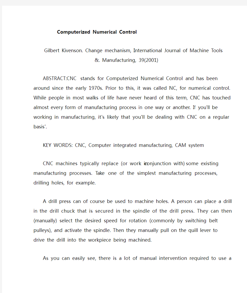
By comparison, the CNC equivalent for a drill press (possibly a CNC machining center or CNC drilling & tapping center) can be programmed to perform this operation in a much more automatic fashion. See fig. 1. Everything that the drill press operator was doing manually will now be done by the CNC machine, including: placing the drill in the spindle, activating the spindle, positioning the workpiece under the drill, machining the hole, and turning off the spindle.
fig.1 machining center
How CNC works
As you might already have guessed, everything that an operator would be required to do with conventional machine tools is programmable with CNC machines. Once the machine is setup and running, a CNC machine is quite simple to keep running. In fact CNC operators tend to get quite bored during lengthy production runs because there is so little to do. With some CNC machines, even the workpiece loading process has been automated. Let's look at some of the specific programmable functions.
Motion control
All CNC machine types share this commonality: They all have two or more programmable directions of motion called axes. An axis of motion can be linear (along a straight line) or rotary (along a circular path). One of the first specifications that imply a CNC machine's complexity is how many axes it has. Generally speaking, the more axes, the more complex the machine.
fig 2 coordinate system
The axes of any CNC machine are required for the purpose of causing the motions needed for the manufacturing process. In the drilling example, these (3) axes would position the tool over the hole to be machined (in two axes) and machine the
hole (with the third axis). Axes are named with letters. Common linear axis names are X, Y, and Z. Common rotary axis names are A, B, and C. These are related to the coordinate system. See fig.2.
Programmable accessories
A CNC machine wouldn't be very helpful if all it could only move the workpiece in two or more axes. Almost all CNC machines are programmable in several other ways. The specific CNC machine type has a lot to do with its appropriate programmable accessories. Again, any required function will be programmable on full-blown CNC machine tools.
Automatic tool changer
Most machining centers can hold many tools in a tool magazine. When required, the required tool can be automatically placed in the spindle for machining.
Spindle speed and activation
The spindle speed (in revolutions per minute) can be easily specified and the spindle can be turned on in a forward or reverse direction. It can also, of course, be turned off.
Coolant
Many machining operations require coolant for lubrication and cooling purposes. Coolant can be turned on and off from within the machine cycle.
The CNC program
Think of giving any series of step-by-step instructions. A CNC program is nothing more than another kind of instruction set. It's written in sentence-like format and the control will execute it in sequential order, step by step.
A special series of CNC words are used to communicate what the machine is intended to do. CNC words begin with letter addresses (like F for feedrate, S for spindle speed, and X, Y & Z for axis motion). When placed together in a logical method, a group of CNC words make up a command that resemble a sentence.
The CNC control
The CNC control (refer to fig.3) will interpret a CNC program and activate the series of commands in sequential order. As it reads the program, the CNC control will activate the appropriate machine functions, cause axis motion, and in general, follow the instructions given in the program.
fig. 3 CNC control
Along with interpreting the CNC program, the CNC control has several other purposes. All current model CNC controls allow programs to be modified (edited) if mistakes are found. The CNC control allows special verification functions (like dry run) to confirm the correctness of the CNC program. The CNC control allows certain important operator inputs to be specified separate from the program, like tool length values6. In general, the CNC control allows all functions of the machine to be manipulated.
Computer integrated manufacturing
Present and future trends of modern manufacture point toward an increase in the use of computers and a decrease in manual methods1. The driving force in this trend is the need to utilize a central computer for storing and retrieving information. Information stored in the central computer is said to reside in a common database. Computer integrated manufacturing (CIM) is a system whereby all aspects of a company's operation are computerized and tied to a common database2. An important element of CIM is CAD/CAM and DNC. A CIM system unifies business, engineering, process planning, inventory, manufacturing, and postproduction.
When fully implemented, CIM will offer the following advantages:
Increased integration and coordination of all company disciplines
Increased productivity
Decreased costs of operation
Improved quality
Reduced scrap
Reduced inventory
Around-the-clock operation with a minimum of operator intervention
CIM also poses the following challenges:
Substantial installation and start-up costs
Training personnel in the use of CIM equipment (hardware and software)
Dealing with proprietary systems and software
Maintaining system hardware and software
Implementing CIM fully in order to make it cost effective
Operating a CIM installation for long periods offline
Planning CIM operations
CIM should be looked upon as ongoing development. Smaller shops are beginning to put together some of its components such as CAD/CAM and computerized accounting. Larger corporations have made substantial gains in adding many more components and some have even achieved full CIM implementation.
Operational strategies within CIM
Many types of strategies have been formulated to increase the efficiency of operations within CIM. Chief among them are group technology (GT) and just-in-time (JIT).
What is a CAM system?
For simple applications (like drilling holes), the CNC program can be developed manually. That is, a programmer will sit down to write the program armed
only with pencil, paper, and calculator. Again, for simple applications, this may be the very best way to develop CNC programs.
As applications get more complicated, and especially when new programs are required on a regular basis, writing programs manually becomes much more difficult. To simplify the programming process, a computer aided manufacturing (CAM) system can be used. A CAM system is a software program that runs on a computer (commonly a PC) that helps the CNC programmer with the programming process. Generally speaking, a CAM system will take the tediousness and drudgery out of programming.
In many companies the CAM system will work with the computer aided design (CAD) drawing developed by the company's design engineering department. This eliminates the need for redefining the workpiece configuration to the CAM system. The CNC programmer will simply specify the machining operations to be performed and the CAM system will create the CNC program (much like the manual programmer would have written) automatically.
What is a DNC system?
Once the program is developed (either manually or with a CAM system), it must be loaded into the CNC control. Though the setup person could type the program right into the control, this would be like using the CNC machine as a very expensive typewriter. If the CNC program is developed with the help of a CAM system, then it is already in the form of a text file. If the program is written manually, it can be typed into any computer using a common word processor (though most companies use a special CNC text editor for this purpose). Either way, the program is in the form of a text file that can be transferred right into the CNC machine. A distributive numerical control (DNC) system is used for this purpose.
A DNC system is nothing more than a computer that is networked with one or more CNC machines. Until only recently, rather crude serial communications protocol (RS-232C) had to be used for transferring programs. Newer controls have more current communications capabilities and can be networked in more conventional ways (Ethernet, etc.). Regardless of methods, the CNC program must of course be loaded into the CNC machine before it can be run.
A CNC user MUST understand the makeup of the CNC machine tool being utilized.
Basic machining practice - the key to success with any CNC machine
Many forms of CNC machines are designed to enhance or replace what is currently being done with more conventional machines. The first goal of any CNC beginner should be to understand the basic machining practice that goes into using the CNC machine tool. The more the beginning CNC user knows about basic machining practice, the easier it will be to adapt to CNC1.
Think of it this way. If you already know basic machining practice as it relates to the CNC machine you will be working with, you already know what it is you want the machine to do. It will be a relatively simple matter of learning how to tell the CNC machine what it is you want it to do (learning to program). This is why machinists make the best CNC programmers, operators, and setup personnel. Machinists already
know what it is the machine will be doing. It will be a relatively simple matter of adapting what they already know to the CNC machine.
For example, a beginner to CNC turning centers (as shown in fig.4) should understand the basic machining practice related to turning operations like rough and finish turning, rough and finish boring, grooving, threading, and necking. Since this form of CNC machine can perform multiple operations in a single program (as many CNC machines can), the beginner should also know the basics of how to process workpieces machined by turning so a sequence of machining operations can be developed for workpieces to be machined.
This point cannot be overstressed. Trying to learn about a particular CNC machine without understanding the basic machining practice related to the machine would be like trying to learn how to fly an airplane without understanding the basics of aerodynamics and flight. Just as a beginning pilot will be in for a great number of problems without understanding aerodynamics, so is the beginning CNC user have difficulty learning how to utilize CNC equipment without an understanding of basic machining practice.
fig.4 CNC turning center
Learning about a new CNC machine - the key points
From a programmer's standpoint, as you begin to learn about any new CNC machine, you should concentrate on four basic areas. First, you should understand the machine's most basic components. Second, you should become comfortable with your machine's directions of motion (axes). Third, you should become familiar with any accessories equipped with the machine. And fourth, you should find out what programmable functions are included with the machine and learn how they are programmed.
Machine components
While you do not have to be a machine designer to work with CNC equipment, it is important to know how your CNC machine is constructed. Understanding your machine's construction will help you to gauge the limits of what is possible with your machine. Just as the race car driver should understand the basics of suspension systems, braking systems, and the workings of internal combustion engines (among other things) in order to get the most out of a given car, so must the CNC programmer understand the basic workings of the CNC machine in order to get the most from the CNC machine tool.
fig.5 universal style slant bed turning center
For a universal style slant bed turning center (as shown in fig.5), for example, the programmer should know the most basic machine components, including bed, way system, headstock & spindle, turret construction, tailstock, and work holding device. Information regarding the machine's construction including assembly drawings is usually published right in the machine tool builder's manual. As you read the machine tool builder's manual, here are some of the machine capacity and construction questions to which you should find answers.
What is the machine's maximum RPM?
How many spindle ranges does the machine have (and what are the cut-off points for each range?
What is the spindle and axis drive motor horsepower?
What is the maximum travel distance in each axis?
How many tools can the machine hold?
What way construction does the machine incorporate (usually square ways, dovetail, and/or linear bearing ways)?
What is the machine's rapid rate (fastest traverse rate)?
What is the machine's fastest cutting feedrate?
These are but a few of the questions you should be asking yourself as you begin working with any new CNC machine. Truly, the more you know about your machine's capacity and construction, the easier it will be to get comfortable with the machine.
Directions of motion (axes)
The CNC programmer MUST know the programmable motion directions (axes) available for the CNC machine tool. The axes names will vary from one machine tool type to the next. They are always referred to with a letter address. Common axis names are X, Y, Z, U, V, and W for linear axes and A, B, and C for rotary axes. However, the beginning programmer should confirm these axis designations and directions (plus and minus) in the machine tool builder's manual since not all machine
tool builders conform to the axis names we show.
The reference point for each axis
Most CNC machines utilize a very accurate position along each axis as a starting point or reference point for the axis. Some control manufacturers call this position the zero return position. Others call it the grid zero position. Yet others call it the home position. Regardless of what it is called, the reference position is required by many controls to give the control an accurate point of reference. CNC controls that utilize a reference point for each axis require that the machine be manually sent to its reference point in each axis as part of the power up procedure. Once this is completed, the control will be in sync with the machine's position.
Accessories to the machine
The third area a beginning CNC user should address is related to other possible additions to the basic machine tool itself5. Many CNC machine tools are equipped with accessories designed to enhance what the basic machine tool can do. Some of these accessories may be made and supported by the machine tool builder. These accessories should be well documented in the machine tool builder's manual. Other accessories may be made by an after-market manufacturer, in which case a separate manual may be involved.
Examples of CNC accessories include probing systems, tool length measuring devices, post process gagging systems, automatic pallet changers, adaptive control systems, bar feeders for turning centers, live tooling and C axis for turning centers, and automation systems. Truly, the list of potential accessory devices goes on and on.
Programmable functions
The programmer must also know what functions of the CNC machine are programmable (as well as the commands related to programmable functions). With low cost CNC equipment, often times many machine functions must be manually activated. With some CNC milling machines, for example, about the only programmable function is axis motion. Just about everything else may have to be activated by the operator. With this type of machine, the spindle speed and direction, coolant and tool changes may have to be activated manually by the operator.
With full-blown CNC equipment, on the other hand, almost everything is programmable and the operator may only be required to load and remove workpieces. Once the cycle is activated, the operator may be freed to do other company functions.
Reference the machine tool builder's manual to find out what functions of your machine are programmable. To give you some examples of how many programmable functions are handled, here is a list a few of the most common programmable functions along with their related programming words.
Spindle control
An "S" word is used to specify the spindle speed (in RPM for machining centers). An M03 is used to turn the spindle on in a clockwise (forward) manner. M04 turns the spindle on in a counter clockwise manner. M05 turns the spindle off. Note that turning centers also have a feature called constant surface speed which allows spindle speed to also be specified in surface feet per minute (or meters per minute).
Automatic tool changer (machining center)
See fig.6. A "T" word is used to tell the machine which tool station is to be placed in the spindle. On most machines, an M06 tells the machine to actually make the tool change. A four digit "T" word is used to command tool changes on most turning centers. The first two digits of the T word specify the turret station number and the second two digits specify the offset number to be used with the tool. T0101, for example, specifies tool station number one with offset number one.
Coolant control
M08 is used to turn on flood coolant. If available, M07 is used to turn on mist coolant. M09 turns off the coolant.
Automatic pallet changer
See fig.7. An M60 command is commonly used to make pallet changes.
fig.6 automatic tool changer fig.7 machining center with APC
Other programmable features to look into
As stated, programmable functions will vary dramatically from one machine to the next. The actual programming commands needed will also vary from builder to builder6. Be sure to check the M codes list (miscellaneous functions) given in the machine tool builder's manual to find out more about what other functions may be programmable on your particular machine. M codes are commonly used by the machine tool builder to give the user programmable ON/OFF switches for machine functions. In any case, you must know what you have available for activating within your CNC programs.
For turning centers, for example, you may find that the tailstock and tailstock quill is programmable. The chuck jaw open and close may be programmable. If the machine has more than one spindle range, commonly the spindle range selection is programmable. And if the machine has a bar feeder, it will be programmable. You may even find that your machine's chip conveyor can be turned on and off through programmed commands. All of this, of course, is important information to the CNC programmer.
R e f e r e n c e s:
[1] Gilbert Kivenson. The Art and Science of Inventing(2nd). NY:VNR Co., 2002
[2] Nikravesh P E. Computer-aided analysis of mechanical systems. Prentice-Hall Inc, 1998
[3] D. A. Bradly, D.Dawson, N.C.Burd, A.J.Loader. Mechatronics: Electronies in products and processes. Champman and Hall, 2001
[4] Plaster H J. Blast Cleaning and Allied Processes, London: Industrial Newspapers Limited, 1999
[5] Crane F A A, Charles J A. Sellection and Use of Engineering Materials. London: Butterworths, 2004
[6] Shigley J E. Mechanical Engineering Design. New York:McGraw-Hill, 1998
[7] Gleason Works, Bevel & Hypoid Gear Design Handbook, 2001
[8] Ananthasuresh, G. K. and Kota, S.,“ Designing Compliant Mechanisms,” Mech. Engrg., Nov. 1995,
pp.93- 96.
[9] Moulton, T. and Ananthasuresh,G. K.,“ Design and Manufacture of Electro-Thermal- Compliant Micro
Devices,” Sensors and Actuators, Physical, 90( 2001), pp.38- 48.
[10] Conry,T. F. and Seireg, A.,“ A M athematical Programming Method for Design of Elastic
Bodies in
Contact,” ASME Jorunal of Applied Mechanics, 2( 1971), pp.387- 392.
[11] Haug,E. J. and Kwak,B. M.,“ Contact Stress Minimization by Contour Design,” Intl. J. Num.
Meth.
Engrg., 12( 1978), pp.917- 930.
[12] Didenko,N. I.,“ Optimal Distribution of Bending Stiffness of an Elastic, Freely Supported
Plate,”
Mech. Solids.( MTT), 16( 1981), pp.133- 143.
[13] Hilding, D., Klarbring, A., and Petersson, J.,“ Optimization of Structures in Unilateral
Co ntact,” Appl.
Mech. Rev.,52( 4)( 1999), pp.139- 160.
[14] Klarbring, A. and Ronqvist, M.,“ Nested Approach to Structural Optimization in Nonsmooth
Mechanics,” Structural Optimization, 10( 1995), pp.79- 86.
[15] Mankame,N. D. and Ananthasuresh,G. K.,“ A Novel Compliant Mechanism for Converting Reciprocating Translation into Enclosing Closed Paths,” submitted to the ASME Journal of Mechanical
Design,( March 2003).