A Compact UWB Antenna for On-Body Applications
A Compact UW
B Antenna for On-Body Applications Nacer Chahat,Student Member,IEEE,Maxim Zhadobov,Member,IEEE,Ronan Sauleau,Senior Member,IEEE,
and Koichi Ito,Fellow,IEEE
Abstract—A new compact planar ultrawideband(UWB)
antenna designed for on-body communications is presented.
The antenna is characterized in free space,on a homogeneous phantom modeling a human arm,and on a realistic high-resolu-
tion whole-body voxel model.In all con?gurations it demonstrates
very satisfactory features for on-body propagation.The results are
presented in terms of return loss,radiation pattern,ef?ciency,and E-?eld distribution.The antenna shows very good performance within the3–11.2GHz range,and therefore it might be used
successfully for the3.1–10.6GHz IR-UWB systems.The simula-
tion results for the return loss and radiation patterns are in good
agreement with measurements.Finally,a time-domain analysis
over the whole-body voxel model is performed for impulse radio
applications,and transmission scenarios with several antennas
placed on the body are analyzed and compared.
Index Terms—Body-area network(BAN),body-centric wireless
communications,compact antenna,printed antenna,ultrawide-
band(UWB)antenna.
I.I NTRODUCTION
B ODY-AREA NETWORKS(BAN)are wireless commu-
nication systems that enable communications between wearable and/or implanted into the human body electronic devices.Such systems are of great interest for various appli-cations including sport,multimedia,health care,and military applications[1],[2].Ultrawideband(UWB)antennas have been identi?ed as a highly promising solution for BAN.One of the major advantages of the UWB systems at3.1–10.6GHz is their high data-rate-transmission capabilities(typically100 Mbps)with low power spectral densities(41.3dBm/MHz) [3],ensuring thereby low interference with other narrow-band wireless devices.
Designing an antenna for UWB body-centric communica-tions is a challenging task,as the antenna needs to ful?ll several fundamental requirements,such as:1)optimized characteristics in frequency-and time-domains;2)small size and low pro?le;3) good on-body propagation.
Indeed,both frequency-and time-domain responses should be considered and characterized[4]–[7],and the interaction with the human body,i.e.,the changes in the antenna performance
Manuscript received April12,2010;revised August04,2010;accepted September24,2010.Date of publication January28,2011;date of current ver-sion April06,2011.This work was supported in part by the“Agence Nationale de la Recherche”(ANR),France by Grants ANR-09-VERS-003(META VEST project)and ANR-09-RPDOC-003-01(Bio-CEM project),“Région Bretagne”(Dose_ULB project),and in part by the“Centre National de la Recherche Scienti?que”(CNRS),France.
N.Chahat,M.Zhadobov,and R.Sauleau are with the Institute of Electronics and Telecommunications of Rennes(IETR),UMR CNRS6164,University of Rennes1,35042Rennes,France(e-mail:nacer.chahat@univ-rennes1.fr).
K.Ito is with the Graduate School of Engineering,Chiba University,Chiba 263-8522,Japan(e-mail:ito.koichi@faculty.chiba-u.jp).
Digital Object Identi?er10.1109/TAP.2011.2109361due to the presence of the body and power losses in the tissues, should be carefully taken into account[8].
Besides,the miniaturization of UWB antennas is particu-larly important for wearable applications.Signi?cant research efforts have been undertaken to reduce the size of the radiating structures,and some interesting miniaturization techniques have been proposed[9]–[11].
Finally,for on-body applications,the antenna needs to ex-hibit suitable on-body propagation features.However,in most of the proposed body-centric UWB communication scenarios,om-nidirectional planar antennas are placed parallel to the human body,and,as a result,the ef?ciency of these antennas is signi?-cantly reduced[12],and the on-body propagation is not optimal. Indeed,this con?guration is more suitable for off-body commu-nication,i.e.,for communication between an antenna mounted on the body and a remote device or base station,as demonstrated in several studies introducing textile antennas with high poten-tial for off-body communications[13]–[15].It was shown that the antenna-?eld polarization needs to be normal to the body surface in order to improve the on-body propagation[16].In par-ticular,it was demonstrated that a quarter-wavelength monopole antenna is appropriate for on-body communication for the fol-lowing reasons:1)it has an omnidirectional pattern with max-imum radiation along the body surface;2)-?eld is normal to the body surface[16].Furthermore,a comparison between two different UWB antennas has been performed showing that the planar inverted cone antenna(PICA)with an omnidirec-tional monopole-like pattern demonstrates very good perfor-mances for on-body communications[17].Nevertheless,the quarter-wavelength monopole antenna and the PICA have a rel-atively large ground plane and heights.
To overcome this problem we introduce here a reduced-size UWB antenna suitable for on-body communications since the -?eld is polarized perpendicularly to the body surface.
This paper is organized as follows.The antenna design and a two-thirds muscle equivalent phantom used for numerical and experimental characterizations are introduced in Section II.The main characteristics of the proposed antenna,namely its re?ec-tion coef?cient,radiation patterns,and ef?ciency are then given in Section III.Experimental results,obtained using the phantom, are also compared to calculations.In addition,the-?eld distri-bution around a homogeneous arm model and whole-body voxel phantom is also studied numerically to investigate the on-body propagation.Finally the time-domain capabilities of the antenna are analyzed in Section IV,transmission scenarios between sev-eral antennas placed on the body are numerically studied,and the effect of modulation schemes on the on-body system perfor-mance is discussed.
All calculations are carried out using the?nite integration technique implemented in CST Microwave Studio.
0018-926X/$26.00?2011IEEE
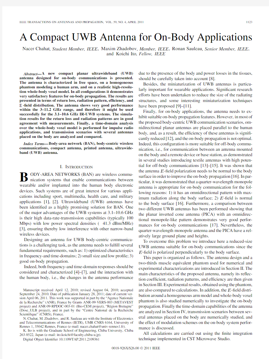
Fig.1.(a)Geometry of the proposed antenna.(b)Antenna on the two-thirds muscle-equivalent phantom.
II.E XPERIMENTAL M ODELS
A.Antenna Design
An antenna was designed and manufactured for UWB
on-body applications.It consists of a compact microstrip-fed printed monopole [Fig.
1(a),]printed on a 1.6-mm-thick AR350
substrate .In this study,the antenna performance is evaluated and optimized in the following con?gurations:1)antenna located on a homogeneous phantom with two-thirds muscle-equivalent dielectric proper-ties;2)antenna mounted on a high-resolution nonhomogeneous human body model (Sections III-C,III-E,and IV).
To our best knowledge,the smallest UWB antennas have a signi?cant height (around 17mm)[18]–[21]and thus might be not suitable for a perpendicular con?guration (-?eld normal to the body).Here,the ground plane
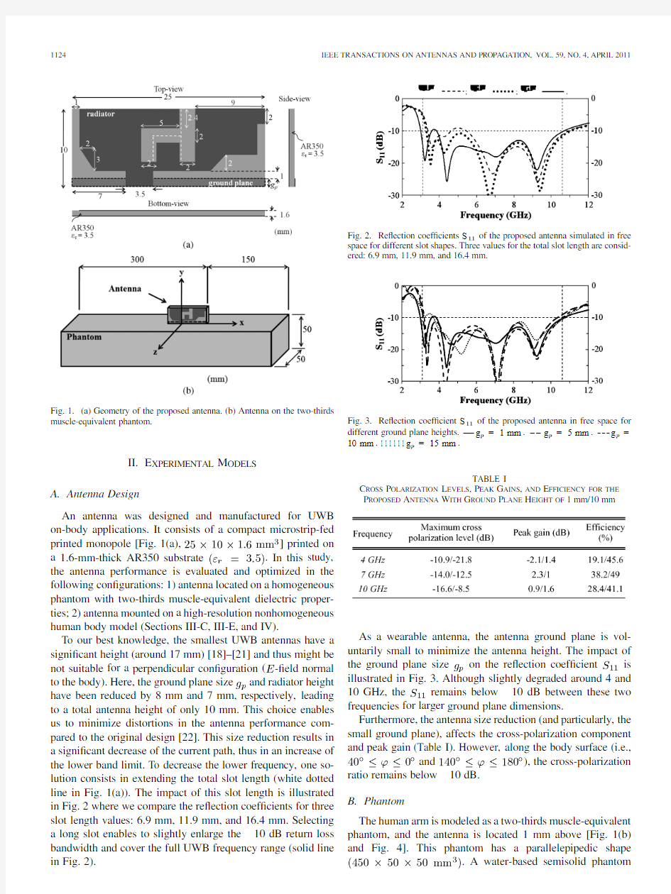
size and radiator height have been reduced by 8mm and 7mm,respectively,leading to a total antenna height of only 10mm.This choice enables us to minimize distortions in the antenna performance com-pared to the original design [22].This size reduction results in a signi?cant decrease of the current path,thus in an increase of the lower band limit.To decrease the lower frequency,one so-lution consists in extending the total slot length (white dotted line in Fig.1(a)).The impact of this slot length is illustrated in Fig.2where we compare the re?ection coef?cients for three slot length values:6.9mm,11.9mm,and 16.4mm.Selecting a long slot enables to slightly enlarge the 10dB return loss bandwidth and cover the full UWB frequency range (solid line in Fig.
2).
Fig.2.Re?ection coef?cients S of the proposed antenna simulated in free space for different slot shapes.Three values for the total slot length are consid-ered:6.9mm,11.9mm,and 16.4
mm.
Fig.3.Re?ection coef?cient S of the proposed antenna in free space for different ground plane heights.g =1mm .g =5mm .g =
10mm .111111g =15mm .
TABLE I
C ROSS P OLARIZATION L EVELS ,P EAK G AINS ,AN
D
E FFICIENCY FOR THE P ROPOSED A NTENNA W ITH G ROUND P LANE H EIGHT O
F 1mm/10
mm
As a wearable antenna,the antenna ground plane is vol-untarily small to minimize the antenna height.The impact of the ground plane
size on the re?ection
coef?cient is illustrated in Fig.3.Although slightly degraded around 4and
10GHz,
the
remains below 10dB between these two frequencies for larger ground plane dimensions.
Furthermore,the antenna size reduction (and particularly,the small ground plane),affects the cross-polarization component and peak gain (Table I).However,along the body surface
(i.e.,
and ),the cross-polarization
ratio remains below 10dB.B.Phantom
The human arm is modeled as a two-thirds muscle-equivalent phantom,and the antenna is located 1mm above [Fig.1(b)and Fig.4].This phantom has a parallelepipedic
shape
.A water-based semisolid phantom
CHAHAT et al.:COMPACT UWB ANTENNA FOR ON-BODY APPLICATIONS
1125
Fig. 4.Antenna prototype mounted on the two-thirds muscle-equivalent phantom.
[23]was chosen as a tissue-equivalent model for UWB mea-surements.The complex permittivity and conductivity of the
phantom are adjusted using the polyethylene powder and sodium chloride,respectively.Agar is used to maintain the shape of the phantom,sodium azide is a preservative,and TX-151improves the phantom stickiness [23].
III.F REQUENCY -D OMAIN A NALYSIS
In this section,the dielectric properties of the phantom are provided in the 3–11GHz range.Then computational and mea-sured results are presented for the antenna return loss and radia-tion pattern.Finally,-?eld distributions are computed for the arm and human body models.
A.Numerical Model and Dielectric Properties of the Phantom in the UWB Band
In order to model accurately the antenna in presence of the phantom,the dielectric properties of the phantom should be de-termined carefully in the 3.1–10.6GHz range.Two-thirds of the muscle permittivity was used as a target value for the phantom.The muscle dielectric properties are well characterized up to 20GHz [24].For the numerical modeling,the complex dielectric
permittivity of the phantom is expressed as a Debye’s disper-sion equation
[25]
(1)
where is the angular
frequency,is the static
permittivity,is the optical permittivity,
and is the relaxation time.The best ?t of this theoretical model to the target values was obtained
for
,,
and .Theoretical
permittivity and conductivity model is in a very good agree-ment with target values over the considered frequency range (3–11GHz),con?rming thereby that the choice of the Debye model is appropriate (Fig.5).The phantom has been built as explained in Section II-B and characterized using the dielectric probe kit 85070E (Agilent Tech.,CA).The measured complex permittivity is in satisfactory agreement with the numerical re-sults (Fig.5).
B.Re?ection Coef?cient and Impact of the Feed Connector The re?ection
coef?cients
of the proposed UWB an-tenna are represented in Fig.6assuming the antenna is either in free space or on the arm.Here,the numerical models do not take into account the feed connector.These results show
that
the
is very slightly affected by the presence of
the Fig.5.Measured and computed characteristics of the phantom.Target.
Measurement.
Calculation.
Fig.6.Simulated re?ection coef?cients of the optimized antenna (the total slot
length equals 16.4mm).
Antenna in free space.Antenna mounted on the
phantom.
Fig.7.Re?ection coef?cient of the antenna with feed connector mounted on
the phantom.
Simulation results. Measurements.phantom and remains below 10dB within the 3–11.3GHz
range.The fabricated prototype is fed by a tiny coaxial probe connector (BL58-3123-00,Orient Microwave Corp.,Japan).Its re?ection coef?cient measured for the antenna mounted on the phantom is represented in Fig.7.The agreement with simulations (accounting this time for the feed connector)is very satisfactory.The 10dB return loss bandwidth almost covers the full 3.1–10.6GHz UWB frequency range.C.Radiation Patterns
The antenna radiation patterns
in
and planes have been computed at three frequency points
(4,7,and 10GHz)for three con?gurations:antenna alone,an-tenna on the phantom,and antenna on the whole-body model (Duke model from Virtual Family [26]).Duke represents a 34year-old 174cm-tall adult weighting https://www.360docs.net/doc/fe11150519.html,pared to the free-space scenario,the antenna mounted on the phantom shows
1126IEEE TRANSACTIONS ON ANTENNAS AND PROPAGATION,VOL.59,NO.4,APRIL
2011
Fig.8.Measured and simulated radiation patterns at 4,7,and 10GHz.(a) =90.(b)'=0.Free space.On homogeneous phantom.On
voxel phantom.
Measurement.
TABLE II
P EAK AND A VERAGE G AINS OF THE A NTENNA IN F REE S PACE AND ON
THE P
HANTOM
better front-to-back ratio.This is essentially related to the ab-sorption in and re?ections from the phantom.In addition,com-parison with measurements at 4and 10GHz in
the
and planes using the two-thirds muscle-equivalent phantom con?rms the very satisfactory matching between experimental and numerical results.The average and peak values of the an-tenna gain are given in Table II.These data con?rm the gain
reduction
in
plane due to the presence of the phantom,as already mentioned in other studies (e.g.[27],[28]).However,
in
plane,the gain is reduced at 4GHz where absorptions are higher,and at 7and 10GHz,the gain increases due to the re?ection caused by the arm.D.Radiation Ef?ciency
Radiation ef?ciencies of 19.1%,38.2%,and 28.4%are es-timated on the homogeneous phantom,at 4,7,and 10GHz,respectively.As expected,the radiation ef?ciency is quite low since the gap between the antenna and the body is set to 1mm,
which corresponds to a practical situation where the antenna is mounted on clothes.However,the antenna ef?ciency can be im-proved using a larger ground plane size as shown in Table https://www.360docs.net/doc/fe11150519.html,puted E-Field Distributions
To estimate possible range of application scenarios for the proposed antenna,it is important to consider electromagnetic ?eld distribution in,on,and around the body.
Fig.9shows the computed electric ?eld distributions in the
cross-section plane of the numerical arm model
[
plane in Fig.1(b)]at 4,7,and 10GHz.It is important to highlight that,
in this con?guration,
the
component is the dominant one,which means that the major contribution to the overall electric ?eld comes from the component perpendicular to the upper side of the phantom.
Based on these results,several observations can be made:?The electromagnetic ?eld propagates along the phantom surface and,as expected,attenuates nonlinearly;
?Within the considered frequency range,higher frequencies correspond to the more localized energy absorption.
The ?eld propagation around the body is analyzed in Fig.10using Duke model (the spatial resolution
is ).The antenna is mounted on the left arm where most part of the electric ?eld is con?ned.Fig.10shows that the electromagnetic ?eld propagates in both directions along the left arm and that shadowing due to the human body plays a key role since the electric ?eld is much stronger at the source side compared to the opposite side (the attenuation is at least 70dB).Therefore,communications between antennas situated on opposite sides of the body might be dif?cult in this con?guration.However,wire-less radio links between hand/head or hand/foot are absolutely
CHAHAT et al.:COMPACT UWB ANTENNA FOR ON-BODY APPLICATIONS
1127
Fig.9.Electric ?eld distributions (root-sum-square)in x 0y cross section of a homogeneous
model.
Fig.10.Electric ?eld distribution around and within the Duke model at 4,7,and 10GHz.
achievable,and the time-domain behavior for such communica-tion scenarios is studied in Section IV.
IV .P ROPAGATION A ROUND THE B ODY
A.Time-Domain Analysis
A UW
B system can be either a traditional pulse-based system transmitting each pulse that occupies the entire UWB bandwidth,or a carrier system such as,for instance,multiband orthogonal frequency-division multiplexing (MB-OFDM)which has been adopted by WiMedia.Time-domain analyses
are of great importance to evaluate the capabilities of UWB an-tennas for impulse radio systems (IR-UWB).A UWB antenna excited by nanosecond pulses behaves as a pulse-shaping ?lter.Therefore,a suitable antenna for UWB communications has to demonstrate minimum distortion of the pulse in time-domain to reduce the complexity of the detection mechanisms at the re-ceiver terminal.The quality of the received pulse is determined
by
(2)
1128IEEE TRANSACTIONS ON ANTENNAS AND PROPAGATION,VOL.59,NO.4,APRIL
2011
Fig.11.(a)Normalized excitation signal.(b)Its spectral
density.
Fig.12.Locations of the probes around the antenna.
where the source
pulse and received
pulse are normalized by their respective energies.
The source pulse signal chosen here [Fig.11(a)]is a ?fth-order derivative Gaussian pulse satisfying the FCC power mask [Fig.
11(b)]
(3)
where
and denote the amplitude and spread of the Gaussian pulse,respectively.
In the numerical simulations,the output signal is monitored in three
directions
using three probes located 50cm
apart from the antenna (Fig.12).The pulse received at each
probe is represented in Fig.13(a).Its
?delity
is excellent:98.8%,98.3%,and 95.2%for probes A,B,and C,respectively.A similar study has been conducted for on-body propagation.To this end,three transmission scenarios between four antennas are considered:the transmitting antenna is mounted on the
left
Fig.13.(a)Signals monitored by virtual probes.(b)Their spectra.
wrist (TX1),the three receiving antennas are placed on the left arm (RX1),left ear (RX2),and left leg (RX3)(Fig.14).The dis-tortion of the received pulses (Fig.15)depends on the antenna position,and their ?delity equals 75%,46%,and 81%,for RX1,RX2,and RX3,respectively.
The most pronounced distortion is observed for the antenna on the head,suggesting that a direct communication in this sce-nario might be delicate.
From these results,it is clear that pulses experience strong distortions in on-body scenarios.The signal ?delity can be very low (e.g.,46%for RX2),and therefore an appropriate mod-ulation scheme needs to be implemented.For instance binary phase-shift keying (BPSK)is not appropriate in this case be-cause of strong distortions of the transmitted signal.
However,in IR-UWB systems,pulse-position modulation (PPM)and on-off keying (OOK)are excellent candidates for on-body communications.These two modulation schemes can be implemented with noncoherent receivers using energy de-tection mechanisms instead of correlation for coherent systems.With a noncoherent receiver,the pulse shape is secondary and the low ?delity can be overcome.
We focus our attention here on IR-UWB system using the en-tire UWB-band.However,these modulations schemes can also be used as multiband schemes [29],[30].
CHAHAT et al.:COMPACT UWB ANTENNA FOR ON-BODY APPLICATIONS
1129
Fig.14.Transmission scenario with four antennas mounted on the
body.
Fig.15.Wave forms of the received pulses.
B.On-Body Propagation
As a non-coherent receiver is preferred,the path loss needs to be investigated.The path loss of the proposed antenna mounted on the homogeneous phantom with two different ground plane heights is presented in Fig.16.For each distance,each point represents the path loss result at one frequency point.The an-tenna with a 10-mm-height ground plane demonstrates a better on-body propagation https://www.360docs.net/doc/fe11150519.html,ing a larger ground plane improves the path loss by 7dB whereas the cross-polarization component remains fairly the same between these two antenna models.However a larger ground plane improves the
antenna
Fig.16.Path loss of the proposed antenna mounted on the homoge-neous phantom with different ground plane heights.222g =1mm . g =10mm .
TABLE III
M EAN P ATH G AIN AND P ATH G AIN V ARIABILITY (R ANGE )FOR S OME S PECIFIC
ON B ODY P ATH L
OSS
ef?ciency (Table I)and as consequences the path loss becomes higher.
The propagation path loss for this on-body scenario is pre-sented in Table III.The mean path gain and variability within the 3.1–10.6GHz UWB band are given for all receiving an-tennas.The wrist-to-arm link,being the shortest,has the lower loss,with an average loss of 53.9dB,and has a peak-to-peak variation of approximately 32.9dB within the whole UWB fre-quency band.The wrist-to-head link has the higher average loss,(this is mainly due to the longer link length),and its path loss variability is estimated around 34.4dB.In the wrist-to-calf link,an average loss of 60.5dB is evaluated,and the variability is much lower compared to the other links.
V .C ONCLUSION
A compact planar UW
B monopole antenna has been de-signed for on-body communications.The antenna shows good impedance matching and satisfactory on-body propagation fea-tures.It was shown that,in spite of the small distance between the antenna and the body,the latter does not affect signi?cantly the antenna input matching.The re?ection coef?cient and ra-diation patterns were successfully measured using a two-thirds muscle homogeneous phantom.
The electric ?eld distributions around a realistic whole-body model have been computed at different frequencies,and suitable on-body propagation features have been highlighted.
Compared to the parallel con?guration,the perpendicular one demonstrates higher gain,better on-body propagation,and the antenna impedance performance is less affected.
The time-domain behavior of the proposed antenna has been fully investigated on a realistic body model.Signi?cant pulse distortions have been observed and thus a noncoherent modulation is advised for on-body communication.Hence,for
UWB定位系统行业应用解决方案(最新版)
UWB定位系统行业应用解决方案 一、工厂仓库 应用背景: 现代制造业生产设备繁多,生产车间广阔,生产工人数量多。 UWB智能化定位系统可帮助实现: 1)生产工程的安全管理,进一步提高生产效率,突破生产瓶颈;2)对员工的智能化管理及生产设备的维护。 产品形态如下图所示: 部署方案 系统功能: 1)减少人工考勤工作量,提高员工出勤率; 2)提高物资、设备的利用效率,减少人工管理成本; 3)特殊区域限制人员进出及人员滞留时间,实现安全管理; 4)设备自动报修,杜绝漏检; 5)实时显示人员动态信息,实现人员动态管理;
6)及时响应特殊情况,保障员工安全。 二.司法/监狱 应用背景: 监狱当前的监管手段存在以下问题: 1.不能掌握人员的实时位置; 2.人工点名费时费力; 3.违规使用手机或其它通信工具的情况; 4.管理融合性差,对突发事件响应能力差等等。 使用UWB监狱定位系统,可有效解决: 1.弥补管理漏洞、降低监管执法风险(如:预防非正常死亡); 2.解放警力、降低成本、提高工作效率; 3.变被动监管为主动监管,达到事前预防、事中管控、事后查证管理新思路; 4.提升监管工作智能感知,立体防控、快速处置与精准服务能力。 产品形态如下图所示: 部署方案:
系统功能: 1)主动预警,民警遇袭或与突发事件时求助告警,确保民警的人身安全,解决事故发生滞后性问题,将事故隐患提前暴露,避免事故发生; 2)突发现场再现,物联网技术与现有视频结合,可以实时查看事故发生的现场情况,为调配相关警力解决突发事件提供依据; 3)解放警力降低监管、执法风险,减轻工作压力、节约看管成本、实时点名,在押人员位置信息实时在线,行动轨迹跟踪、回放,大大降低了民警的工作强度,有效提高工作效率; 4)在关键出入口及周界布置禁入边界,在押人员靠近、非法进入主动告警,降低监管执法的风险。 三.医院/养老院 应用背景: 排队3小时就医3分钟,这是当前典型的就医现象。患者的大部分时间可能浪费在停车场排队、寻找科室、挂号排队,有时候做完检查后挂号专家已经下班,需要改天再来。 为节省患者时间,提高就医效率,可以采用UWB定位养老院定位系统: 1.提供定位导航、人员管理、物资监管、新生儿实时监控、应急救援等功能; 2.解决移动查房、移动护理、新生儿监管、医疗设备监管、物资监管等。 产品形态如下图所示: 部署方案:
最详细的UWB定位技术介绍
最详细的U W B定位技 术介绍 -CAL-FENGHAI-(2020YEAR-YICAI)_JINGBIAN
超宽带(UWB)是一种无线技术,可以在短时间内以极低功率实现数据的高速传播。超宽带有很多独特的技术特性,是具有极强竞争优势的短距无线传输技术。但该技术在2002年之后才正式被大家关注,主要是该技术之前只能在军方使用,2002年2月,美国联邦通信委员会才正式批准可以用于民用。 UWB超宽带技术是一种无线载波通信技术,占有很宽的频谱范围,按照FCC的规定,从到之间的的带宽频率为UWB所使用的频率范围。并且数据传输是依靠纳秒级的非正弦波窄脉冲,适用于高速、近距离的无线个人通信。 UWB是一种“特立独行”的无线通信技术,它将会为无线局域网LAN和个人局域网PAN的接口卡和接人技术带来低功耗、高带宽并且相对简单的无线通信技术。 1)抗干扰性能强 UWB采用跳时扩频信号,系统具有较大的处理增益,在发射时将微弱的无线电脉冲信号分散在宽阔的频带中,输出功率甚至低于普通设备产生的噪声。接收时将信号能量还原出来,在解扩过程中产生扩频增益。因此,与IEEE 、IEEE 和蓝牙相比,在同等码速条件下,UWB具有更强的抗干扰性。 2)传输速率高 超宽带数据速率可以达到几十Mbit/s到几百Mbit/s。有望高于蓝牙100倍,也可以高于IEEE 和。 3)带宽极宽 UWB使用的带宽在1GHz以上,高达几个GHz。超宽带系统容量大,并且可以和目前的窄带通信系统同时工作而互不干扰。这在频率资源日益紧张的今天。开辟了一种新的时域无线电资源。 4)消耗电能小 通常情况下,无线通信系统在通信时需要连续发射载波,因此,要消耗一定电能。而UWB不使用载波。只是发出瞬间脉冲电波,也就是直接按0和1发送出去,并且在需要时才发送脉冲电波,所以消耗电能小。 5)保密性好
uwb室内定位系统详解
uwb室内定位系统详解 室内定位是物联网的基础服务之一,根据应用场景不同,可以促进企业的运作和营销效率提升,或为消费端用户提供更加便捷的体验。 目前而言室内定位根据服务对象和网络构架的不同,室内定位市场可以分为专用场地应用和通用场地应用两大类,并构成不同的商业模式。 室内定位安全管理系统由硬件定位设备、定位引擎和应用软件构成。系统采用UWB定位技术,通过TDOA到达时间差的算法实现三维定位,定位精度优于30cm,单区域支持多于1000张/秒的定位标签,精度高,容量大。 高精度室内定位系统应用软件支持PC端和移动端访问,并提供位置实时显示、历史轨迹回放、人员考勤、电子围栏、行为分析、多卡判断、智能巡检等功能。主要应用场景有:工厂人员/物资定位、监狱犯人定位、养老院老人定位、隧道/管廊施工人员定位、发电站定位。 室内定位系统架构: 应用层 通过解算层获取位置、人脸对比结果和视频联动视频流数据,以地图的形式实时显示个标签的位置和标签的携带者,并可以选择显示视频联动的监控画面。 服务层 服务层包括定位引擎软件、系统管理软件、对内和对外接口软件组成,这些
软件部署在系统服务器。 网络层 网络层分为局域网,提供数据传输通道。 传输层 传输层也称主干通信网(简称“主干网”),是定位基站、人脸识别和视频联动摄像头(设备)与解算层、应用层之间的数据传输通道,可以选择有线或者无线传输方式。 感知层 设备层主要包括定位基站和标签、人脸识别和视频联动摄像头。通过定位基站与定位标签的UWB定位信道实现对定位标签的定位,通过通信定位基站与定位标签的ZigBee通信信道实现定位基站对定位标签的参数配置、定位标签的状态回传以及定位标签上下行的数据。 UWB室内定位技术与GPS定位技术比较: 高精度室内定位系统使用精度优于0.3米的UWB定位技术,可以实现人员位置的实时监控和运动轨迹的回放,在巡检以及高危作业中结合相关流程可以实现精准的状态和行为监管。
UWB定位系统概述
超宽带(UWB)是射频应用技术领域的一项重大突破。Ubisense 公司利用该技术构建了革命性的实时定位系统(RTLS),该系统能够在传统的挑战性应用环境中达到较高的定位精度,并具有很好的稳定性;而诸如RFID 、WiFi 的技术并不能完成该类应用。 Ubisense 系统高达15cm 的3D 定位精度,使得用户能够完成一系列的新型应用。例如: 设备的精密时间与空间定位,如在仓库中将货物、设备的位置信息与条形码扫描仪的数据相结合; 在仓库中将叉车放置货物时车叉的位置数据与货盘或垫板的ID 数据结合,实现货盘中货物的定位; 物体间关联信息自动检测,如在无需人工输入情况下,检测出相似于某特别类型的小车或其他模型,并选择正确的程序来驱动这个自动机械工具; 在汽车制造厂最后的质量检测段,进行车辆的识别与定位; 监控紧急状况中雇员是否已经到达指定区域;或决定是否真正缺人并需要外协; Ubisense 系统通常能够在12个月以内快速回收投资,这是因为系统产生的数据能给那些不直观、不真实的复杂工作过程提供一定的透明度;当Ubisense 系统嵌入到生产过程后,它能够为工人提供清晰的位置信息,降低了由人为错误引发的损失,同时也减少了任务的执行时间。这最终使得企业改进了生产品质,并降低了生产成本。 Ubisense 7000系统 系统包含三部分:电池供电的活动标签,能够发射UWB 信号来确定位置;位置固定的传感器,能够接收并估算从标签发送过来的信号;以及综合所有位置信息的软件平台,获取、分析并传输信息给用户和其他相关信息系统。 在该系统中,标签发射极短的UWB 脉冲信号,传感器接收此信号,并采用综合的测量手段来计算标签的位置。由于采用了UWB 技术,加上Ubisense 独特的传感器功能,确保了较高的定位精度和室内应用环境的可靠性,而通常这些室内应用极具挑战性:墙壁和金属物的反射,导致较强的多路径效应。传感器通常按照蜂窝单元(Cell)的形式进行组织,典型的划分方式是矩形单元,附加的传感器根据其几何覆盖区域进行增加;每个定位单元中,主传感器配合其他传感器工作,并与单元内所有检测到位置的标签进行通讯;通过类似于移动通讯网络的蜂窝单元组合,能够做到较大面积区域的覆盖; 标签的位置通过标准以太网线或无线局域网,发送到定位引擎软件;定位引擎软件将数据进行综合,并通过API 接口传输到外部程序或Ubisense 定位平台,实现空间信息的处理以及信息的可视化;由于标签能够在不同定位单元(Cell)之间移动,定位平台能够自动在一个主传感器和下一个主传感器之间实现无缝切换。在建立系统时,需要对整体的多单元空间结构指定3D 参考坐标系。当标签在参考 坐标系内的多个单元中移动时,可视化模块能够实时显示标签位置。 在实际的应用中,有诸多的方法可供选择,以设计出满足应用需求和物理环境的系统。如:定位区域的几何划分,不同区域的定位精度要求,哪些物体附着定位标签,哪一种速度是正常的,期望物体间产生何种的操作与交互行为,哪些是固定或未加标签的物资,电池寿命的需求,供电的方式或以太网通讯的方式,与其他RF 系统的融合,等等。 Ubisense 和授权代理商均提供该系统的相关设计服务。
低成本高精度的定位技术-UWB定位.docx
低成本的高精度定位技术-UWB定位 除了全球定位系统(GPS)在导航和室外环境的应用定位以外,人们对室内定位、短距离定位等应用不甚了解。随着各式各样的建筑的建立人们在室内的时间是室外的4倍,室内定位的需求也越来越大。 未来无线定位技术的趋势是室内定位与室外定位相结合,实现无缝的、精确的定位。现有的网络技术还不能完全满足这个要求,而UWB技术由于功耗低、抗多径效果好、安全性高、系统复杂度低、定位精度极高等优点,在众多无线定位技术中脱颖而出。 UWB定位实现原理: 超宽带(Ultra Wide-Band,UWB)UWB定位是一种新型的无线通信技术。该技术采用TDOA(到达时间差原理),利用UWB技术测得定位标签相对于两个不同定位基站之间无线电信号传播的时间差,从而得出定位标签相对于四组定位基站的距离差。 使用TDOA技术不需要定位标签与定位基站之间进行往复通信,只需要定位标签只发射或只接收UWB信号,故能做到更高的定位动态和定位容量。 UWB定位特点: 1.定位基站之间使用无线同步,减少施工成本 2.网络简单,部署规划成本极低,自恢复能力强 3.可选多种基站定位方式,定位标签续航时间最短超过一个月。具有电量监测效用,定位基站电量不足时及时提醒充电 4.终端实时显示位置信息,实现导航效用,容量无限大 5.可通过移动通信网络实现远程位置跟踪 6.可应用于复杂的工业现场,以最优性价比实现了较好的效果
UWB定位的应用可以为哪些行业带来改变? 工业制造: UWB定位系统可以实时记录显示工人位置信息,实现自动考勤,提高员工出勤率;通过跟踪监测人员、物资、设备,来保障物资及工人的安全、减少人工管理成本。 医院、养老院: 老人或病人,由于生活自理能力差,且自我判断和保护能力不足,容易迷失方向,遇到危险时也很难实现自救和求助。 通过UWB定位技术能够有效对老人和医院病人可以实时的跟踪定位,及时处理应急情况,为他们的生命健康安全和日常生活提供有力保障,同时减轻工作人员的压力。 司法监狱: 监狱安全管理一直是备受关注的问题,通过UWB定位技术如何杜绝监狱犯人管理漏洞、降低监管执法风险呢? 运用UWB定位技术能够很好监管:实时掌握人员的实时位置、人数清点、监狱犯人腕带防拆报警、电子围栏、聚众分析、行动轨迹跟踪、回放、摄像联动警报等,能够很大程度的降低监管执法的风险,防止意外事故的发生。 隧道: 隧道施工过程中作业现场点多面广,安全管控难度大。运用UWB定位可以提供的集风险管控、人员管理、实时显示、应急救援等效用的智慧监
UWB室内定位系统整体解决方案介绍
UWB室内定位系统 页脚内容1
1.公司简介 成都恒高科技有限公司,致力于高精度无线定位技术与视觉图像处理技术,打造两者相结合的“四维高精度定位系统”。该系统包含传统意义的无线电三维空间合作式定位安防,并辅以视觉定位、视频联动的非合作式定位监管。 恒高旨在为客户提供全方位定位安防监管,以保障客户的人员物资安全。恒高结合定位及视觉数据,精准分析企业客户的人员行为,规范人员作业方式。在保障安全的同时,提升作业效率,为客户提供了丰厚的利润价值。 恒高依托电子科技大学前沿科学技术,及自身强劲的工程实践团队,在保证高精度定位系统优异效果的同时,将系统产品定价拉低了一个量级。为客户提供价值,并减小客户的成本投入。恒高现已申请专利技术二十余项,软件著作十余项,并不断有新技术转化为知识产权。 恒高拥有多个行业的系统解决方案,已实施于大型基建工地,石油化工,电力电网,养老院,监狱,并积极跟进智能社区,政府机关,机器人导航,旅游,停车场等等。恒高还在不断挖掘高精度定位系统的潜力,以期为更多行业服务。让每一个位置,每一张图像都发挥价值。 匠心永恒,高山景行。恒高于2014年成立至今,秉持匠心不断打磨产品及系统,力求为客户提供最好的产品、系统和解决方案! 页脚内容2
2.UWB无线定位 2.1系统方案 2.1.1定位概念 2.1.1.1UWB技术原理 超宽带(Ultra Wide-Band,UWB)是一种新型的无线通信技术,根据美国联邦通信委员会的规范,UWB的工作频带为3.1~10.6GHz,系统-10dB带宽与系统中心频率之比大于20%或系统带宽至少为500MHz。UWB信号的发生可通过发射时间极短(如2ns)的窄脉冲(如二次高斯脉冲)通过微分或混频等上变频方式调制到UWB工作频段实现。 超宽带的主要优势有,低功耗、对信道衰落(如多径、非视距等信道)不敏感、抗干扰能力强、不会对同一环境下的其他设备产生干扰、穿透性较强(能在穿透一堵砖墙的环境进行定位),具有很高的定位准确度和定位精度。 页脚内容3
UWB定位系统行业应用解决方案最新版
UWB定位系统行业应用解决方案最新 版
UWB定位系统行业应用解决方案 一、工厂仓库 应用背景: 现代制造业生产设备繁多,生产车间广阔,生产工人数量多。 UWB智能化定位系统可帮助实现: 1)生产工程的安全管理,进一步提高生产效率,突破生产瓶颈; 2)对员工的智能化管理及生产设备的维护。 产品形态如下图所示: 部署方案 系统功能:
1)减少人工考勤工作量,提高员工出勤率; 2)提高物资、设备的利用效率,减少人工管理成本; 3)特殊区域限制人员进出及人员滞留时间,实现安全管理;4)设备自动报修,杜绝漏检; 5)实时显示人员动态信息,实现人员动态管理; 6)及时响应特殊情况,保障员工安全。 二.司法/监狱 应用背景: 监狱当前的监管手段存在以下问题: 1.不能掌握人员的实时位置; 2.人工点名费时费力; 3.违规使用手机或其它通信工具的情况; 4.管理融合性差,对突发事件响应能力差等等。 使用UWB监狱定位系统,可有效解决: 1.弥补管理漏洞、降低监管执法风险(如:预防非正常死亡); 2.解放警力、降低成本、提高工作效率; 3.变被动监管为主动监管,达到事前预防、事中管控、事后查证管理新思路; 4.提升监管工作智能感知,立体防控、快速处理与精准服务能力。 产品形态如下图所示:
部署方案: 系统功能: 1)主动预警,民警遇袭或与突发事件时求助告警,确保民警的人身安全,解决事故发生滞后性问题,将事故隐患提前暴露,避免事故发生; 2)突发现场再现,物联网技术与现有视频结合,能够实时查看事故发生的现场情况,为调配相关警力解决突发事件提供依据; 3)解放警力降低监管、执法风险,减轻工作压力、节约看管成本、实时点名,在押人员位置信息实时在线,行动轨迹跟踪、回放,大大降低了民警的工作强度,有效提高工作效率;
UWB高精度定位系统--总体技术方案V1_3
Ubisense UWB高精度定位系统 总体技术方案 常州唐恩软件科技有限公司 2010年4月
目录 1概述 (3) 1.1 UWB高精度定位技术特点 (3) 1.2系统应用领域 (4) 2建设依据及原则 (4) 2.1建设依据 (4) 2.2建设原则 (5) 2.3 特殊说明 (5) 3建设目标及内容 (5) 3.1建设目标 (5) 3.2建设内容 (5) 4系统总体设计 (6) 4.1系统总体构成 (6) 4.1.1系统硬件介绍 (7) 4.1.2系统软件介绍 (9) 4.2系统总体功能 (11) 4.3系统技术指标 (11) 4.4系统建设方案 (12) 4.4.1室外环境定位 (12) 4.4.2室内定位 (13) 4.4.3标签的佩戴方式 (15) 4.4.4建设方案的特点 (15) 4.4.5 成功案例 (16) 5系统接口设计 (17) 5.1硬件数据接口 (17) 5.2软件数据接口 (17) 6设备清单及主要技术指标 (18) 6.1主要设备技术指标 (18) 7工程实施要求 (19) 7.1网络及安全 (19) 7.2基础设施 (20)
1概述 应对此项目的特殊需求,我们选取高功率高刷新率的UWB定位产品,该系统可以提供最高达15厘米、98%确保30厘米的三维实时定位精度,支持多个定位单元蜂窝扩展,每个标签支持可调控的高刷新率,最高40Hz,实现空间信息的处理的可视化。利用高精度定位系统实现演习作战的虚拟现实化,实现准确的事中实时监控和事后分析改进,提高演习作战的现代化信息化管理水平。通过科学的演练提高战斗力,实现现代化国家强兵政策。 1.1 UWB高精度定位技术特点 超带宽(UWB)是射频应用技术领域的一项重大突破,Ubisense利用该技术构建了革命性的实时定位系统Ubisense UWB,该系统能够在传统环境中达到较高的定位精度,并具有很好的稳定性,创造了RTLS领域的新格局。 图 1 射频识别发展趋势 以往基于场强信号和信号质量技术来定位的RFID,WIFI,ZIGBEE等传统定位技术,定位精度往往不能令人满意,UWB定位技术的出现,通过信号到达时间测距和测角度,填补了高精度定位领域的空白。系统整体拓扑图如下: 图 2 UWB定位系统工作拓扑图
(完整版)UWB室内定位技术.docx
UWB 室内定位技术 1引言 本文探讨室内定位技术中的一种:UWB 室内定位技术,并在定位技术系列最后对各种定位技术进行总结, 敬请关注微信公众号“智物客”后续文章。 2概述 UWB ( Ultra Wide Band)即超宽带技术,它是一种无载波通信技术,利用纳秒级的非正弦波窄脉冲传输 数据,因此其所占的频谱范围很宽。传统的定位技术是根据信号强弱来判别物体位置,信号强弱受外界影 响较大,因此定位出的物体位置与实际位置的误差也较大,定位精度不高,而UWB 定位采用了宽带脉冲通讯技术,具备极强的抗干扰能力,使定位误差减小。UWB定位技术的出现填补了高精度定位领域的空 白,它具有对信道衰落不敏感、发射信号功率谱密度低、低截获能力、系统复杂度低、能提供厘米级的定 位精度等优点。 3UWB 室内定位流程 (1)每个定位标签以 UWB 脉冲重复不间断发送数据帧; (2)定位标签发送的 UWB 脉冲串被定位基站接收; (3 )每个定位基站利用高敏度的短脉冲侦测器测量每个定位标签的数据帧到达接收器天线的时间; (4)定位引擎参考标签发送过来的校准数据,确定标签达到不同定位基站之间的时间差,并利用三点定位技术及优化算法来计算标签位置。 (5 )利用单基站定位一般采用AOA ( (Angle of Arrival )算法,采用多基站定位多采用TDOA ( Time difference of Arrival)算法。 4UWB 室内定位系统架构及功能 4.1系统结构图
4.2主要设备及组件 4.2.1 UWB 定位标签 定位标签为有源标签,能做成不同的形态固定在物体、车辆或佩戴在人员身上使用,在不同应用环境下拥 有多变性。它的定位精度最高可达到5-10cm ,标签发出的UWB 脉冲信号,通过定位基站(定位传感器) 接收和传输。每一个标签都有唯一的ID 号,可通过这个ID 号将定位的物体联系起来,使定位基站(定位传感器)通过标签找到实际定位的位置。标签传输信号持续时间很短,能够允许成百上千的标签同时定位。 提供一个参考技术参数:
uwb室内定位系统详解教学文案
u w b室内定位系统详 解
uwb室内定位系统详解 室内定位是物联网的基础服务之一,根据应用场景不同,可以促进企业的运作和营销效率提升,或为消费端用户提供更加便捷的体验。 目前而言室内定位根据服务对象和网络构架的不同,室内定位市场可以分为专用场地应用和通用场地应用两大类,并构成不同的商业模式。 室内定位安全管理系统由硬件定位设备、定位引擎和应用软件构成。系统采用UWB定位技术,通过TDOA到达时间差的算法实现三维定位,定位精度优于30cm,单区域支持多于1000张/秒的定位标签,精度高,容量大。 高精度室内定位系统应用软件支持PC端和移动端访问,并提供位置实时显示、历史轨迹回放、人员考勤、电子围栏、行为分析、多卡判断、智能巡检等功能。主要应用场景有:工厂人员/物资定位、监狱犯人定位、养老院老人定位、隧道/管廊施工人员定位、发电站定位。 室内定位系统架构: 应用层
通过解算层获取位置、人脸对比结果和视频联动视频流数据,以地图的形式实时显示个标签的位置和标签的携带者,并可以选择显示视频联动的监控画面。 服务层 服务层包括定位引擎软件、系统管理软件、对内和对外接口软件组成,这些软件部署在系统服务器。 网络层 网络层分为局域网,提供数据传输通道。 传输层 传输层也称主干通信网(简称“主干网”),是定位基站、人脸识别和视频联动摄像头(设备)与解算层、应用层之间的数据传输通道,可以选择有线或者无线传输方式。 感知层 设备层主要包括定位基站和标签、人脸识别和视频联动摄像头。通过定位基站与定位标签的UWB定位信道实现对定位标签的定位,通过通信定位基站与定位标签的ZigBee通信信道实现定位基站对定位标签的参数配置、定位标签的状态回传以及定位标签上下行的数据。
Zebra RTLS UWB即时定位系统
Next Generation Ultra-Wideband Real Time Locating System Zebra Dart Ultra-Wideband (UWB) is designed for applications requiring accurate, precise, and high update rate real-time location. Dart UWB uses patented UWB techniques to provide WKHVH XQLTXH 57/6 EHQHàWV ZLWK WDJV WKDW IHDWXUH H[FHHGLQJO\ ORQJ EDWWHU\ OLIH ,Q DGGLWLRQ =HEUD 'DUW 8:% LV WKH ZRUOG·V àUVW 8:% VROXWLRQ WKDW LV KDUGZDUH FRPSDWLEOH ZLWK WKH QHZ International UWB Standard, IEEE 802.15.4.f. This secures your LQIUDVWUXFWXUH LQYHVWPHQW E\ PDNLQJ LW FRPSDWLEOH QRW RQO\ ZLWK =HEUD·V 'DUW7DJV EXW DOVR RWKHU VWDQGDUGV FRPSOLDQW 8:% WDJV 'HVLJQHG ZLWK RYHU \HDUV RI 8:% H[SHUWLVH 'DUW 8:% SURYLGHV \RX D ZRUOG FODVV 8:% 57/6 SODWIRUP WKDW HQDEOHV accurate asset and personnel visibility solutions. The Dart UWB portfolio is approved for license-free operations in the United States, Canada, the European Union, China, Singapore, Colombia, and other countries. Dart UWB includes a full VHW RI SURGXFWV FHUWLàHG IRU XVH LQ KD]DUGRXV DQG H[SORVLYH HQYLURQPHQWV DV GHàQHG E\ $7(; 'LUHFWLYH LQ (XURSH ,Q DGGLWLRQ QHZ SODQQLQJ DQG WDJ FRQàJXUDWLRQ WRROV DOORZ IRU HDVLHU V\VWHP LQVWDOO DQG V\VWHP áH[LELOLW\ VFDODELOLW\ Zebra Dart UWB Technology Data Sheet 1 Dart UWB Features FCC Part 15.250 and ETSI EN 302 500-1 compliant +DUGZDUH FRPSDWLEOH ZLWK International UWB Standard, IEEE 802.15.4.f ([FHSWLRQDO SHUIRUPDQFH 2 3HUIRUPV in high multi-path environments ([FHOOHQW UHDO WLPH ORFDWLRQ DFFXUDF\ 2 %HWWHU WKDQ FP IRRW OLQH RI sight /RQJ WDJ EDWWHU\ OLIH 2 8S WR \HDUV DW +] EOLQN UDWH /RQJ 57/6 5DQJH 2 8S WR meters (650 feet) line of sight Unmatched real-time location tag WKURXJKSXW 2 8S WR +] WDJV hub 3URJUDPPDEOH IDVW WDJ EOLQN UDWHV 2 8S WR WLPHV VHFRQG Weatherproof deported antenna solution $7(; 7DJ DQG 6HQVRU RSWLRQV 9LUWXDO SODQQLQJ WRRO ZLWK VLWH àOH GRZQORDGDEOH WR KXE )DVW LQWXLWLYH VHWXS 2 W\SLFDO VLQJOH location set-up in one day
UWB室内定位系统整体解决方案介绍
UWB室内定位系统 1.公司简介 成都恒高科技有限公司,致力于高精度无线定位技术与视觉图像处理技术,打造两者相结合的“四维高精度定位系统”。该系统包含传统意义的无线电三维空间合作式定位安防,并辅以视觉定位、视频联动的非合作式定位监管。 恒高旨在为客户提供全方位定位安防监管,以保障客户的人员物资安全。恒高结合定位及视觉数据,精准分析企业客户的人员行为,规范人员作业方式。在保障安全的同时,提升作业效率,为客户提供了丰厚的利润价值。 恒高依托电子科技大学前沿科学技术,及自身强劲的工程实践团队,在保证高精度定位系统优异效果的同时,将系统产品定价拉低了一个量级。为客户提供价值,并减小客户的成本投入。恒高现已申请专利技术二十余项,软件著作十余项,并不断有新技术转化为知识产权。 恒高拥有多个行业的系统解决方案,已实施于大型基建工地,石油化工,电力电网,养老院,监狱,并积极跟进智能社区,政府机关,机器人导航,旅游,停车场等等。恒高还在不断挖掘高精度定位系统的潜力,以期为更多行业服务。让每一个位置,每一张图像都发挥价值。 匠心永恒,高山景行。恒高于2014年成立至今,秉持匠心不断打磨产品及系统,力求为客户提供最好的产品、系统和解决方案! 2.UWB无线定位 2.1系统方案 2.1.1定位概念 2.1.1.1UWB技术原理 超宽带(Ultra Wide-Band,UWB)是一种新型的无线通信技术,根据美国联邦通信委员会的规范,UWB的工作频带为3.1~10.6GHz,系统-10dB带宽与系统中心频率之比大于20%或系统带宽至少为500MHz。UWB信号的发生可通过发射时间极短(如2ns)的窄脉冲(如二次高斯脉冲)通过微分或混频等上变频方式调制到UWB工作频段实现。
uwb室内定位系统详解
uwb室定位系统详解 室定位是物联网的基础服务之一,根据应用场景不同,可以促进企业的运作和营销效率提升,或为消费端用户提供更加便捷的体验。 目前而言室定位根据服务对象和网络构架的不同,室定位市场可以分为专用场地应用和通用场地应用两大类,并构成不同的商业模式。 室定位安全管理系统由硬件定位设备、定位引擎和应用软件构成。系统采用UWB定位技术,通过TDOA到达时间差的算法实现三维定位,定位精度优于30cm,单区域支持多于1000/秒的定位标签,精度高,容量大。 高精度室定位系统应用软件支持PC端和移动端访问,并提供位置实时显示、历史轨迹回放、人员考勤、电子围栏、行为分析、多卡判断、智能巡检等功能。主要应用场景有:工厂人员/物资定位、监狱犯人定位、养老院老人定位、隧道/管廊施工人员定位、发电站定位。 室定位系统架构: 应用层
通过解算层获取位置、人脸对比结果和视频联动视频流数据,以地图的形式实时显示个标签的位置和标签的携带者,并可以选择显示视频联动的监控画面。 服务层 服务层包括定位引擎软件、系统管理软件、对和对外接口软件组成,这些软件部署在系统服务器。 网络层 网络层分为局域网,提供数据传输通道。 传输层 传输层也称主干通信网(简称“主干网”),是定位基站、人脸识别和视频联动摄像头(设备)与解算层、应用层之间的数据传输通道,可以选择有线或者无线传输方式。 感知层 设备层主要包括定位基站和标签、人脸识别和视频联动摄像头。通过定位基站与定位标签的UWB定位信道实现对定位标签的定位,通过通信定位基站与定位标签的ZigBee通信信道实现定位基站对定位标签的参数配置、定位标签的状态回传以及定位标签上下行的数据。
UWB室内定位系统整体解决方案设计介绍
UWB室内定位系统
1.公司简介 成都恒高科技有限公司,致力于高精度无线定位技术与视觉图像处理技术,打造两者相结合的“四维高精度定位系统”。该系统包含传统意义的无线电三维空间合作式定位安防,并辅以视觉定位、视频联动的非合作式定位监管。 恒高旨在为客户提供全方位定位安防监管,以保障客户的人员物资安全。恒高结合定位及视觉数据,精准分析企业客户的人员行为,规范人员作业方式。在保障安全的同时,提升作业效率,为客户提供了丰厚的利润价值。 恒高依托电子科技大学前沿科学技术,及自身强劲的工程实践团队,在保证高精度定位系统优异效果的同时,将系统产品定价拉低了一个量级。为客户提供价值,并减小客户的成本投入。恒高现已申请专利技术二十余项,软件著作十余项,并不断有新技术转化为知识产权。 恒高拥有多个行业的系统解决方案,已实施于大型基建工地,石油化工,电力电网,养老院,监狱,并积极跟进智能社区,政府机关,机器人导航,旅游,停车场等等。恒高还在不断挖掘高精度定位系统的潜力,以期为更多行业服务。让每一个位置,每一张图像都发挥价值。 匠心永恒,高山景行。恒高于2014年成立至今,秉持匠心不断打磨产品及系统,力求为客户提供最好的产品、系统和解决方案!
2.UWB无线定位 2.1系统方案 2.1.1定位概念 2.1.1.1UWB技术原理 超宽带(Ultra Wide-Band,UWB)是一种新型的无线通信技术,根据美国联邦通信委员会的规范,UWB的工作频带为3.1~10.6GHz,系统-10dB带宽与系统中心频率之比大于20%或系统带宽至少为500MHz。UWB信号的发生可通过发射时间极短(如2ns)的窄脉冲(如二次高斯脉冲)通过微分或混频等上变频方式调制到UWB工作频段实现。 超宽带的主要优势有,低功耗、对信道衰落(如多径、非视距等信道)不敏感、抗干扰能力强、不会对同一环境下的其他设备产生干扰、穿透性较强(能在穿透一堵砖墙的环境进行定位),具有很高的定位准确度和定位精度。 2.1.1.2UWB-TDOA定位原理 该技术采用TDOA(到达时间差原理),利用UWB技术测得定位标签相对于两个不同定位基站之间无线电信号传播的时间差,从而得出定位标签相对于四组定位基站的距离差。使用TDOA技术不需要定位标签与定位基站之间进行往复通信,只需要定位标签只发射或只接收UWB信号,故能做到更高的定位动态和定位容量。 恒高四维定位TM系统产品即使用UWB-TDOA技术实现了高精度、高动态、高容量、低功耗的定位系统。 2.1.1.3定位制式 定位制式分为跟踪定位和导航定位。跟踪定位指被定位对象不是位置的直接使用者,而是由监管后台直接使用位置信息;导航定位指被定位对象是位置的直接使用者,如果监管后台需要使用位置信息,可以由被定位对象将位置信息传输给监管后台。 恒高四维定位TM系统产品的不同系列分别支持跟踪定位和导航定位。 2.1.1.4UWB-TDOA定位方法 UWB-TDOA定位方法分为下行TDOA定位和上行TDOA定位。下行TDOA定位指由定位基站发射UWB定位信号,定位标签接收UWB定位信号的定位方法;上行TDOA定位指由定位标签发射UWB定位信号,定位基站接收UWB定位信号的定位
UWB室内定位技术
U W B室内定位技术公司内部编号:(GOOD-TMMT-MMUT-UUPTY-UUYY-DTTI-
UWB室内定位技术 1 引言 本文探讨室内定位技术中的一种:UWB室内定位技术,并在定位技术系列最后对各种定位技术进行总结,敬请关注微信公众号“智物客”后续文章。 2 概述 UWB(Ultra Wide Band )即超宽带技术,它是一种无载波通信技术,利用纳秒级的非正弦波窄脉冲传输数据,因此其所占的频谱范围很宽。传统的定位技术是根据信号强弱来判别物体位置,信号强弱受外界影响较大,因此定位出的物体位置与实际位置的误差也较大,定位精度不高,而UWB定位采用了宽带脉冲通讯技术,具备极强的抗干扰能力,使定位误差减小。UWB定位技术的出现填补了高精度定位领域的空白,它具有对信道衰落不敏感、发射信号功率谱密度低、低截获能力、系统复杂度低、能提供厘米级的定位精度等优点。 3 UWB室内定位流程 (1)每个定位标签以UWB脉冲重复不间断发送数据帧; (2)定位标签发送的UWB脉冲串被定位基站接收; (3)每个定位基站利用高敏度的短脉冲侦测器测量每个定位标签的数据帧到达接收器天线的时间;
(4)定位引擎参考标签发送过来的校准数据,确定标签达到不同定位基站之间的时间差,并利用三点定位技术及优化算法来计算标签位置。 (5)利用单基站定位一般采用AOA((Angle of Arrival)算法,采用多基站定位多采用TDOA(Time difference of Arrival)算法。 4 UWB室内定位系统架构及功能 系统结构图 主要设备及组件 UWB定位标签 定位标签为有源标签,能做成不同的形态固定在物体、车辆或佩戴在人员身上使用,在不同应用环境下拥有多变性。它的定位精度最高可达到5-10cm,标签发出的UWB脉冲信号,通过定位基站(定位传感器)接收和传输。每一个标签都有唯一的ID号,可通过这个ID号将定位的物体联系起来,使定位基站(定位传感器)通过标签找到实际定位的位置。标签传输信号持续时间很短,能够允许成百上千的标签同时定位。 提供一个参考技术参数:
UWB室内定位技术
U W B室内定位技术 Prepared on 24 November 2020
UWB室内定位技术 1 引言 本文探讨室内定位技术中的一种:UWB室内定位技术,并在定位技术系列最后对各种定位技术进行总结,敬请关注微信公众号“智物客”后续文章。 2 概述 UWB(Ultra Wide Band )即超宽带技术,它是一种无载波通信技术,利用纳秒级的非正弦波窄脉冲传输数据,因此其所占的频谱范围很宽。传统的定位技术是根据信号强弱来判别物体位置,信号强弱受外界影响较大,因此定位出的物体位置与实际位置的误差也较大,定位精度不高,而UWB定位采用了宽带脉冲通讯技术,具备极强的抗干扰能力,使定位误差减小。UWB定位技术的出现填补了高精度定位领域的空白,它具有对信道衰落不敏感、发射信号功率谱密度低、低截获能力、系统复杂度低、能提供厘米级的定位精度等优点。 3 UWB室内定位流程 (1)每个定位标签以UWB脉冲重复不间断发送数据帧; (2)定位标签发送的UWB脉冲串被定位基站接收; (3)每个定位基站利用高敏度的短脉冲侦测器测量每个定位标签的数据帧到达接收器天线的时间; (4)定位引擎参考标签发送过来的校准数据,确定标签达到不同定位基站之间的时间差,并利用三点定位技术及优化算法来计算标签位置。 (5)利用单基站定位一般采用AOA((Angle of Arrival)算法,采用多基站定位多采用TDOA(Time difference of Arrival)算法。 4 UWB室内定位系统架构及功能 系统结构图 主要设备及组件
UWB定位标签 定位标签为有源标签,能做成不同的形态固定在物体、车辆或佩戴在人员身上使用,在不同应用环境下拥有多变性。它的定位精度最高可达到5-10cm,标签发出的UWB脉冲信号,通过定位基站(定位传感器)接收和传输。每一个标签都有唯一的ID号,可通过这个ID号将定位的物体联系起来,使定位基站(定位传感器)通过标签找到实际定位的位置。标签传输信号持续时间很短,能够允许成百上千的标签同时定位。 UWB定位基站 定位基站(定位传感器)可以通过到达时间差(TDOA)测量技术,来确定标签的位置,并将数据传输至网络控制器及定位引擎软件,定位精度达到厘米级。