水下机器人地形辅助导航(英文)
Advanced Robotics,Vol.15,No.5,pp.533–549(2001)
óVSP and Robotics Society of Japan2001.
Full paper Towards terrain-aided navigation for underwater robotics
STEFAN WILLIAMS¤,GAMINI DISSANA YAKE
and HUGH DURRANT-WHYTE
Australian Centre for Field Robotics,Department of Mechanical and Mechatronic Engineering, University of Sydney,NSW2006,Australia
Received27July2000;accepted19November2000
Abstract—This paper describes an approach to autonomous navigation for an undersea vehicle that uses information from a scanning sonar to generate navigation estimates based on a simultaneous localization and mapping algorithm.Development of low-speed platform models for vehicle control and the theoretical and practical details of mapping and position estimation using sonar are provided. An implementation of these techniques on a small submersible vehicle‘Oberon’are presented.
Keywords:Terrain-aided navigation;localization;mapping;uncertainty;autonomous underwater vehicle.
1.INTRODUCTION
Current work on undersea vehicles at the Australian Centre for Field Robotics concentrates on the development of terrain-aided navigation techniques,sensor fusion and vehicle control architectures for real-time platform control.Position and attitude estimation algorithms that use information from scanning sonar to complement a vehicle dynamic model and unobservable environmental disturbances are invaluable in the subsea environment.Key elements of the current research work include the development of sonar feature models,the tracking and use of these models in mapping and position estimation,and the development of low-speed platform models for vehicle control.
While many land-based robots use GPS or maps of the environment to provide accurate position updates for navigation,a robot operating underwater does not typically have access to this type of information.In underwater scienti c missions, a priori maps are seldom available and other methods for localisation must be considered.Many underwater robotic systems rely on xed acoustic transponders that are surveyed into the robot’s work area[1].These transponders are then
¤To whom correspondence should be addressed.E-mail:stefanw@https://www.360docs.net/doc/3b4527937.html,.au
534S.Williams et al.
interrogated to triangulate the position of the vehicle.The surveying of these transponders can be a costly and time consuming affair—especially at the depths at which these vehicles often operate and their performance can vary with conditions within the water column in which the vehicle is operating.
As an alternative to beacon-based navigation,a vehicle can use its on-board sensors to extract terrain information from the environment in which it is operating. One of the key technologies being developed in the context of this work is an algorithm for Simultaneous Localization and Map Building(SLAM)to estimate the position of an underwater vehicle.SLAM is the process of concurrently building up a feature based map of the environment and using this map to obtain estimates of the location of the vehicle[2–6].In essence,the vehicle relies on its ability to extract useful navigation information from the data returned by its sensors. The robot typically starts at an unknown location with no a priori knowledge of landmark locations.From relative observations of landmarks,it simultaneously computes an estimate of vehicle location and an estimate of landmark locations. While continuing in motion,the robot builds a complete map of landmarks and uses these to provide continuous estimates of the vehicle location.The potential for this type of navigation system for subsea robots is enormous considering the dif culties involved in localization in underwater environments.
This paper presents the results of the application of SLAM to estimate the motion of an underwater vehicle.This work represents the rst instance of a deployable underwater implementation of the SLAM algorithm.Section2introduces the Oberon submersible vehicle developed at the Centre and brie y describes the sensors and actuators used.Section3summarizes the stochastic mapping algorithm used for SLAM,while Section4presents the feature extraction and data association techniques used to generate the observations for the SLAM algorithm.In Section5, a series of trials are described and the results of applying SLAM during eld trials in a natural terrain environment along Sydney’s coast are presented.Finally,Section 6concludes the paper by summarizing the results and discussing future research topics as well as on-going work.
2.THE OBERON VEHICLE
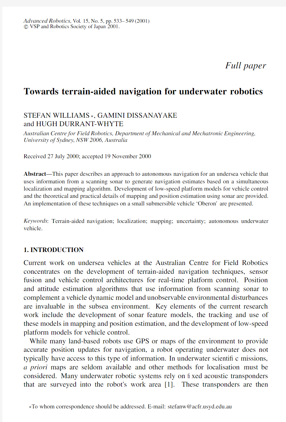
The experimental platform used for the work reported in this paper is a mid-size submersible robotic vehicle called Oberon designed and built at the Australian Cen-tre for Field Robotics(see Fig.1).The vehicle is equipped with two scanning low-frequency terrain-aiding sonars and a color CCD camera,together with bathy-ometric depth sensors,a ber optic gyroscope and a magneto-inductive compass with integrated two-axis tilt sensor[7].This vehicle is intended primarily as a re-search platform upon which to test novel sensing strategies and control methods. Autonomous navigation using the information provided by the vehicle’s on-board sensors represents one of the ultimate goals of the project[8].
Towards terrain-aided navigation535
Figure1.Oberon at sea.
3.FEATURE-BASED POSITION ESTIMATION
This section presents a feature based localisation and mapping technique used for generating vehicle position estimates.By tracking the relative position between the
vehicle and identi able features in the environment,both the position of the vehicle and the position of the features can be estimated simultaneously.The correlation information between the estimates of the vehicle and feature locations is maintained to ensure that consistent estimates of these states are generated.
3.1.The estimation process
The localization and map building process consists of a recursive,three-stage procedure comprising prediction,observation and update steps using an extended Kalman lter(EKF)[3].The Kalman lter is a recursive,least-squares estimator and produces at time k a minimum mean-squared error estimate O x.k j k/of the state x.k/given a series of observations,Z k D[z.1/:::z.k/]:
O x.k j k/D E£x j Z k¤:(1) The lter fuses a predicted state estimate O x.k j k?1/with an observation z.k/of
the state x.k/to produce the updated estimate O x.k j k/.For the SLAM algorithm the EKF is used to estimate the pose of the vehicle x v.k/along with the positions of the N observed features x i.k/;i D1:::N.In the current implementation,the vehicle pose is made up of the two-dimensional position.x v;y v/and orientation ?v of the vehicle.An estimate of vehicle ground speed,V v,slip angle,°v,and the gyro rate bias,P?bias,is also generated by the algorithm.The‘slip angle’°v is the angle between the vehicle axis and the direction of the velocity vector.Although the thrusters that drive the vehicle are oriented in the direction of the vehicle axis,
the slip angle is often non-zero due to disturbances caused by the deployed tether and currents.A schematic diagram of the vehicle model is shown in Fig.2.
3.1.1.Prediction.The prediction stage uses a model of the motion of the vehicle to predict the vehicle position,O x v.k j k?1/,at instant k given the information
536S.Williams et al.
Figure 2.The vehicle model currently employed with the submersible vehicle.The positioning lter estimates the vehicle position,.X v ;Y v /,orientation,?v ,velocity,V v and slip angle °v .The frame of reference used is based on the north-east-down alignment commonly used in aeronauticalengineering applications.The x-axis is aligned with the compass generated north reading.
available to instant k ?1.A constant acceleration model,shown in (2),is used for this purpose:
P x v
D V v cos .?v C °v /C v x ;P y v
D V v sin .?v C °v /C v y ;(2)P ?
v D P ?gyro ?P ?bias C v ?;P V
v D v V ;P °v D v °;
P ?
bias D v bias ;where v x ,v y ,v ?,v V ,v °and v bias are assumed to be zero-mean,temporally uncorrelated gaussian process noise errors with variance ?2x ,?2y ,?2?,?2V ,?2°and ?2bias respectively.The standard deviations for these noise parameters are shown in Table 1.The rate of change of vehicle ground speed,P V v ,and slip angle,P °v ,are assumed to be driven by white noise.The ber-optic gyroscope measures the vehicle yaw rate and is used as a control input to drive the orientation estimate.Given the small submerged inertia,relatively slow motion and large drag-coef cients induced by the open frame structure of the vehicle and the deployed tether,the model described by (2)is able to capture the motion of the vehicle.
In order to implement the lter,the discrete form of the vehicle model is used to predict the vehicle state O x v .k j k ?1/given the previous estimate O x v .k ?1j k ?1/.The discrete,non-linear vehicle prediction equation,F v ,is shown in (4):
O x v .k j k ?1/D F v .O x v .k ?1j k ?1/;u.k//;(3)
Towards terrain-aided navigation537 Table1.
SLAM lter parameters
Sampling period1T0:1s
Vehicle x process noise SD?x0:025m
Vehicle y process noise SD?y0:025m
Vehicle heading process noise SD??0:6o
Vehicle velocity SD?v0.01m/s
Vehicle slip angle SD?°1:4o
Gyro bias SD?bias0:3o/s
Gyro measurement SD?gyro0:6o/s
Compass SD?compass2:9o
Range measurement SD?R0:1m
Bearing measurement SD?B1:4o
Sonar range20m
Sonar resolution0:1m
where F v is de ned by:
O x v D O x v C1T O V v cos.O?v C O°v/;
O y v D O y v C1T O V v sin.O?v C O°v/;(4)
O?v D O?v C1T.P?gyro?P?bias/;
O V v D O V v;
O°v D O°v;
O P?bias D O P?bias;
with the discrete timestamps.k j k?1/and.k?1j k?1/omitted for conciseness. The features that are tracked in the map are assumed to be stationary over time.This is not a necessary condition given the formulation of the SLAM algorithm using an EKF.However,tracking moving features in the environment is not considered feasible at this time given the available sensors nor is it likely to aid in navigation since accurate models of bodies moving underwater are not likely to be available.This assumption yields a simple feature map prediction equation,F m:
O x i.k j k?1/D O x i.k?1j k?1/:(5) The covariance matrix of the vehicle and feature states,O P.k j k?1/,is predicted us-ing the non-linear state prediction equation.The predicted covariance is computed using the gradient of the state propagation equation linearized about the current vehicle state estimate,r F v,and about the control input model,r F u,the process noise model,Q,and the control noise model,U.The lter parameters used in this application are shown in Table1.
O P.k j k?1/D r F v O P.k?1j k?1/r F T v C r F u U.k j k?1/r F T u C Q.k j k?1/;(6)
538S.Williams et al.
with
U.k j k?1/D diag £
?2gyro
¤
;(7)
and
Q.k j k?1/D diag £
?2x?2y?2??2V?2°?2bias
¤
:(8)
3.1.2.Observation.There are two types of observations involved in the map building process as implemented on the vehicle.The rst is the observation of the orientation from the output of the magneto-inductive compass.The lter generates an estimate of the current yaw of the vehicle by fusing the predicted yaw estimate with the compass output.A shaping state that estimates the yaw rate bias of the gyroscope is also generated.The yaw measurements are incorporated into the SLAM lter using the yaw observation estimate,O z?.k j k?1/,as shown in(9):
O z?.k j k?1/D O x?.k j k?1/:(9) The compass observations are assumed to be corrupted by zero-mean,temporally uncorrelated white noise with variance?compass.
z compass.k/D?.k/C w compass:(10) There is always a danger that a compass will be affected by ferrous objects in the environment and transient magnetic elds induced by large currents,such as those generated by the vehicle’s thrusters.While this may the case,in practice the compass does not seem to be affected to a large degree by the vehicle’s thrusters. In addition,the unit is equipped with a magnetic eld strength alarm.When the strength of the magnetic eld increases,the alarm is signaled,indicating that the current observation may be in doubt.
Terrain feature observations are made using an imaging sonar that scans the horizontal plane around the vehicle.Point features are extracted from the sonar scans and are matched against existing features in the map.The feature matching algorithm will be described in more detail in Section4.The observation consists of a relative distance and orientation from the vehicle to the feature.The terrain feature observations are assumed to be corrupted by zero-mean,temporally uncorrelated white noise with variance?R and?B respectively.The predicted observation, O z i.k j k?1/,when observing landmark‘i’located at O x i can be computed using the non-linear observation model H i.O x v.k j k?1/;O x i.k j k?1//:
O z i.k j k?1/D H i.O x v.k j k?1/;O x i.k j k?1//;(11) where H i is de ned by:
O z i R D p.O x v?O x i/2C.O y v?O y i/2;
Towards terrain-aided navigation539
O z iμD arctan
.O y v?O y i/
.O x v?O x i/
′
?O?v;
with the discrete timestamps.k j k?1/once again omitted for conciseness.
For both types of observation,the difference between the actual observation,z.k/, and the predicted observation,O z.k j k?1/,is termed the innovationo.k j k?1/:
o.k j k?1/D z.k/?O z.k j k?1/:(12)
The innovation covariance,S.k j k?1/,is computed using the current state covari-ance estimate,O P.k j k?1/,the gradient of the observation model,r H.k j k?1/,and the covariance of the observation model R.k j k?1/:
S.k j k?1/D r H.k j k?1/O P.k j k?1/r H.k j k?1/T C R.k j k?1/;(13)
with:
R?.k j k?1/D diag £
?2compass
¤
;(14)
and:
R i.k j k?1/D diag £
?2R?2B
¤
:(15)
3.1.3.Update.The state estimate can now be updated using the optimal gain matrix W.k/.This gain matrix provides a weighted sum of the prediction and observation,and is computed using the innovation covariance,S.k j k?1/,and the predicted state covariance,O P.k j k?1/.This is used to compute the state update O x.k j k/as well as the updated state covariance O P.k j k/:
O x.k j k/D O x.k j k?1/C W.k j k?1/o.k j k?1/;(16) O P.k j k/D O P.k j k?1/?W.k j k?1/S.k j k?1/W.k j k?1/T;(17) where:
W.k j k?1/D O P.k j k?1/r H.k j k?1/S?1.k j k?1/:(18)
4.FEATURE EXTRACTION FOR LOCALIZATION
The development of autonomous map-based navigation relies on the ability of the system to extract appropriate and reliable features with which to build maps.Point features are identi ed from the sonar scans returned by the imaging sonar and are used to build up a map of the environment.
The extraction of point features from the sonar data is essentially a three-stage process.The range to the principal return must rst be identi ed in individual pings. This represents the range to the object that has produced the return.The principal returns must then be grouped into clusters.Small,distinct clusters can be identi ed as point features,and the range and bearing to the target estimated.Finally,the range and bearing information must be matched against existing features in the map.This
540S.Williams et al.
Figure3.An image captured from the submersible of one of the sonar targets deployed at the eld test site.
section provides more details of the feature identi cation algorithms used to provide observations for the lter.
4.1.Sonar targets
Sonar targets are currently introduced into the environment in which the vehicle will operate(see Fig.3)in order to obtain identi able and stable features.A prominent portion of the reef wall or a rocky outcropping might also be classi ed as a point feature.If the naturally occurring point features are stable they will also be incorporated into the map.Development of techniques to extract terrain aiding information from more complex natural features,such as coral reefs and the natural variations on the sea oor,is an area of active research.The ability to use natural features will allow the submersible to be deployed in a larger range of environments without the need to introduce arti cial beacons.
The sonar targets produce strong sonar returns that can be charaterized as point features for the purposes of mapping(see Fig.5a).The lighter sections in the scan indicate stronger intensity returns.In this scan,two sonar targets are clearly visible and can easily be characterized as point features.(The features extracted by the algorithm are shown in Fig.5b.)More details of the feature extraction algorithms are presented in the following subsections.
4.2.Principal returns
The data returned by the SeaKing imaging sonar consists of the complete time history of each sonar ping in a discrete set of bins scaled over the desired range. The rst task in extracting reliable features is to identify the principal return from the ping data.The principal return is considered to be the start of the maximum energy component of the signal above a certain noise threshold.Figure4shows a single ping taken from a scan in the eld.This return is a re ection from one of the sonar targets and the principal return is clearly visible.The return exhibits very
Towards terrain-aided navigation541
Figure4.(a)A single SeaKing ping showing the raw ping,the moving average and the computed principal return.This ping is a re ection from one of the sonar targets and shows very good signal to noise ratio.The dashed line marks the principal return.(b)A single SeaKing ping re ected from the reef surrounding the vehicle showing the raw ping and the moving average.The terrain returns are distinguishable from the target returns by the fact that the high energy returns are spread over a much wider section of the ping.The large amplitude return at low range in this ping results from the interface between the oil- lled sonar transducer housing and the surrounding sea https://www.360docs.net/doc/3b4527937.html,rge amplitude returns are ignored if they are below2.0m from the vehicle.
good signal to noise ratio making the extraction of the principal returns relatively straightforward.
At present the vehicle relies on the sonar targets as its primary source of navigation information.It is therefore paramount for the vehicle to reliably identify returns originating from the sonar targets.Examination of the returns generated by the targets shows that they typically have a large magnitude return concentrated over a very short section of the ping.This differs from returns from other objects in the environment such as rocks and the reef walls that tend tend have high energy returns spread over a much wider section of the ping as seen in Fig.4b.
4.3.Identi cation of point features
Following the extraction of the principal return from individual pings,these returns are then processed to nd regions of constant depth within the scan that can be classi ed as point features.Sections of the scan are examined to nd consecutive pings from which consistent principal return ranges are located.The principal returns are classi ed as a point feature if the width of the cluster is small enough to be characterised as a point feature and the region is spatially distinct with respect to other returns in the scan[9].The bearing to the feature is computed using the center
542S.Williams et al.
Figure5.(a)A scan in the eld showing sonar targets.(b)The principal returns(+)and the extracted point features(e)from the scan in(a).
of the distribution of principal returns.The range is taken to be the median range of the selected principal returns.
A scan taken in the eld is shown in Fig.5a.Two targets are clearly visible in the scan along with a section of the reef wall.Figure5b shows the principal returns selected from the scan along with the point features extracted by the algorithm.Both targets are correctly classi ed as point features while the returns originating from the reef are ignored.Future work concentrates on using the information available from the unstructured natural terrain to aid in navigation.
4.4.Feature matching
Once a point feature has been extracted from a scan,it must be matched against known targets in the environment.A two-step matching algorithm is used in order to reduce the number of targets that are added to the map(see Fig.6).
When a new range and bearing observation is received from the feature extraction process,the estimated position of the feature is computed using the current estimate of vehicle position.This position is then compared with the estimated positions of the features in the map using the Mahanabolis distance[3].If the observation can be associated to a single feature the EKF is used to generate a new state estimate. An observation that can be associated with multiple targets is rejected since false observations can destroy the integrity of the estimation process.
If the observation does not match to any targets in the current map,it is compared against a list of tentative targets.Each tentative target maintains a counter indicating the number of associations that have been made with the feature as well as the last observed position of the feature.If a match is made,the counter is incremented and the observed position is updated.When the counter passes a threshold value, the feature is considered to be suf ciently stable and is added to the map.If the
Towards terrain-aided navigation543
Figure6.The feature-matching algorithm.
potential feature cannot be associated with any of the tentative features,a new tentative feature is added to the list.Tentative features that are not reobserved are removed from the list after a xed time interval has elapsed.
5.EXPERIMENTAL RESULTS
The SLAM algorithms have been tested during deployment in a natural environment off the coast of Sydney,Australia.The submersible was deployed in a natural inlet with the sonar targets positioned in a straight line at intervals of10m.The vehicle controls were set to maintain a constant heading and altitude during the run.Once the vehicle had reached the end of its tether(approximately50m)it was turned around and returned along the line of targets.The slope of the inlet in which the vehicle was deployed meant that the depth of the vehicle varied between approximately1and5m over the course of the run.
The plot of the nal map obtained by the SLAM algorithm(shown in Fig.7) clearly shows the position of the sonar feature targets along with a number of tentative targets that are still not con rmed as suf ciently reliable.Some of the tentative targets are from the reef wall,while others come from returns off of the tether.These returns are typically not very stable and therefore do not get incorporated into the SLAM map.The absolute location of all the potential point targets identi ed based on the sonar principal returns are also shown in this map. These locations were computed using the estimated vehicle location at the instant of the corresponding sonar return.The returns seen near the top and bottom of the
544S.Williams et al.
Figure7.Path of robot shown against nal map of the environment.The vehicle position estimates are spaced evenly in time over the run.It is evident that the vehicle speed changes during the run as a function of the tether deployment.The estimated position of the features are shown as circles with the covariance ellipses showing their95%con dence bounds.Tentative targets that have not yet been added to the map are shown as‘+’.The series of tentative targets towards the top of the image occur from the reef wall.These natural point features tend not to be very stable,though,and are thus not incorporated into the map.
map are from the reef walls.As can be seen,large clusters of returns have been successfully identi ed as targets.
Since there is currently no absolute position sensor on the vehicle,the perfor-mance of the positioning lter cannot be measured against ground truth at this time. In previous work,it was shown that the estimator yields consistent results in the controlled environment of the swimming pool at the University of Sydney[10]. To verify the performance of the lter,the innovation sequence can be monitored to check the consistency of the estimates.Figure8shows that the innovation se-quences are within the covariance bounds computed by the algorithm.
The state estimates can also be monitored to ensure they are yielding sensible estimates.The vehicle is attached to an on-shore command station via a tether.This tether is deployed during the mission and a number of oating buoys keep it from dragging on the ground.The tether catenary creates a force directed back along its length.The effects of this force are evident in the slip angle experienced by the vehicle.When the vehicle executes a large turn,the slip angle tends to change direction.Figure9shows the slip angle estimates throughout the run.Shortly after the sharp turn at360s,the mean slip angle estimate changes sign—re ecting the fact that the tether has changed its position relative to the vehicle.
In addition to the identi ed target returns,strong energy returns from the reef walls and the sea oor can also be extracted from the sonar pings.In Fig.10these
Towards terrain-aided navigation545
Figure8.The range and bearing innovation sequences plotted against their95%con dence bounds. The innovation is plotted as a solid line while the con dence bounds are the dash-dot lines.
Figure9.(a)The vehicle orientation and(b)slip angle computed by the algorithm.The vehicle executes a180±turn at approximately the360s.The mean slip estimate changes from a positive to negative value at this time re ecting the change in the force induced by the tether catenary.
strong returns have been plotted.The return points are color coded to re ect the depth at which the observation was taken.The shape of the inlet can be clearly seen and it is evident that the vehicle is observing the sea oor behind itself as it moves deeper along the inlet.Figure11shows a close up view of the same scene showing the vehicle position estimates more clearly.
546S.Williams et al.
Figure10.Path of robot shown against nal map of the environment.The estimated position of the features are shown as a vertical column of circles.The strong sonar returns are color coded with the depth at which they were observed with a darker point indicating a deeper depth.The shape of the inlet is clearly visible from this plot.The estimated vehicle positions are shown spaced evenly in time.
6.SUMMARY AND CONCLUSIONS
In this paper,it has been shown that SLAM is practically feasible using arti cial targets introduced into a natural terrain environment on Sydney’s shore-line.By using terrain information as a navigational aid,the vehicle is able to detect unmodeled disturbances in its motion induced by the tether drag and the effect of currents.
The focus of future work is on representing natural terrain in a form suitable for incorporation into SLAM.This will enable the vehicle to be deployed in a broader range of environments without the need to introduce arti cial beacons.Another outstanding issue is that of map management.As the number of calculations required to maintain the state covariance estimates increases with the square of the number of beacons in the map,criteria for eliminating features from the map as well as for partitioning the map into submaps becomes important.This is especially true for longer missions in which the number of available landmarks is potentially quite large.Finally,integration of the localisation and map building with mission planning is under consideration.This will allow decisions concerning sensing strategies to be made in light of the desired mission objectives.
Towards terrain-aided navigation547
Figure11.A close-up view of the path of robot shown against nal map of the environment.The estimated position of the features are shown as a vertical column of circles.The estimated vehicle positions are shown spaced evenly in time.
REFERENCES
1.L.Whitcomb,D.Yoerger,H.Singh and J.Howland,Advances in underwater robot vehicles for
deep ocean exploration:navigation,control and survey operations,in:Proc.9th Int.Symp.on Robotics Research,Snowbird,UT,pp.346–353(1999).
2.J.A.Castellanos,J.M.M.Montiel,J.Neira and J.D.Tardos,Sensor in uence in the performance
of simultaneous mobile robot localization and map building,in:Proc.6th Int.Symp.on Experimental Robotics,Sydney,pp.203–212(1999).
3.M.W.M.G.Dissanayake,P.Newman,H.F.Durrant-Whyte,S.Clark and M.Csorba,An
experimental and theoretical investigation into simultaneous localisation and map building,in: Proc.6th Int.Symp.on Experimental Robotics,Sydney,pp.171–180(1999).
4.H.J.S.Feder,J.J.Leonard and C.M.Smith,Adaptive sensing for terrain aided navigation,in:
Proc.IEEE Oceanic Engineering Society:OCEANS’98,New York,V ol.1,pp.336–341(1998).
5.J.J.Leonard and H.F.Durrant-Whyte,Simultaneous map building and localisation for an
autonomous mobile robot,in:Proc.IEEE/RSJ Int.Workshop on Intelligent Robots and Systems, New York,pp.1442–1447(1991).
6.W.D.Rencken,Concurrent localisation and map building for mobile robots using ultrasonic
sensors,in:Proc.IEEE/RSJ Int.Conf.on Intelligent Robots and Systems,New York,V ol.3, pp.2192–2197(1993).
7.S.Williams,P.Newman,S.Majumder,J.Rosenblatt and H.Durrant-Whyte,Autonomous transect
surveying of the Great Barrier Reef,in:Proc.Australian Conf.on Robotics and Automation, Brisbane,pp.16–20(1999).
8.P.Newman and H.F.Durrant-Whyte,Toward terrain-aided navigation of a ssubsea vehicle,in:
Proc.FSR’97Int.Conf.on Field and Service Robotics,Canberra,pp.244–248(1997).
9.P.Newman,On the structure and solution of the simultaneous localisation and map building
problem,PhD Thesis,University of Sydney(1999).
548S.Williams et al.
10.S.Williams,P.Newman,D.Dissanayake and H.Durrant-Whyte,Autonomous underwater
simultaneous localisation and mapping,in:Proc.IEEE Int.Conf.on Robotics and Automation, San Francisco,CA,V ol.2,pp.1793–1798(2000).
11.R.Bauer and W.D.Rencken,Sonar feature based exploration,in:Proc.1995IEEE/RSJ Int.
Conf.on Intelligent Robots and Systems,Los Alamitos,CA,V ol.1,pp.148–153(1995).
12.R.A.Brooks,A robust,layered control system for a mobile robot,IEEE J.Robotics Automat.2
(1),14–23(1986).
13.J.J.Leonard,R.N.Carpenter and H.J.S.Feder,Stochastic mapping using forward look sonar,
in:Proc.FSR’99Int.Conf.on Field and Service Robotics,Pittsburg,PA,pp.69–74(1999). 14.P.Maybeck,Stochastic Models Estimation and Control,V ol.1.Academic Press,New York
(1982).
15.S.Scheding,G.Dissanayake,E.Nebot and H.Durrant-Whyte,Slip modelling and aided inertial
navigation of an LHD,in:Proc.IEEE Int.Conf.on Robotics and Automation,Albuquerque,NM, pp.1904–1909(1997).
16.L.Whitcomb,D.Yoerger,H.Singh and Mindell,Towards precision robotic maneuvering,
survey,and manipulation in unstructured undersea environments,in:Robotics Research:Proc.
8th Int.Symp.,pp.346–353.Springer-V erlag,London(1998).
ABOUT THE AUTHORS
Stefan B.Williams received the BASc degree(1st class honours)in Systems
Design Engineering from the University of Waterloo in Waterloo,ON,Canada
in1997.He is currently completing the requirements for a PhD in Mechatronic
Engineering(Field Robotics)at the Australian Centre for Field Robotics in
the Department of Mechanical and Mechatronic Engineering at the University
of Sydney,Australia.His research work focuses on robotics and arti cial
intelligence,and concentrates on the development of terrain-aided navigation
techniques,sensor fusion and vehicle control architectures for real-time platform control.He has been involved in numerous projects including an autonomous underwater vehicle, an autonomous boat,the design of a modular walking robot and the study of force-feedback haptic systems.
Gamini Dissanayake graduated in Mechanical/Production Engineering from the
University of Peradeniya,Sri Lanka.He received his MSc in Machine Tool
Technology and PhD in Mechanical Engineering(Robotics)from the University
of Birmingham,England in1981and1985,respectively.He was a lecturer at
the University of Peradeniya and the National University of Singapore before
joining the University of Sydney,Australia,where he is currently a Senior
Lecturer attached to the Australian Centre for Field Robotics.His current research
interests are in the areas of localization and map building for mobile robots,
navigation systems,dynamics and control of mechanical systems,cargo handling,
optimization,and path planning.
Hugh Durrant-Whyte received the BSc(Eng)degree(1st class honours)in
Mechanicaland Nuclear Engineering from the University of London,UK,in1983,
and the MSE and PhD degrees,both in Systems Engineering,from the University
of Pennsylvania,USA,in1985and1986,respectively.From1987to1995,he was
a Senior Lecturer in Engineering Science,University of Oxford,UK and a Fellow
of Oriel College Oxford.Since July1995he has been Professor of Mechatronic
Engineering at the Department of Mechanical and Mechatronic Engineering,the
University of Sydney,Australia,where he leads the Australian Centre for Field
Towards terrain-aided navigation549 Robotics,a Commonwealth Key Centre of Teaching and Research.His research work focuses on automation in cargo handling,surface and underground mining,defence,unmanned ight vehicles, and autonomous sub-sea vehicles.
水下机器人地形辅助导航(英文)
Advanced Robotics,Vol.15,No.5,pp.533–549(2001) óVSP and Robotics Society of Japan2001. Full paper Towards terrain-aided navigation for underwater robotics STEFAN WILLIAMS¤,GAMINI DISSANA YAKE and HUGH DURRANT-WHYTE Australian Centre for Field Robotics,Department of Mechanical and Mechatronic Engineering, University of Sydney,NSW2006,Australia Received27July2000;accepted19November2000 Abstract—This paper describes an approach to autonomous navigation for an undersea vehicle that uses information from a scanning sonar to generate navigation estimates based on a simultaneous localization and mapping algorithm.Development of low-speed platform models for vehicle control and the theoretical and practical details of mapping and position estimation using sonar are provided. An implementation of these techniques on a small submersible vehicle‘Oberon’are presented. Keywords:Terrain-aided navigation;localization;mapping;uncertainty;autonomous underwater vehicle. 1.INTRODUCTION Current work on undersea vehicles at the Australian Centre for Field Robotics concentrates on the development of terrain-aided navigation techniques,sensor fusion and vehicle control architectures for real-time platform control.Position and attitude estimation algorithms that use information from scanning sonar to complement a vehicle dynamic model and unobservable environmental disturbances are invaluable in the subsea environment.Key elements of the current research work include the development of sonar feature models,the tracking and use of these models in mapping and position estimation,and the development of low-speed platform models for vehicle control. While many land-based robots use GPS or maps of the environment to provide accurate position updates for navigation,a robot operating underwater does not typically have access to this type of information.In underwater scienti c missions, a priori maps are seldom available and other methods for localisation must be considered.Many underwater robotic systems rely on xed acoustic transponders that are surveyed into the robot’s work area[1].These transponders are then ¤To whom correspondence should be addressed.E-mail:stefanw@https://www.360docs.net/doc/3b4527937.html,.au
水库水下地形测量中GPS结合测深仪应用
水库水下地形测量中GPS结合测深仪应用 摘要:随着GPS技术的不断发展,RTK技术的出现和计算机技术的飞速发展,平面定位技术实现了高精度、自动化、数字化和实时化。随着探测技术的数字化和 自动化,为水下地形测量数字化、自动化和水利测量提供了基础,为测绘提供了 先进的手段。文章介绍GPS结合测深仪在水下地形测量中的实际应用、测深设备 的基本工作原理,以及在测量过程中会遇到的问题及处理方法。 关键词:水下地形测量;GPS;测深仪 0引言 水下地形测量在许多工程建设项目上有着重要的作用,它可以为桥梁、码头、水库、港口等工程建设项目提供必要的基础数据,是现代水利工程中的一项重要 工程技术。由于传统水下测量模式存在着诸多弊端,譬如测量难度大、数据不精确、不能反映真实水下地形等问题。现代的“GPS+数据处理软件+测深仪”的测量 模式逐步取代传统的测量模式。 1控制测量 水下地形测量应与地面上的国家控制点或高级控制点构成统一整体,只在需 求的情况下单独建立水下地形测量的高程和平面控制。 2水下地形测量 2.1数字测深仪的工作原理 数字测深仪是利用声波的传导特性,实现水下地形测量的仪器。数字测深仪 的原理是通过振荡器发出超声波后遇到障碍物,再通过接收器接收反射回的声波,通过时间差t,求出距离D=Ct/2,C为超声波波速。 2.2水下地形测量系统组成 水下地形测量利用GPSRTK和数字测深仪、计算机联合使用作业。作业人员 应在测量前将测区的范围图导入计算机,按规范要求在测量前设计好测线,测量 时应按照测线进行测量活动。利用RTK的定位定向功能指导船只航行。利用计算 机的测深软件实时观测船只的航向、航速、船只的平面坐标、水深及RTK的解状态。声波在水中传播速度受到水温、水深、水的盐度等因素的影响,因此要进行 相关参数的修改,同时可以利用声抛仪辅助修改相关参数,用以获得准确的测深 数据。 2.3水下地形测量工作原理 用测深仪专用连接杆连接测深仪与RTK,再将连接好的连接杆安装在船只上,将测深仪没入水下,连接杆要始终保持垂直于水面,并保持连接杆与船只的相对 位置不变,RTK可以实时的获得平面坐标与高程坐标,由RTK所获得的高程减去RTK距水面的高度。同时船只有一定程度的摇晃及水流的波动,因此,此时所获 得的水面高程仅为参考值。所以要求我们在工作时选择较大型的船只,同时注意 保持航速,航速不宜过快,保证数据的准确性。 2.4水下地形测量具体过程 实际工作中三人即可完成操作,由一人驾驶船只,船只要按既定航线行驶, 同时保持船只行驶速度,速度不宜快。一人利用电脑操作GPS接收机和测深仪, 实时观测数据及解状态,另一人利用声抛仪每隔一段距离测量一次声速,用以进 行声速改正,如发现问题,及时处理。 2.5设备的安装 所选用的船只尽量选择大而稳的。测深仪的换能器要尽量远离船只的发动机、
机载增强的全球定位系统(GPS)机载辅助导航传感器
编号:CTSO-C196b 日期: 局长授权 批准: 中国民用航空技术标准规定 本技术标准规定根据中国民用航空规章《民用航空材料、零部件和机载设备技术标准规定》(CCAR37)颁发。中国民用航空技术标准规定是对用于民用航空器上的某些航空材料、零部件和机载设备接受适航审查时,必须遵守的准则。 机载增强的全球定位系统(GPS)机载辅助导航传感器 1. 目的 本技术标准规定(CTSO)适用于为机载增强的全球定位系统(GPS)机载辅助导航传感器申请技术标准规定项目批准书(CTSOA)的制造人。本CTSO规定了机载增强的全球定位系统(GPS)机载辅助导航传感器为获得批准和使用适用的CTSO标记进行标识所必须满足的最低性能标准。CTSO-C196b包含了CTSO-C145d中的许多技术性能改进,但不包括星基增强系统(SBAS)技术要求以及SBAS 星基增强的运行特点。 注:本次修订允许申请人使用CTSO-C206 GPS电路板组件(CCA)功能传感器作为CTSO申请的重要组成部分。 2. 适用范围 本CTSO适用于自其生效之日起提交的申请。按本CTSO批准的设备,其设计大改应按CCAR-21-R4第21.353条要求重新申请CTSOA。
3. 要求 在本CTSO生效之日或生效之后制造并欲使用本CTSO标记进行标识的机载增强的全球定位系统(GPS)机载辅助导航传感器应满足RTCA/DO-316《全球定位系统/机载增强系统机载设备最低运行性能标准》第2.1节(2009.4.14发布)。 CTSO-C196b申请人可以选择使用CTSO-C206 GPS CCA功能传感器。选择使用CTSO-C206 GPS功能传感器的申请人可凭借CTSO-C206 的CTSOA而获得如下的审定符合性的置信度: ●满足最低性能标准(MPS)第2.1节规定的要求; ●硬件/软件鉴定; ●失效状态类别; ●MPS第2.3节的性能试验(功能鉴定),本CTSO附录1中规定的除外。 使用CTSO-C206 GPS CCA功能传感器的CTSO-C196b申请人应开展附录1中所述的试验,并满足本CTSO其它章节中上述所列几点未涵盖的关于获得CTSO-C196b CTSOA的要求。使用CTSO-C206 GPS CCA功能传感器作为其CTSO-C196b申请一部分的终端制造人,依照CCAR21部,对其获取的CTSO-C196b CTSOA中规定的设计和功能负全部责任。 a.功能 (1) 本CTSO的标准适用于接收信号,并为可结合预期飞行航道输出偏航指令的导航管理单元应用提供位置信息的设备,或者为如
地磁导航技术综述及其与卫星导航等的关系
地磁导航技术综述及其与卫星导航等的关系 (2011-03-01 14:00:45) 转载▼ 标签: 卫星导航 gps 地磁 地磁导航 it 1、什么是地磁场? 地磁场是地球的固有资源,为航空、航天、航海提供了天然的坐标系。自从1989年美国Cornell 大学的Psiaki等人率先提出利用地磁场确定卫星轨道的概念以来,这一方向成为国际导航领域的一大研究热点。地磁导航具有无源、无辐射、全天时、全天候、全地域、能耗低的优良特征,其原理是通过地磁传感器测得的实时地磁数据与存储在计算机中的地磁基准图进行匹配来定位。由于地磁场为矢量场,在地球近地空间内任意一点的地磁矢量都不同于其他地点的矢量,且与该地点的经纬度存在一一对应的关系。因此,理论上只要确定该点的地磁场矢量即可实现全球定位。 于地球内部的磁场称为内源场,约占地球总磁场的95%。内源场主要来自地球的液态外核。外核是熔融的金属铁和镍,它们是电流的良导体,当地球旋转时,产生强大的电流,这些电流产生了地球磁场。地磁场总体像个沿地球旋转轴放置在地心的磁铁棒产生的磁场,它内源场的主要部分,也是地磁场的主要特征,占到总地磁场的80%~85%,称为偶极子场。内源场还有五个大尺度的非偶极子场,称为磁异常,分别为南大西洋磁异常,欧亚大陆磁异常,北非磁异常,大洋洲磁异常和北美磁异常,主要来源于地壳岩石产生的磁场。起源于地球外的磁场称为外源场,主要由太阳产生,它占了地球磁场的5%。 地磁场是个随时间变化的场,内源场引起的变化称为长期变化,有磁场倒转和地磁场向西飘移。地磁场每5000~50000年倒转一次,把与现在磁场方向相同的磁场称为正常磁场(磁场从南极附近出来,回到北极),把与现在磁场方向相反的称为倒转磁场,地质时期上出现了四个较大的倒转期,现在为布容正向期,往前有松山反向期,高斯正向期和吉尔伯特反向期。固体地球外部的各种电流体系引起的地磁场变化快,时间短,称为短期变化。短期变化又分为平静变化和扰动变化,其中平静变化包括太阳静日变化和太阴日变化,扰动变化包括磁暴、亚暴、钩扰、湾扰和地磁脉动。磁暴、钩扰、湾扰的发生与太阳活动有关,太阳活动高年,这些短期变化频繁发生,而且强度很大,变化剧烈。亚暴与极光有关。 地磁场能够反射粒子流,它把我们的地球包围起来,使我们免受高速太阳风的辐射和伤害,为我们提供了一个无形的屏障。 2、什么是地磁导航? 人们利用地磁场导航已经有四百年的历史了,现在发现鸽子,海滩,蝙蝠和乌龟等大量动物都用地球磁场来导航。
面向地形辅助导航的地形信息分析
面向地形辅助导航的地形信息分析 刘鹰1,张继贤o,柳健1 (1华中理工大学电信系图像教研室,武汉430074) (o中国测绘科学研究院 100039) 摘要:对地形D EM(数字高程模型)数据中所含信息的多少及信息的可利用程度进行了分析,地形信息的分析结果可作为地形辅助导航和飞行路线选择的参考依据。 关键词:惯性导航系统;地形轮廓线匹配;地形高程模型 中图分类号:P20 文章标识码:A 文章编号:1000-3177(2000)58-0021-03 1 引 言 在飞行过程中,一般需要利用地形辅助导航系统来纠正INS(惯性导航系统)所积累的导航定位误差,TERCOM(地形轮廓线匹配)是其中一种比较典型的辅助导航系统。它的工作原理说明,飞行器位置的确定是利用实测的地形高程剖面与根据INS位置信息和地形高程数据库计算所得的地形高程剖面,按一定的算法作相关分析,所得的相关极值点对应的位置就是飞行器的当前位置。然而,由匹配计算理论及飞行实验我们知道,整块平坦地区的误匹配概率要比有一定起伏地区的误匹配概率高。因此在航迹规划时,我们要让航迹尽量避开那些连续的平坦区域,而选择具有一定起伏的区域,在这里,我们称前者的信息量少,而后者则相反。但是,在进行地形的匹配搜索运算时,考虑到不同地形块之间的相似性,因此尽管有些地形的信息量较大,但由于相关性太大而导致可利用的程度不高,所以要对地形进行相关程度的分析。用以上分析的结果来指导航迹的选择,进行飞行任务的合理规划。 2 地形信息的分析 2.1 地形特征参数的选择 地形信息的分析作为地形分析的一部分,是通过研究与地形辅助导航密切相关的地形特征因素及各因素的贡献,从而为地形信息分析提供实验和理论依据。理论上来说,一旦地形的高程值给定之后,有关地形的信息就已经完全得到了。因此,根据回归分析法研究常用特征参数之间的关系,我们选取以下7项特征参数作为地形分析的主要度量指标: 1分形维数; o地形标准差; ?X,Y方向相关长度; ?X,Y方向块相似度; ?粗糙度; ?斜率均方差; ?频域收敛度。 这7个特征参数基本上可以反映出地形的主要情况。因此,我们就可以根据这几个参数来衡量地形的信息量大小。 2.2 地形的类型初判 在对某块地形作直观描述时,我们常用到“平原、丘陵、高山”等字眼,这些词粗略地反映了地形的概貌。用数学方法和语言来描述,就是反映地形数据的平均高程值大小和标准差的大小。例如,我们平时称为“平原”的地区,其对应的高程值和标准差值都比较小。为了对地形的类型作进一步较精确的分类,我们在此还引入了地形的另一特征参数地形的自相似系数H。 H和地形分形维数D之间的关系是: D=3-H(1)由分形理论分析可知,H参数反映了地形微起伏的复杂程度或表面的破碎程度,是对地形复杂情况的一种抽象和概括,也直接影响地形的匹配概率和匹配精度。H值越大,则地形表面越简单,信息量较小;H值越小,则地形的表面越复杂,信息量相对来说较大。根据经验值取分形门限H为: 0.7~1.0:信息贫乏区 0.3~0.7:可匹配区 0.0~0.3:地形危险区 作者简介:刘鹰,男,(1975~)华中理工大学电信系信息与信号处理专业硕士研究生,主要研究方向为图像处理,模式识别和信号处理。 21
【CN209485376U】共享单车安全导航辅助装置【专利】
(19)中华人民共和国国家知识产权局 (12)实用新型专利 (10)授权公告号 (45)授权公告日 (21)申请号 201920526696.X (22)申请日 2019.04.18 (73)专利权人 吉林大学 地址 130012 吉林省长春市前进大街2699 号 (72)发明人 王楠 张峻伟 吉林杰 张茜 陈秋昀 庞礼健 杜瑞 刘建业 刘涵 (74)专利代理机构 长春吉大专利代理有限责任 公司 22201 代理人 朱世林 张晶 (51)Int.Cl. G01C 21/36(2006.01) G01C 21/26(2006.01) B62J 3/00(2006.01) B62J 6/00(2006.01) (54)实用新型名称共享单车安全导航辅助装置(57)摘要本实用新型属于车辆导航技术领域,涉及一种震动与灯光辅助骑行的导航装置。包括智能把手和智能灯环,智能把手设置于共享单车两侧的把手处,以代替原有把手位置;所述智能灯环设置于共享单车的车头上;智能把手8包括LED灯A、震动马达、主芯片A和锂电池A;主芯片A与LED灯A、震动马达相连接,以发送控制信号;智能灯环由LED灯B、主芯片B、锂电池B、蓝牙模块、显示屏组成;蓝牙模块与主芯片B相连接,以接收第三方App导航软件的导航数据;主芯片B与显示屏和LED灯B相连接,以发送控制信号。有效解决骑行者骑单车时使用手机导航不方便的问题,也不再需要单独设计新的导航系统,节约开发成本,市 场上已有的手机导航APP能够继续被用户使用。权利要求书1页 说明书4页 附图3页CN 209485376 U 2019.10.11 C N 209485376 U
水下辅助导航综述
水下辅助导航综述 文章介绍了水下辅助导航系统的研究现状;分析了目前常用的水下辅助导航算法,尤其对水下地形辅助导航进行了比较深入的分析,它是目前广泛使用的水下导航技术,随着水下机器人的发展,水下地形辅助导航必将越来越收到研究者的关注,文中也分析了未来地形辅助导航的研究热点。 标签:水下导航;地形辅助导航;综述 1 概述 当今空中和陆上的导航系统十分依赖于GPS,它能够提供大范围的精确且连续的位置信息。因此GPS广泛应用于各种移动平台上,包括飞行器、地面车等机器人系统中。尽管如此,但还是在一些特殊的环境,GPS不能使用,必须要考虑其它的导航手段。这类环境包括:水下、太空、地底、室内以及其它GPS接收机受限的环境中(比如:战时受屏蔽区域)。尤其在水中,GPS等电磁传感器无法使用,必须考虑其他的辅助导航定位手段。目前在水下有多种类型的导航定位手段,包括声学,光学,地磁以及地形等方法。 随着海洋资源受到各国的极大关注,海上冲突不断,临海更过纷纷投入水下机器人装备的开发。水下导航是水下机器人的关键组成,由于水下特殊的环境,GPS系统无法使用,因此需要进行水下輔助导航。随着科学技术的发展,各种水下导航技术在不同的应用中发挥了重要的作用,越来越多地收到了人们的关注。目前在GPS受限的情况下,水域机器人的导航定位技术有两类:航迹推算以及辅助导航。 航迹推算主要利用速度加速度传感器来计算机器人的位置,由于测量的误差积分的结果会产生飘移,随着时间的增加误差会增大。典型的推算公式如下: (1) 这里dxn和dqb分别表示机器人的位置和方向的改变量,R(qb)和■(qb)是旋转矩阵,vb、ab和?棕b分别表示速度,加速度以及角速度。n表示惯性导航的第n时刻,b表示机器人本体。在机器人系统中,一般通过融合加速度、陀螺、磁力仪以及速度传感器信息来计算机器人位置。航海常用的导航传感器主要有水压传感器,磁罗盘,陀螺仪,加速度计,IMU (Inertial Measurement Unit),AHRS (Attitude,Heading and Reference System),DVL(Doppler Velocity Log),传感器原理不同,其测量精度相差很大。对于功耗和成本有限的机器人,很多高精度的设备都无法使用,难以达到高精度的导航。 水下的辅助导航主要有声学辅助导航,通常通过声学定位传感器来进行位置计算的,使用的传感器由有长基线或短基线定位传感器。另外,地形辅助导航,视觉辅助导航,地磁辅助导航方式,以及重力辅助导航方式也有诸多研究。
计算机辅助导航技术在骨科手术中的应用
国内讲堂11 继续医学教育 第21卷第12期计算机辅助导航技术在骨科手术中的应用 邱贵兴(中国医学科学院协和医科大学北京协和医院骨科 100710) 作者简介邱贵兴,男,江苏省无锡市人,教授,博士生导师,中华医学会骨科分会主任委员,中华医学会北京分会骨科专业委员会主任委员,中华骨科杂志主编,吴阶平医学基金会理事,中华医学会国际交流与合作工作委员会委员。影像导航技术问世之前,骨科医生在术中,凭借人体的骨骼解剖特点、术前患者的影像学资料(X线片、CT、MRI)和术中的X线透视进行定位。但是,解剖变异或解剖标志的缺乏等往往会导致术中的定位偏差。因此,手术者的实践经验就非常重要。然而,即使是非常有经验的骨科医生,用传统方法进行较精确定位的手术,也有出现偏差的可能性。临床和实验研究已经显示,用传统定位方法行腰椎椎弓根钉植入的失误率为20%~30%。然而,如果 应用影像导航技术,椎弓根钉植入的失误率只有0~4%。近年来,计算机辅助影像导航系统用于术前制定手术计划和术中导航,在手术过程中跟踪手术器械,帮助骨科医生更精确和更安全地进行多种复杂手术。因此,该技术有许多不可替代的优越性,已被越来越广泛地应用于骨科手术中。1 骨科计算机辅助导航技术的简史影像导航,也称为无框架立体定向。1986年Roberts首次报告使用声波数字化仪跟踪手术器械或显微镜的方法,从而开创了无框架立体定向神经外科。随后,Bernett和 Reinhard对超声波系统进行了改进,使导航精度有了一定的提高,但声学环境及温度很容易造成干扰而使导航失败。1991年日本的Wanatabe和美国的Pell相继发明了遥控机械臂定位系统,可以不受瞄准线约束。但因其体积过大,使医生的操作受限。1992年,使用红外线跟踪技术的影像导航系统在美国开始应用于临床。这是世界上首台光学手术导航系统,由于其精度较高,所以成为目前市场上的主流产品。同年,著名的神经外科专家Kevin Foley将光学手术导航系统应用于脊柱外科领域。1995年,Gunkel推出了电磁感应型导航系统,但由于手术室各种金属器械及仪器都会影响电磁场,从而影响其精度,所以未能很好推广。1999年首台完全针对骨科的手术导航系统进入市场。X线透视和红外线跟踪技术、计算机定点手术技术的结合提供了一种新颖的术中影像导航的方法,减少了术中X线透视的缺点。同时,应用术前的CT和MR扫描数据进行骨结构的三维重建,在术前进行手术方案设计,并在术中对正常或病变结构进行精确定位,以协助医生安全、精确地完成手术。2 骨科计算机辅助导航系统的组成及工作原理以X线透视影像导航为例,X线透视法和计算机技术的结合增加了标准透视法的优点,减少了缺点。在“C”型臂透视X线机的图像增强器上安装校准靶,经过一次或多次投照中获得的透视图像和位置校准后,计算机工作站就可以建立起一个透视图 像的模型,将追踪的手术器械与保存的图像叠加在 一起。当手术器械对之前获得的透视图像进行操作 时,系统可以同时显示它们在多个平面上的位置关系,这种方式称为“虚拟透视”。透视图像可保存,透视时手术人员可以从手术区域离开,大大减少了放射线辐射。而且系统已保存了多次投照的影像和有效的数据,因此不必重新摆放“C”型臂。“C”型臂可以推离手术区域,导航可以继续,而且不妨碍医生的操作。 近年来,新型的计算机辅助导航系统可将患者的术前薄层CT扫描(可以0.8 mm)或MR扫描数据进行处理,使患者的骨骼扫描数据变成三维立体虚拟图像储存在计算机中。医生可在术前利用该计算机系统进行详尽的手术设计。术中应用光学定位系统,跟踪测量手术器械上的发光二极管或被动反射球的位置。由计算机测算手术器械与被操作的骨结构之间的位置关系,可以动态的显示手术器械
海洋磁力测量技术应用及发展现状
海洋磁力测量技术应用及发展现状 一、引言 海洋是地球最广阔的区域,占地球表面积的71%,目前海底还有95%的未知世界。21世纪是海洋世纪,着力打造“向海经济”,搞好“21世纪海上丝绸之路”,发展海洋磁力测量技术是海洋测量技术的重要组成部分。 海洋磁力测量技术是认识和开发海洋的重要手段,海洋磁场信息是海战场环境信息建设的重要组成部分,也是地球物理场和海洋地质科学研究的主要内容之一。海洋磁力测量的对象主要是地磁场或地磁异常场。地磁场是随时间和空间而变化的矢量场,海洋磁力测量技术属于弱磁场探测技术,海洋磁力测量的任务就是通过各种手段获取海洋区域地磁 场的分布和变化特征,为进一步研究、解释和应用海洋磁力信息提供基础数据支撑。 海洋磁力测量在军事领域和民用领域都有广泛应用,高精度的海洋磁场信息可为地震监测与研究、海底地质研究、海洋矿产资源勘探、海洋沉船打捞搜救、海洋油线管道调查、水下磁性目标探测、导弹地磁匹配导航、水下潜器自主导航等方面提供重要的基础资料。 海洋磁力测量技术涉及到磁力仪传感器技术磁场测量
数据的采集、磁力测量信息的处理、磁场模型的建立以及磁力成果与应用需求的结合等多方面的问题。当前我国海洋磁力测量技术处在发展阶段,我国海域和部分重要海区精密海洋磁力测量,还是以船载地磁总场测量为主,航空磁力测量为辅。磁场信息获取手段不完备、测量平台效率低、测量要素不齐全、测量区域覆盖不全等问题普遍存在。本文结合海洋磁力测量技术在海洋工程和军事方面的应用需求,对海洋磁力测量技术发展现状进行了评估对发展前景进行了展望。 二、海洋磁力测量技术在海洋工程上的应用 近年来随着海洋磁力测量相关技术的不断发展,技术越来越成熟,海洋磁力测量技术在民用领域应用范围越来越广。比如,海洋磁力测量发现了海底条带状磁异常,为板块构造学说提供了重要依据。海洋磁力测量技术在海洋工程开发上有广阔的空间。 (一)海底光缆铺设中的应用 海洋磁力探测技术是通过探测海底线缆引起的地球磁场变化,从而实现对海缆的探测和定位。地磁场分布较为复杂,在易受海区磁场(如海床上有海砂矿等之类的磁性物质)干扰的区域外,可探测埋设较浅的(小于1m)海缆,其相对地磁场(25000~65000nT)的变化量约为50nT,可以据此探测海
水下导航定位系统在水下作业中的应用
水下导航定位系统在水下作业中的应用 【摘要】水下导航定位技术是一种集成了导航测姿、水声定位、GPS定位的综合性技术,可广泛应用于水下作业中,如引导潜水员进行打捞、对水下目标进行精确定位等等。介绍了水下导航定位系统的组成结构,以及在水下作业中的应用。 【关键词】超短基线;水声定位;导航测姿;水下作业 1.引言 由于深水区域往往能见度较低,且水下周围一般没有参照物,因此潜水员在进行打捞、救助等水下作业活动时,常常会无法准确辨别自身所处位置,无法获知与工作船、打捞目标之间的相对位置关系,给水下作业带来一定困难。为提高水下搜索作业效率,实现指挥员对潜水员的实时监控,需要配备水下导航定位系统,对潜水员的绝对位置进行精确定位,并引导潜水员进行水下作业。 2.水下导航定位系统的组成 水下导航定位系统一般主要由超短基线水声定位系统(USBL)、导航测姿系统、GPS系统以及潜水导航系统组成。如图1所示。 图1 水下导航定位系统组成 2.1 超短基线水声定位系统 超短基线水声定位系统主要由超短基线声基阵、声信标以及水声定位处理计算机组成。超短基线声基阵向水下发送询问信号,声信标接收到询问信号后,向超短基线声基阵发送应答信号,水声定位处理计算机根据超短基线各基元接收到的应答信号的延时,来解算声信标的相对距离和方位,从而对声信标进行定位[1]。声信标一般安装在待定位设备上或者由潜水员随身携带。 图2 法国iXSea公司研制的GAPS 图2是法国iXSea公司研制的GAPS(Global Acoustic Positioning System)超短基线水声定位系统,该系统主要由超短基线水声定位基阵、GPS定位系统以及Octans光纤罗经。 GAPS系统的精度较高,且无需对导航测姿系统以及GPS定位系统进行校准,但其造价昂贵,用于一般水下作业性价比较低。 图3 Scout+超短基线水声定位系统
惯导(惯性导航系统)
惯导(惯性导航系统) 概述 惯性导航系统(INS,以下简称惯导)是一种不依赖于外部信息、也不向外部辐射能量的自主式导航系统。其工作环境不仅包括空中、地面,还可以在水下。惯导的基本工作原理是以牛顿力学定律为基础,通过测量载体在惯性参考系的加速度,将它对时间进行积分,且把它变换到导航坐标系中,就能够得到在导航坐标系中的速度、偏航角和位置等信息。 惯性导航系统(英语:INS)惯性导航系统是以陀螺和加速度计为敏感器件的导航参数解算系统,该系统根据陀螺的输出建立导航坐标系,根据加速度计输出解算出运载体在导航坐标系中的速度和位置。 运用领域 现代惯性技术在各国政府雄厚资金的支持下,己经从最初的军事应用渗透到民用领域。惯性技术在国防装备技术中占有非常重要的地位。对于惯性制导的中远程导弹,一般说来命中精度70%取决于制导系统的精度。对于导弹核潜艇,由于潜航时间长,其位置和速度是变化的,而这些数据是发射导弹的初始参数,直接影响导弹的命中精度,因而需要提供高精度位置、速度和垂直对准信号。目前适用于潜艇的唯一导航设备就是惯性导航系统。惯性导航完全是依靠运载体自身设备独立自主地进行导航,不依赖外部信息,具有隐蔽性好、工作不受气象条件和人为干扰影响的优点,而且精度高。对于远程巡航导弹,惯性制导系统加上地图匹配技术或其它制导技术,可保证它飞越几千公里之后仍能以很高的精度击中目标。惯性技术己经逐步推广到航天、航空、航海、石油开发、大地测量、海洋调查、地质钻控、机器人技术和铁路等领域,随着新型惯性敏感器件的出现,惯性技术在汽车工业、医疗电子设备中都得到了应用。因此惯性技术不仅在国防现代化中占有十分重要的地位,在国民经济各个领域中也日益显示出它的巨大作用。
水下地形测量技术设计书
开封市龙亭湖清淤改造工程 水下地形测量 技术报告 测绘单位:河南科瑞测绘服务有限公司编写人: 技术负责人: 日期:二零一五年九月十二日
目录
开封市龙亭湖清淤改造工程水下地形测量技术报告 1、测区概况及任务情况 龙亭湖地处河南省开封市龙亭区龙亭公园旅游区内,是开封市的重要旅游景点之一,交通便利,湖内可通航旅游船只。本次测量龙亭湖1:500水下地形图的主要目的是为了计算湖底清淤的工程量,为后期清淤施工提供计算依据。龙亭湖又分东西两湖,本次需要测量西湖的水下面积约平方公里,东湖的水下面积约平方公里。 2、资源配置 本项目测绘共投入人员7人,其中工程师2人,助工3人,技师1人,技术员1人。 本次共投入3台Trimble R8 双频GPS接收机(1+2型);南方SDH28测深仪1台,测量船1艘,DS03型水准仪1部,IBM笔记本电脑1部;联想台式电脑2台,对讲机3部;佳能打印机1台。 3、平高系统 平面采用开封独立坐标系,高程系统1985国家高程基准。 各项转换参数根据已知点数据情况确定。
4、作业依据 (1)《水利水电工程测量规范》(规划设计阶段) SL 197-2013;(2)《水利水电工程施工测量规范》DL/T 5173-2003; (3)《全球定位系统(GPS)测量规范》GB/T18314-2009; (4)《国家三、四等水准测量规范》 GB/T 12898-2009; 5、野外测设方案 本次测量所采用的仪器都经过法定计量部门的检定并出具有仪器检定证书。 控制点平面测设采用静态GPS测量,控制点高程采用水准测量,精度满足相应等级要求。 水下地形测量基本上在无雨、风的天气进行,采用断面法施测,先在测深仪导航软件下,预先按技术要求做好断面设计线,设计线根据湖面情况布置成与水流方向大致成垂直的方向,断面间距为20m左右,测点间距10~20m。 将GPS RTK仪器安装在测深仪探头上,船上GPS RTK仪器应与测深仪平面位置一致,并保证测深仪垂直于水面。 精密量测测深仪探头到GPS几何中心的垂直高,作为GPS RTK天线高,将测深仪吃水水深定位0,直接采用下式求出水底高程:h实际水面=hGPS 几何中心-DGPS 天线到测深仪探头 h水底点高程=h实际水面-h测深
我国首套水下GPS高精度定位导航系统简介
我国首套水下GPS高精度定位导航系统简介 北极星电力网新闻中心2008-11-12 11:04:48 我要投稿 关键词:GPS 我国首套水下GPS高精度定位导航系统简介 “863”计划“水下GPS高精度定位系统”课题组 摘要由国家"863"计划资助的我国首套水下GPS高精度定位导航系统已研制成功,填补了我国在水下高精度定位导航和水下工程测量领域的空白。该系统可从水上(海面、沿岸陆地或飞机上)对水下目标跟踪监视和动态定位,还利用GPS技术,实现了水下设备导航、水下目标瞬时水深监测、水下授时、水下工程测量控制和工程结构放样等功能。 关键词水下GPS 定位导航系统用户 由国家"863"计划资助的我国首套水下GPS高精度定位导航系统研制成功,经在浙江省千岛湖进行的试验表明,对于水深45m左右的水域,系统的水下定位精度为5em,测深精度为30cm,水下授时精度为0.2ms,且测量误差不随时间累积。这是继美国和法国之后,我国科学家自主研制开发的精度好、功能强、自动化程度高的水下GPS系统。该系统不但可用于从水上(海面、沿岸陆地或飞机上)对水下目标跟踪监视和动态定位,还率先利用GPS 技术实现了水下设备导航、水下目标瞬时水深监测、水下授时、水下工程测量控制和工程结构放样等功能。该系统的成功研制,将打破个别发 达国家对水下高精度定位技术的垄断,填补了我国在水下高精度定位导航和水下工程测量领域的空白。 一、系统构成 水下GPS定位导航系统主要由GPS卫星星座、差分GPS基准站(可选)、四个以上GPS 浮标、安装在水下目标或载体上的水下导航收发机、陆基或船基数据处理与监控中心(简称数据控制中心)、水上无线电通信链路、水下水声通信链路组成,如图1。多个GPS浮标与水下导航收发机构成以浮标为基线的海面长基线水下定位导航系统。 其中,GPS卫星星座、差分基准站和浮标GPS天线用于提供“海面动态大地测量基准”,包括浮标动态长基线水下定位网的起算基准和时间基准;水下导航收发机的发射器、浮标定位水听器组成了水下定位子系统,该子系统采用水下差分方式定位,水下无需高稳定频标;数据控制中心和水下导航收发机的水声通信换能器组组成了水下通信链路;差分基准站到数据控制中心、GPS浮标到数据控制中心的无线电收发装置组成了海面无线电通信链路;水上数据处理中心、系统状态监控、水上用户接口组成了数据监控中心;水下数据处理、用户接口组成了水下用户接口。 二、系统基本工作模式 1.水上跟踪模式——用户在水上 当水上用户需要跟踪水下目标(或动态定位)时,就从数据控制中心的监控界面向水下导航收发机(安装在水下目标上)发送定位请求信号,水下导航收发机激活后向GPS浮标发射定
国内外海底探测技术调研报告
海底探测技术调研报告 课程名称:海洋地质概论 课程教师:李广雪、马妍妍、乔璐璐、徐继尚学生专业: 学生姓名: 学生学号:
海底探测技术调研报告 摘要:人类用科学方法进行海洋科学考察已有100余年的历史,对于海底的探测也是具有非常重要的意义,海底探测技术汇集了各科领域的最高技术成果,它包括了调查平台、海上定位、海底地形探测、地球物理探测、海底取样、海底观测、等几大类。本文主要总结现代海底探测技术以及其分类、用途以及国内外海底探测技术的对比,并进行总结分析。 一、海底探测技术分类及用途 (一)海上导航定位技术 导航定位技术是通过相关仪器,利用卫星,声学原理、无线电原理、确定位置导航。目前,海上导航定位常用的方法有下面几种: 1、无线电定位系统 无线电定位系统是通过直接或间接测定无线电信号在已知位置的固定点与船之间传播过程中的变化,确定定位参数,进而用位置线确定待定点位置的测量技术。 2、海洋声学及海洋雷达浮标定位 在远离陆基的小范围海域,可使用 海底声学脉冲收发两用机进行交叉定 位;也可以在浮标上放置雷达应答器。 3、卫星导航定位系统 卫星导航定位系统主要包括⑴伽利略系统⑵GPS ⑶全球卫星导航系统⑷北斗2号卫星 系统。其中,中国的技术较为领先。 4、水下声学定位系统 水下声学定位系统主要应用于大多海洋工程 , 如海洋油气开发、深海矿藏资源调查、海底光缆管 线路由调查与维护等。它主要包括:⑴长基线定 位系统⑵短基线定位系统⑶超短基线定位系统 ⑷组合式定位系统 (二)海洋地球物理测量
海洋地球物理测量是对海洋底部地球物理场性质的测量,应用物理学的测量手段,可调查海洋的地质构造和矿产分布。其测量方法主要包括: (1)浅地层剖面测量技术 浅地层剖面测量技术是用低频声脉 代替高频声脉,以图解的方式记录地质剖 面,根据这些剖面可以判断沉积层在剖面 上的分布及特征。(图为德国SES-2000, 世界上第一套便携式的参量阵浅地层剖 面仪) (2)多频声学剖面测量技术 多频海底回声探测仪,它最终会形成 一幅假彩色合成剖面记录,可以通过彩色分割技术准确的划分出不同声学反射层,是一个应用前景非常广阔的浅地层剖面探测技术。 (3)高分辨率单道模拟地震系统 其工作原理与浅地层剖面系统相似,但震源能量较大,常使用电火花震源,可以穿透100—500m的海底,分辨率达5m,它可以穿透浅地层剖面系统不能穿透的深度。 ( 4)高频多道数字地震系统 这是海洋石油探测的主要方法。利用地震波在海底地层中的传播规律,来研究在海底以下的地质构造。这项技术,美国较领先。 (5)地震折射法 从一艘前进的船上按规定间距发射震源信号而在另一艘船上或浮标上安置检波器,随着震源与接收点的距离变动,将信号记录下来。从检波器接收到的信号曲线可以显示海底弹性波速度跳跃式增大的不连续深度。 (6)海洋重力测量 最初的海洋重力测量只能在潜水艇上进 行。后来,重力测试仪不断更新,测量方法从 人工记录发展为连续模拟记录。海洋重力测量 对研究长短波重力异常、地幔都特别重要。 (7)地磁测量 对于海域的地磁场测量分为航空测磁和海洋测磁两大类。海洋测磁是应用核子旋进磁力
水下导航定位技术的探究
水下导航定位技术的探究 ◎ 张文秀 忻州师院五寨分院 摘 要:随着水下导航器技术的不断发展,导航系统成为水下航行器研究的主要技术核心,实现水下精确定位成为目前水下航行器定位导航系统研究的一个重要分支。本文对几种常用自主导航方式的优缺点进行了对比,提出采用组合导航方式可以提高导航的可靠性和准确度。 关键词:水下航行器 组合导航 精确定位 迄今为止,应用于水下航行器的导航方式一类是凭借于外部信号的非自主导航,另外一类则是凭借传感器得到信号的自主导航方式。前者的导航基础是运载体可以接受到来自于外部信号的条件下才能完成导航,如罗兰、欧米加及其GPS等,三者中GPS凭借其广泛的信号面积导航能力更佳且更为准确。然而,该导航方式存在着自身的不足,由于其信号来自于外部,主要的方式是无线电导航,信号衰减非常严重,非自主导航局限于水上之上的定位,在水下航行器中的应用十分有限。对于后者,导航主要依靠自身配备装置的传感。基于不同的传感装置,将自主导航方式分为很多类,如携带惯性测量装置的惯性导航系统、配备水声换能器的声学导航、装有地形匹配或者地磁传感器的地球物理导航等导航系统。 1.水下航行器常用导航方法1.1航位推算和惯性导航系统 航位推算法主要是对航行器的速度进行时间的积分求积分来确定其所在的位置,应用比较早且范围较广。为了得到航行器的航行速度,需要确定航行器的速度和航向,因此需要流速传感器或者是航向传感器来确定航行器的速度和航向。采用流速传感器测量航行速度的过程中,海流会影响航行器的速度,且对流速的影响是流速传感器不能测到的,海流对流速的影响进而会 产生导航误差,速度较慢航行较长的情 况下,误差会很大。 惯性导航系统利用测量得到的航 行器的加速度,经过一次积分运算计算 出速度,两次积分运算得到航行器的位 置,具有自主性、无需外界信息源以及 隐蔽性的优点。可以将其分为平台式和 捷联式两种形式。空间大小、功率以及 价格的限制,普通的航行器均采用捷联 式,该方式的导航系统(SINS)容易实 现导航与控制的一体化。 但INs在水下航行器上应用存在以 下的缺点: (1)该导航系统(INS)位置信号 漂移严重,对于长时间工作的航行器, 导航信号失真严重,不足以应用于航行 器的精确定位。 (2)成本较高。 1.2声学导航 与无线电信号相比,声信号在受 水介质的影响较小,水下传播的距离比 较远,故可以利用声发射机来指引航 行器的航行方向。迄今应用于运载体 的声学导航系统包括有长基线(LBL) 导航、短基线(SBL)导航和超短基线 (USBL)导航三种形式。 1.3地球物理导航 若航行器所处位置环境的测绘图 是已知的,根据对包括深度、重力、磁 场等这些地球物理参数的测量,将所得 参数与已知的测绘图进行配对,可以确 定航行器所处的位置。该方法的科学 基础是测量的地球物理参数随环境空 间分布的变化而变化,将其与环境测绘 图配对,可到航行器所处的准确位置。 2.组合导航系统 组合导航方式是将多种导航方法 互配,不仅提高了导航可靠性及准确 度,且单一导航方式的准确度可以适度 下降,进而降低整体导航的技术难度 及整体耗资。 为了避免长距离的导航定位存在 覆盖面积小、电波受干扰大、可靠性及 精确度低等不足,多个国家投入人力物 力致力于卫星定位导航系统(具有覆盖 范围大、可靠性好、可以实时全球范围 精确定位等优点)的研究。 2.1GPS导航 GPS导航系统(Global Position system)通过导航卫星测量距离和时 间,进而对航行器进行全球定位,称为 全球定位导航系统。该系统由GPS卫星 星座,地面监控部分以及GPS信号接收 机三部分组成。前者是空间部分亦是核 心部分,后者是系统的控制部分。21颗 轨道高度为20200Km的工作卫星外加3 颗在轨备用卫星组成了GPS卫星星座。 工作卫星等间隔的分布在55°轨道倾角 为的近圆轨道上,运行的周期是11小时 58分钟,且每4个工作卫星占据一条轨 81 https://www.360docs.net/doc/3b4527937.html, /
海底地形辅助导航SITAN算法的改进
总第169期2008年第7期 舰船电子工程 Shi p E l ectron i c Eng ineer i ng V o.l28N o.7 69 海底地形辅助导航SITAN算法的改进* 郑 彤1),2) 王志刚1) 边少峰1) (海军工程大学导航工程系1) 武汉 430033)(海军驻四三八厂军事代表室2) 武汉 430064) 摘 要 利用海底地形辅助导航是水下载体导航技术致力研究的新方向,在利用多波束测深系统测量真实地形数据的基础上,采用S I TAN算法作为对准匹配算法,对传统的S I TA N算法加以改进,进行仿真计算,得到水下载体的最佳匹配位置,以提高水下载体的导航精度。仿真结果表明,改进后的SITAN算法更能满足导航的精度要求。 关键词 水下载体;SITAN算法;多波束测深系统;地形匹配;导航 中图分类号 U666.11 I m prove m ent on SI TAN A l gorith m fo r Seabed T errai n-A i ded Nav i gati on Zheng Tong1),2) W ang Zh igang1) B ian Shao feng1) (In stitute of N av i g ati on Eng i neer i ng.,N av al U n i v.o f Eng i nee ri ng1),W uhan 430033) (M ilitary R epre sen t a ti ve O ff i ce i n t he438t h F acto ry2),W uhan 430064) Abstract T e rra i n m atching assistan t nav iga ti on is a ne w m e t hod i n nav iga tion techno log y o f t he underw ater vehic l es.In t h is paper,t he rea l terrain da ta a re m easured by M ulti-bea m soundi ng syste m,and S I TAN a l go r it h m is selected a s a reg istra ti on m a tch i ng a l g o rith m.F ur t her m o re,t he a l g o rith m is deve l o ped based o n the conv en tional SITA N a l go r it hm.B ased on t he m ea s ured t e rra i n da ta and the a l g or it hm,the accu m ulati v e erro rs o f t he ine rtia l nav i g ati on sy ste m can be co rrec ted and t he opti m al m a tch i ng po sition can be go tten.In t he result t he precision o f the nav iga ti on is fulf ill ed by SITAN a lgo rith m t o be i m pro ved stil.l Key w or ds the under w ater vehic l es,SITAN algo rith m,m ulti-bea m so und i ng sy st em,terra i n m a tch i ng,ine rtia l nav i g a ti on s y ste m C lass Nu m be r U666.11 1 引言 目前水下载体的导航主要采用惯性导航系统(I N S),由于惯性导航系统的误差随时间累计发散,无法长时间保持高精度。在这种情况下,必须要通过其它导航方式(比如海底地形辅助导航[1~7])露出水面接收无线电导航信号,或者发射声波利用多普勒计程仪测量对地速度实时或定期修正I N S,这样都有可能会暴露潜艇的隐蔽地点,降低潜艇的隐蔽能力和发起突然袭击的能力。 海底地形辅助导航系统是近几十年出现的一种新型的导航系统,是水下运动载体导航技术的一个发展方向,它是利用地形的特征信息实现载体自主、隐蔽、连续、全天候的精确导航海底。围绕这门技术产生了许多算法,已有的匹配算法主要包括地形轮廓匹配算法[8~10](Terra i n Conto ur M a tching)、惯性地形辅助导航[11~14](Sand i a Intertia lT erra i n-A i d ed Nav igation)算法和等值线匹配算法[15~19] (Itera tive C losest C on tour Po i n,t I CCP),其中上世纪70年代美国桑迪亚实验室提出的S I T AN算法采用了扩展卡尔曼滤波算法,具有较好的实时性,已在飞行器导航中获得了广泛地应用。 SI TAN系统由I N S、测深测潜仪、数字地图以及数据处理装置组成,如图1所示。在出发位置,是根据惯导系统输出的位置,在数字地图上找到地形高程,而惯导系统输出的绝对高度与地形高程之 *收稿日期:2008年4月8日,修回日期:2008年4月15日 基金项目:国家自然科学基金项目(编号:40644020)资助;国家杰出青年科学基金项目(编号:40125013)资助。 作者简介:郑彤,女,博士研究生,研究方向:舰船导航与海洋地球物理。