气泡动力学研究
气泡动力学研究
A.Shima
Professor Emeritus of Tohoku University, 9-26 Higashi Kuromatsu, Izumi-ku, Sendai 981, Japan Received 17 June 1996 / Accepted 15 August 1996
摘要:为了弄清楚与空化现象密切相关的气泡的特性,气泡动力学的研究已经深入的进行并且建立了其研究领域。本文旨在结合激波动力学简单的介绍气泡动力学及其历史。
关键字:气泡、空化、脉冲压力、液体射流、冲击波、损害坑。
1引言
在1894年的英格兰,当船在高速螺旋桨推动下试运行的时候达不到设计速度。为了查清这种现象的原因而设计了一个试验并最终发现了空化现象。从那时起,空化现象的研究日益进展,因为空化现象是阻碍工作在流体环境中的水力机械性能提高的一个重要因素。
然而,现在为了根本的理解空化现象及其相关内容,人们已经意识到应该研究气泡动力学。作者研究空化现象和气泡动力学四十多年,本文简单介绍一些气泡动力学研究及其与冲击波动力学的联系。
2空化和气泡核
水在水轮机,水泵,螺旋桨和带有各种沟渠的水力机械中流过,当液体和固态水翼的表面或者沟槽壁的相对速度变得如此大以至于局部水流的静压力减小到极限压力以下时空化现象就出现了,这个极限压力被称为空化初始压力。
通常情况下当水中不满足空化条件时,称为气泡核的小气泡是不存在的,水能抵抗非常大的负压,空化现象不能轻易的发生。
然而,水中通常包含几个百分点的空气,因此在这种情况下气泡核生长称为可见的气泡和容易被告诉摄影观察到(Knapp and Hollander 1948)。这就是所谓的空化现象。
同样地,假设有一个气泡核半径为,在液体中随着温度变化而生长,气泡存在和稳
定的条件通过由静力平衡关系得到的公式给出(Daily and Johnson 1956)。
上式中σ是液体的表面张力,是液体饱和蒸汽压,P是液体压力。当上式中的值超过右
端或小于左端的值时,气泡核分别开始无限的膨胀或收缩。由此看来气泡表现出复杂的行为取决于气泡周围各种水力状况。由于这些状况存在于空化噪声,空泡腐蚀等许多现象中,所以空泡动力学的研究要澄清空化现象的机理。
3无限液体中气泡的行为
Besant (1859) 提出(在真空、无限的、非粘滞性的并且不能压缩的液体中运动的球形气泡)一个预测液体中各点压强和气泡溃灭时间的难题。
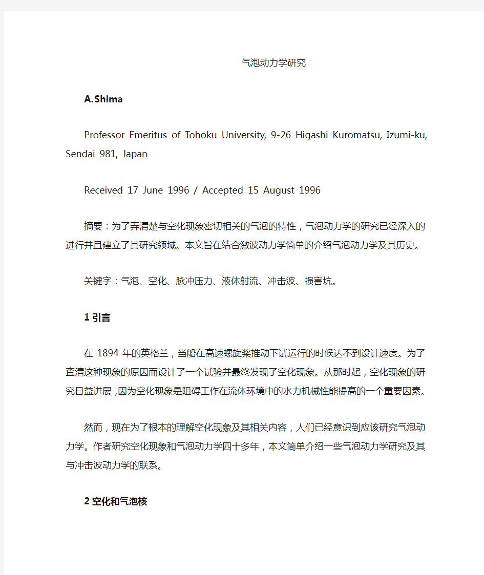
Rayleigh (1917)从理论上解决了这一难题并且得到了描述气泡运动的解析式。他的在无限的、非粘滞性的、不能压缩的液体中单个球形气泡运动公式如图示1所示。气泡的表面速
度V通过假定液体所做的功——当一个气泡由初始半径缩小到R——等于气泡运动的全部
动能获得。
图1,球形气泡
图2,气泡半径随着时间的变化(Plesset 1949)
是液体中无穷远处压力,为液体密度。综合从R=到(2)中的R=0,完全溃灭时间τ
近似下式:
此外,Plesset (1949)由连续方程和运动方程得到气泡运动方程。
P(R)是气泡表面压力,P(t)是液体压力,t是时间,,。他把
应用在旋转体表面的气泡中计算了R-t曲线。
通过比较解的结果和从高速摄影得到的结果,他确定除了气泡生长的初始阶段和气泡溃灭的最后阶段这两个结果都符合图2所示的曲线。
Poritsky (1952)第一个论述了液体粘性对气泡行为的影响。气泡在粘性液体中的运动由如下方程给出:
μ是液体粘性。
气泡的行为以无量纲的粘性μ来描述,定义为:
如果足够大,气泡的运动变得平滑。假如没有便面张力,溃灭时间变得无穷,即气泡
永不溃灭(Poritsky 1952)。Shima et al (1973)通过解(5)用数字得出粘性μ的作用延迟了气泡的溃灭。与此想法,表面张力σ减小了气泡溃灭时间τ。
4可压缩液体对气泡行为的影响
Gilmore (1952)从理论上阐明了可压缩液体对气泡运动的影响。Kirkwood-Bethe (1942)假设量
随着c+u的变化而变化从而得到了下面的球形气泡运动方程,其中c是液体中声速,u是质点速度h是液体的焓。
V=R是在气泡壁处液体声速,,是液体中无穷远处声速。
气泡壁处的焓定义为:
B≈300MPa, n≈7.0。
同样地,气泡壁处液体压强由下式给出。
是气泡壁内部气体或蒸汽向外的压强。
就|H|<<,把σ=0,μ=0带入(7),下面类似于不可压缩液体的方程可表示为:
在不可压缩液体中当R→0时V∞,可压缩液体中V∞。后者气泡溃灭速度明
显延缓。
Tomita and Shima (1977) and Shima and Tomita (1979)考虑到不可压缩液体的二阶项,应用PLK方法(钱永健1956)到由速度势得到的非线性波动方程,导出了气泡运动的下列方程。
是气泡内初始气压,γ是气泡内气体比热,ξ是液体体积粘度,∞是无限远处的值。
式(10)显示了气泡运动的大大衰减,原因是液体的可压缩性(Tomita and Shima
1977; Shima and Tomita 1979; Shima and Fujiwara 1980)。
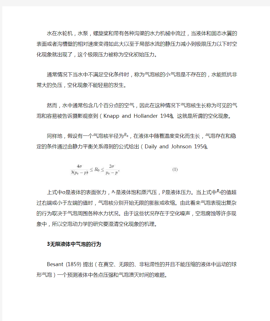
图3.气泡半径随着时间的变化:对照Shima-Fujiwara的解释和Lauterborn给出的实验值(Shima and Fujiwara 1980)。
图4.气泡半径随着时间的变化:对照Shima-Tomita的论论值与Lauterborn和Bolle的实验值(Shima and Tomita 1981)。
图5.气泡的半径随着时间的变化:对照Shima-Tomita的理论值和他们做的实验值(Shimaand Tomita 1981) 图3显示了硅油中气泡半径随着时间的变化,对比了Shima ,Fujiwara (1980)的理论结果和Lauterborn (1974)的实验结果。图中可以看出:在考虑了液体的可压缩性,理论解释和实验结果很相符,这种相符直到曲线的第二个反弹点处。
5实体壁处气泡的行为
注意到实际的空泡常出现在水轮机水翼,水泵,水泵水轮机和螺旋桨附近,联系到空化损害,许多调查者从理论上分析:气泡的溃灭在实体壁上或壁附近。气泡的行为和感应的冲压已经用数字表明(Rattray 1951; Shima 1968; 1971; Chapman and Plesset1972; Lauterborn and Bolle 1975; Nakajima and Shima 1977;Shima and Nakajima 1977; Shima and Sato 1979; Sato and Shima 1980; Shima and Sato 1980; Shima et al. 1981; Shimaand Sato 1981; Shima and Sato 1984; Dezhunov et al. 1980;Kuvshinov et al. 1982)。
图.6.L取不同值时的溃灭气泡周围流场的条纹摄影照片(Distance between the electrodes and a solidwall): 200,000 frames/s, Frame interval 5_s, Exposure 1_s/frame (Shima et al. 1981)
图.7.a,b.条纹照片a是气泡的初始时刻,b首次溃灭,L→∞,分辨率0.473~0.499 μs/mm,分辨方向从左至右(Shima et al. 1981)
图.8.最大冲击压Pmax和无量纲的距离L/Rmax 的关系(Shima at al. 1983)
图.9.气泡溃灭方式(Shima and Tomita 1987)
本节主要描述被某种程度的和实体壁隔离的球形气泡的溃灭。Rattray (1951) 和Shima (1968; 1971; 1968/1969a;1968/1969b)从理论上分析在实体壁附近的非粘滞、不可压缩液体中初始球形气泡的溃灭。另外,Shima and Tomita(1981)唯一地考虑了不可压缩液体的影响。
假定气泡的外形近似地满足球形对称,在气泡移动到距离实体壁比较远并不朝着它运动的情况下,Shima 和Tomita (1981)导出下面描述气泡运动的方程,这是第一次考虑到液体的可压缩性和实体壁的影响而修正的方程。
Po 是气泡内初始压强,Rmax是气泡最大半径,pr=R 液体在气泡壁处的压强,C∞液体中无穷远处的声速,L气泡中心和实心壁之间距离,Kvg水蒸气和不凝气混合物得比热。令L→∞,方程(11)就和Trilling (1952)得到的方程等同;令C∞→∞,就等同于Shima (1971)的方程。
图4,图5分别显示了方程(11)的R?t曲线和Lauterborn and Bolle (1975) 和Shima and Tomita
(1981)实验的对比结果。由图4可以看出实线的理论(Shima and Tomita 1981)曲线和实验结果符合得非常令人满意。图5中实验和理论在曲线的第二个转折前都很符合。
图.10.用铟制作的损害实例图案: Rmax = 5:1mm; (a) L=Rmax = 0:82, (b) 0:23; (c) 0:32 Dp:损害图案的平均直径(Tomita and Shima 1986)
图.11.实体壁处球形气泡的溃灭:Lauterborn-Bolle的实验值和来自Plesset-Chapman (Lauterborn-Bolle 1975)理论曲线的对比。
6实体壁对气泡行为的影响和气泡溃灭产生的冲击波
解释空蚀现象有两个理论。一种理论关于溃灭气泡产生的冲击压或冲击波(Hickling and Plesset 1964; Fujikawa and Akamatsu 1980)令一种理论关于气泡非球形溃灭时产生的液体射流(Kornfeld and Suvorov 1944; Naude and Ellis 1961; Plesset and Chapman 1971)。现在仍不知道这两种理论的正确性。
Shima et al. (1981)应用高速摄像机逐帧成像和图像延迟技术观察到了溃灭气泡的运动和
溃灭瞬间产生的冲击波。他们得到了下列结果。溃灭的气泡通常在再膨胀阶段产生球形冲击波,而无论气泡位于实体壁的何处。当气泡在实体壁近处溃灭时,冲击波的强度就弱很多。一个极端的情况:当气泡距离壁非常近时,就会出现非对称式溃灭,非对称溃灭产生多个波源,就会观察到复合冲击波。一个有趣的结果发现,喷射和冲击波在气泡膨胀到几乎碰到实体壁的一段非常短的时间间隔内同时存在。当气泡接触到实体壁溃灭,气泡在膨胀到极大时,形状如果是锐接触角的扁球形,射流对冲击力的贡献占主导;如果是钝接触角的扁球形,冲击波的贡献占主导,如图6,7。
7溃灭气泡产生的冲击压
Shima et al. (1983) 从对气泡高速摄影和测量实体壁附近由单个火花激发的气泡的溃灭产生的对壁的冲击压记录中到下列结论。(1)实体壁处的冲击压来源可分成三种类型,取决于
L/Rmax,L是电极和实体壁间距离,Rmax是气泡最大半径,如图8所示。
类型和他们存在的区域是:a)冲击波主导的区域L/Rmax ≤0.3且≥1.5;b)液体射流主导的区域0.6≤L/Rmax ≥0.8;c)冲击波和射流共存的区域0.3 ≤L/Rmax ≤0.6 且0.8
≤L/Rmax ≤1.5。
Tsuda et al. (1982)也发现了冲击波和液体射流共存的区域。
(2)气泡位置靠近或依附实体壁时对壁的冲击压更大。然而,为了澄清空化损害,知道气泡在各个位置存在的概率是必要的。
图.12.平面刚性边界附近气泡内部产生的射流阵列;Frame interval 2_s (Tomita and Shima 1990)
图.13.自由表面附近气泡的行为;Frame interval 10μs, Rmax = 0.61mm, L/Rmax = 2.61 (Tomita and Shima 1990)
8气泡溃灭和损害坑形成机制
气泡溃灭产生的冲击波和对物体产生的损害坑之间的关系已经被Tomita and Shima (1986)根据实验阐明。他们用火花产生气泡并观察气泡在一种软材料铟表面溃灭时产生的圆形损害坑图样
(1)气泡溃灭方式取决于它们接近实体壁的距离,如图9所示。图9中的点线指示了实体
壁影响的界限。第一个气泡溃灭的位置没有附着墙壁且离壁比较远,紧随的冲击压存在于非常短的时间段内:(i)压力脉冲在气泡溃灭期间;(ii)液体射流形成的冲击压在原始气泡内部;(iii)随着液体喷射压力向外的径流和收缩的气泡表面之间的交互
作用产生了许多瞬间气泡,他们溃灭从而产生冲击压(iV)环形原始气泡在它的反弹处(如图9)发出冲击波从而产生冲击压。
(2)气泡距实体壁非常近的时,首次溃灭和二次都产生强冲击压。
(3)火花产生的气泡溃灭时冲击压在铟表面的环形损伤图样,上面提到的(i), (ii) ,(iii)中
各种情况如图10所示。
图.14a,b。两个同相气泡的行为;帧间隔10μs (Tomita and Shima 1990)
图.15.液态氮中激光激发的空泡的行为;帧间隔10μs (Tsubota et al. 1996)
(4)作为小气泡和冲击波交互作用的结果,可能会出现局部高压,伴随着足够大的压力激增。
(5)附加空气泡和冲击波的交互作用导致损害坑。既然这样,坑群产生于液体射流冲击压。
然而,损害坑似乎是实体壁附近气泡溃灭引起的。
图.16.气泡半径随时间的变化(Tsubota et al. 1996)
9激光激发的空泡行为
当一束光强度超过液体电解质击穿阈值的激光聚焦透明液体中,光学击穿就出现了。然后就产生了气泡。Lauterborn(1974)发明了空化领域的这项技术。他还对照了激光在实体壁附近产生的气泡和Plesset and Chapman(1971)的分析结果,并且除了气泡溃灭的最后阶段(Lauterborn and Bolle
1975)都很相符。
图11展示了它们的对比。激光产生的气泡已经吸引了很多研究者而且这种有趣的气泡动力现象被给出了一个又一个解释(Teslenko 1980; Lauterborn 1982; Hentschel and
Lauterborn1982;Giovanneschi and Dufresne 1985; Sanada et al. 1987)
Tomita and Shima (1990)使用激光束聚焦成功制造了一个高球形度的理想气泡。各种不同条件下用激光产生的气泡被高速摄像机记录下来。图12,13,14展示了四种典型高速摄影相片。图12显示了实体壁附近气泡的第一次溃灭。在这种情况下,由于高惯性的液体射流从环形的溃灭的气泡被排除固体表面,气泡中就生成了两个涡环。
图13显示了自由表面附近气泡的运动。当气泡溃灭距离分界线相对较远时,自由表面轻微变形并且甚至在溃灭最后阶段都只产生很小的反作用力。在反弹阶段能观察到一次非常明显的液体射流。图14显示了两个气泡典型的例子。在图14(a)中,两个气泡几乎半径相同,lo = 3.72mm并且同相移动。这和一个中心距实体壁L = lo/2的气泡运动情况相同。
在图14(b)中,两个气泡半径不同,做异相运动。小气泡被它邻近的大气泡的压力场影响非常明显。小气泡溃灭并且它被大气泡排斥。
10气泡在低温液体中的行为
最近,低温流体被广泛的用于超导装置、核聚变等的冷却剂,这些液体高速流动,很容易变成气液两相,空化现象是一个需要解决的重要问题。低温液体中空化气泡运动被研究的有:当压力下降液体中气泡就生长并且气泡溃灭在低温冷却区(Hewitt and Parker 1968);激光引发的气泡在液氮中的动力学(Maeno et al. 1991);低温冷却液中气泡动力学(Tsubota and Shima 1993)。还有很未解决的问题需要澄清。
Tsubota et al. (1996)发明了用红宝石激光脉冲聚焦在液氮(一种典型的低温冷却液)中产
生近似球形气泡的技术,并且用高速摄影机成功观察了气泡的行为。图15中展示了一个观察的例子。图16显示了气泡半径随时间的变化。
图16,在室温下水中单个气泡的实验结果(Tomita and Shima 1990)和基于Rayleigh方法的解析结果的对照。发现,在液氮中气泡生长和溃灭时间比在水中长。
11结论
本文描述了大部分液体中单个气泡的动力学。阐明流场中多个气泡的动力学也是必要的。预计这部分气泡动力学特性将在将来研究。
参考文献:
BesantWH (1859) Hydrostatics and hydrodynamics. Art 158, Cambridge University Press, London.
Chapman R B, Plesset M S (1972) Nonlinear effect in the collapse of a nearly spherical cavity in a liquid, J. Basic Engng., Trans. ASME, Ser. D, 94: 142-146.
Daily J W, Johnson V E, Jr (1956) Turbulence and boundary-layer effects on cavitation inception from gas nuclei, Trans. ASME,78: 1695-1706.
Dezhkunov N Y, Kuvshinov V I, Kuvshinov G I, Prokhorenko P P(1980) A spherical collapse of a cavitation bubble between two solid walls, Sov. Phys. Acoust. 26: 392-395.
Fujikawa S, Akamatsu T (1980) Effects of the non-equilibrium condensation of vapour on the pressure wave produced by the collapse of a bubble in a liquid, J. Fluid Mech. 97: 481-512 Gilmore FR(1952) The collapse and growth of a spherical bubble in a viscous compressible liquid, Calif. Inst. of Tech. Hydrodynamics Lab. Rep. No. 26-4
Giovanneschi P, Dufresne D (1985) Experimental study of laserinduced cavitation bubbles, J. Appl. Phys. 58: 651-652
HentschelW, LauterbornW(1982) Acoustic emission of single laserproduced cavitation bubbles
and their dynamics, Appl. Sci. Res.38: 225-230
Hewitt H C, Parker J D (1968) Bubble growth and collapse in liquid nitrogen, J. Heat Transfer, Trans. ASME, 90: 22-26
Hickling R, Plesset MS (1964) Collapse and rebound of a spherical bubble in water, Phys. Fluids 7: 7-14
Kirkwood J G, Bethe H A (1942) The pressure wave produced by an underwater explosion, Of_ce Sci. Res. Dev. Rep. 588
KnappRT, HollanderA(1948) Laboratory investigation of the mechanism of cavitation, Trans. ASME, 70: 419-435
Kornfeld M, Suvorov L (1944) On the destructive action of cavitation, J. Appl.Phys. 15: 495-506 Kuvshinov G I, Prokhorenko P P, Dezhkunov N V, Kuvshinov V I(1982) Collapse of a cavitation bubble between two solid walls,Int. J. Heat Mass Transfer 25: 381-387
LauterbornW(1974) Kavitation durch laserlicht, Acustica 71: 51-78
Lauterborn W, Bolle H (1975) Experimental investigations of cavitation-bubble collapse in neighbourhood of a solid boundary, J.Fluid Mech. 72: 391-399
Lautterborn W (1982) Cavitation bubble dynamics-new tools for an intricate problem, Appl. Sci. Res. 38: 165-178
Maeno K, Yokoyama S, Hanaoka Y (1991) A study of laser-induced bubbles in cryogenic fluid (Behavior of bubbles in liquid nitrogen),J. Japan Soc. Aero. Space Sci. 39: 287-293 (in Japanese) Nakajima K, Shima A (1977) Analysis of the behavior of a bubble in a viscous incompressible liquid by _nite element method, Ing.-Arch., 46: 21-34
Naud_e C F, Ellis A T (1961) On the mechanism of cavitation damage by nonhemispherical cavities collapsing in contact with a solid boundary, J. Basic Engng., Trans. ASME, Ser. D, 83: 648-656
Plesset M S (1949) The dynamics of cavitation bubbles, J. Appl.Mech., 16: 227-282
Plesset M S, Chapman R B (1971) Collapse of an initially spherical vapor cavity in the neighborhood of a solid boundary, J. Fluid Mech. 47: 283-290
Poritsky H (1952) The collapse or growth of a spherical bubble or cavity in a viscous fluid, Proc. First Nat. Cong. in Appl. Mech.813-821
Rattray M, Jr (1951) Perturbation effects in cavitation bubble dynamics,Cal. Int. of Technol., Ph.
D. thesis
Rayleigh Lord (1917) On the pressure developed in a liquid during the collapse of a spherical cavity, Phil. Mag. 34: 94-98
Sanada N, Takayama K, Ikeuchi J (1987) An experimental study of the behavior of bubbles and shock waves generated by laser focusing in water, Trans. Japan Soc. Mech. Engineers, Ser.B
53-486: 317-325 (in Japanese)
Sato Y, Shima A (1980) The collapse of an initially spherical bubble near a solid wall, Rep. Inst. High Speed Mech., Tohoku Univ. 42:1-24
Shima A (1968/1969a) The behavior of a spherical bubble in the vicinity of a solid wall / Report 1, Rep. Inst. High Speed Mech.Tohoku Univ. 20: 83-108
Shima A (1968) The behavior of a spherical bubble in the vicinity of a solid wall, J. Basic Engng., Trans. ASME, Ser. D, 90: 75-89
Shima A (1968/1969b) The behavior of a spherical bubble in the vicinity of a solid wall / Report 3, Rep. Inst. High Speed Mech.,Tohoku Univ. 20: 213-236
Shima A (1971) The behavior of a spherical bubble in the vicinity of a solid wall / Report 4, Rep. Inst. High Speed Mech., TohokuUniv. 23: 195-220
Shima A, Miura N (1973) The behavior of a spherical bubble in mercury / Report 1, Rep. Inst. High Speed Mech., Tohoku Univ.28: 29-42
Shima A, Nakajima K (1977) The collapse of a non-hemispherical bubble attached to a solid wall, J. Fluid Mech. 80: 369-391
Shima A, Sato (1979) The collapse of a bubble attached to a solid wall, Ing.-Arch. 48: 85-95 Shima A, Tomita Y (1979) The behavior of a spherical bubble in mercury / Report 2, Rep. Inst. High Speed Mech., Tohoku Univ.39: 19-45
Shima A, Fujiwara T (1980) The collapse of bubbles in compressible hydraulic oils, J. Acoust. Soc. Am. 68: 1509-1515
Shima A, Sato Y (1980) The behavior of a bubble between narrow parallel plates, Z. angew Math. Phys. 31: 691-704
Shima A, Sato Y (1981) The collapse of a spheroidal bubble near a solid wall, J. de M_ecanique 20: 253-271
Shima A, Takayama K, Tomita Y, Miura N (1981) An experimental study on effects of a solid wall on the motion of bubbles and shock waves in bubble collapse, Acustica 48: 293-301
Shima A, Tomita Y (1981) The behavior of a spherical bubble near a solid wall in a compressible liquid, Ing.-Arch. 51: 243-255
Shima A, Takayama K, Tomita Y, Ohsawa N (1983) Mechanism of impact pressure generation from spark-generated bubble collapse near a wall, AIAA J 21: 55-59
Shima A, Sato Y (1984) The collapse of a bubble between narrow parallel plates (Case where a bubble is attached to a solid wall),Rep. Inst. High Speed Mech., Tohoku Univ. 49: 19-21
Shima A, Tomita Y(1987) Mechanism of impulsive pressure generation and damage pit formation by cavitation bubble collapse, J.Japan Soc. Mech. Engineers, 90-819: 164-169 (in Japanese) Teslenko V S (1980) Cavitation and inhomogeneities in underwater acoustics, edited by LauterbornW, Springer-Verlag, Berlin 30-34
Tomita Y, Shima A (1977) On the behavior of a spherical bubble and the impulse pressure in a viscous compressible liquid, Bulletin of the JSME, 20-149: 1453-1460
Tomita Y, Shima A(1986) Mechanisms of impulsive pressure generation and damage pit formation by bubble collapse, J. Fluid Mech.169: 535-564
Tomita Y, Shima A (1990) High-speed photographic observations of laser-induced cavitation bubbles in water, Acustica Journal, 71:161-171
Trilling L (1952) The collapse and rebound of a gas bubble, J. Appl.Phys. 23: 14-17
Tsien H S (1956) The Poincar_e-Lighthill-Kuo method, Advances in Appl. Mech. 4: 281-349 Tsubota M, Shima A(1993) Dynamics of bubbles in cryogenic fluids,ASME Cavitation and Multiphase Flow Forum 153: 133-136
Tsubota M, Tomita Y, Shima A, Kano I(1996) Dynamics of laserinduced bubble in pressurized liquid nitrogen, JSME International Journal Ser. B, 39-2: 257-263
Tsuda Y, Ueki H, Hirose T, Kimoto H(1982) Experimantal study of the shock generation at the collapse of cavitation bubble, Bulletin of the JSME 25-210: 1890-1897
气泡的声学特性分析
气泡的声学特性分析 2.2.1 气泡的散射特性 上世纪50年代后期,海洋学者开始意识到了气泡研究对于海洋探测的重要性,自从Urick 和Hoover 在1956年发现了气泡对于声波的散射后,气泡的散射问题就一直是水声研究领域的经典问题错误!未找到引用源。。目标对声信号的散射能力根据不同性质、大小、形状的目标而不同,同时也与声波的入射方向有关 [9]。因此,对于水声探测来说,目标散射场特性的研究尤为重要。沿x 轴方向传播的平面声波入射到半径为R 的软球边界上,观察点(,)S r θ处的声场。如图2.1所示,x 轴方向为零度方向。 ) ,(t x p i θ (,) S r θx R O 图2.1 平面声波在软球球面上的散射 入射平面声波表达式为: )cos (0)(0),(θωωkr t j kx t j i e p e p t x p --== (2-1) 其中,λ为波长,c 为介质声速,ω为角频率,λπω2==c k 为波数,),(θr 为点S 的球坐标。 根据波动方程和软球应满足的边界条件,球面上的声压为零,即 0 (r )i s R p p +== (2-2) 声场关于x 轴对称,所以取满足以x 轴对称的球坐标系的波动方程的解为 (2)0(cos )()j t s m m m m p R P h kr e ωθ∞==∑ (2-3) 其中,m R 为常数, )()2(x h m 为第二类m 阶汉克尔(Hankel )函数,为m 阶勒让德(Legendre)多项式,代表声波的传播方向为由球心向外。入射平面声波可以分解为球函数的和: ∑∞=+-=00)()(cos )12()(),,(m m m m t j i kr j P m j e p t r p θθω (2-4) 其中,)(kr j m 为m 阶球贝塞尔(Bessel )函数。将(2-2),(2-3)和(2-4)式合并,解出m a ,则s p 为:
气泡动力学研究
气泡动力学研究 A.Shima Professor Emeritus of Tohoku University, 9-26 Higashi Kuromatsu, Izumi-ku, Sendai 981, Japan Received 17 June 1996 / Accepted 15 August 1996 摘要:为了弄清楚与空化现象密切相关的气泡的特性,气泡动力学的研究已经深入的进行并且建立了其研究领域。本文旨在结合激波动力学简单的介绍气泡动力学及其历史。 关键字:气泡、空化、脉冲压力、液体射流、冲击波、损害坑。 1引言 在1894年的英格兰,当船在高速螺旋桨推动下试运行的时候达不到设计速度。为了查清这种现象的原因而设计了一个试验并最终发现了空化现象。从那时起,空化现象的研究日益进展,因为空化现象是阻碍工作在流体环境中的水力机械性能提高的一个重要因素。 然而,现在为了根本的理解空化现象及其相关内容,人们已经意识到应该研究气泡动力学。作者研究空化现象和气泡动力学四十多年,本文简单介绍一些气泡动力学研究及其与冲击波动力学的联系。 2空化和气泡核 水在水轮机,水泵,螺旋桨和带有各种沟渠的水力机械中流过,当液体和固态水翼的表面或者沟槽壁的相对速度变得如此大以至于局部水流的静压力减小到极限压力以下时空化现象就出现了,这个极限压力被称为空化初始压力。 通常情况下当水中不满足空化条件时,称为气泡核的小气泡是不存在的,水能抵抗非常大的负压,空化现象不能轻易的发生。 然而,水中通常包含几个百分点的空气,因此在这种情况下气泡核生长称为可见的气泡和容易被告诉摄影观察到(Knapp and Hollander 1948)。这就是所谓的空化现象。 同样地,假设有一个气泡核半径为,在液体中随着温度变化而生长,气泡存在和稳 定的条件通过由静力平衡关系得到的公式给出(Daily and Johnson 1956)。 上式中σ是液体的表面张力,是液体饱和蒸汽压,P是液体压力。当上式中的值超过右 端或小于左端的值时,气泡核分别开始无限的膨胀或收缩。由此看来气泡表现出复杂的行为取决于气泡周围各种水力状况。由于这些状况存在于空化噪声,空泡腐蚀等许多现象中,所以空泡动力学的研究要澄清空化现象的机理。 3无限液体中气泡的行为 Besant (1859) 提出(在真空、无限的、非粘滞性的并且不能压缩的液体中运动的球形气泡)一个预测液体中各点压强和气泡溃灭时间的难题。 Rayleigh (1917)从理论上解决了这一难题并且得到了描述气泡运动的解析式。他的在无限的、非粘滞性的、不能压缩的液体中单个球形气泡运动公式如图示1所示。气泡的表面速 度V通过假定液体所做的功——当一个气泡由初始半径缩小到R——等于气泡运动的全部 动能获得。
液体通流微小槽道内气泡动力学行为模拟_周吉
第62卷 第10期 化 工 学 报 V ol.62 N o.10 2011年10月 CIESC Jo urnal Oc to be r 2011研究论文液体通流微小槽道内气泡动力学行为模拟 周 吉,朱 恂,丁玉栋,王 宏,廖 强,谢 建 (重庆大学低品位能源利用技术及系统教育部重点实验室,重庆大学工程热物理研究所,重庆400044) 摘要:采用VO F方法,对液体通流微小通道内壁面逸出气泡的形成、生长及脱离运动进行了数值模拟,并讨论 了壁面浸润性、液体流速、气体流速对气泡动力学行为的影响。结果表明:气泡生长壁面亲水性增强有利于其 从壁面脱离;气泡生长壁面气相覆盖率随壁面接触角的增大而增大;流动阻力因子随壁面接触角的增大而减小。 较高的液体流速会导致气泡的脱离时间和脱离体积、壁面气相覆盖率及流动阻力因子减小;而较高的气体逸出 速率(气相Reynolds数高于14时)对气泡脱离体积、壁面气相覆盖率和流动阻力因子影响不大。 关键词:气泡;VO F方法;小槽道;动力特性;数值模拟 D OI:10.3969/j.issn.0438-1157.2011.10.010 中图分类号:T M911.4 文献标志码:A文章编号:0438-1157(2011)10-2740-07 N um erical sim ula tion of gas bu bble e mergin g fro m pore in to liquid flo w micro-ch an n el ZH OU Ji,ZHU Xu n,DING Yu dong,WAN G Hong,LIAO Qian g,XIE Jian (K ey L aboratory o f Low-grade Energ y Utilization Technologies and Sy stems, Institute o f Engineering Thermophysics,Chongqing University,Chongqing400044,China) Abstract:The dynam ic behavio r o f a gas bubble entering a liquid flow micro-channel through a pore w ith prescribed mass flow rate w as simulated by using computational fluid dynamics in co njunctio n w ith a volume of fluid(VOF)method.Sim ulations of the processes of gas bubble emergence,g row th, defo rmatio n and detachm ent w ere performed to ex plicitly track the evolutio n of the liquid-gas interface, and to characte rize the dy namics o f a gas bubble subjected to w ater flow in terms of departure v olume, flo w resistance coefficient,and g as coverage ratio.The effects of w ettability of the w all w here the bubble eme rges fro m,w ater and air mass flow rates w ere discussed w ith a particular focus on the effect o f the wettability of the bo ttom w all w hile the static contact ang les of the o ther channel w alls w ere set to90°. The simulated results sho wed that the hy dro philic w all facilita ted the departure of bubble w hile g as cove rage ratio increased and dimensionle ss flow resistance coefficient decreased fo r hydrophobic w all.High w ater inlet mass flow rate resulted in an ea rlier departure and decreased departure vo lum e of the bubble as well as low gas coverage ratio and flow resistance coefficient.I t w as found that increasing air mass flo w rate led to earlie r detachm ent of the bubble.H ow eve r,hig her air m ass flow ra te show ed scarce influence on the dy namic behavior of the bubble o nce the Rey nolds number of air w as over14. Key words:bubble;vo lume of fluid method;mini-channel;dynamics;numerical simulation 2011-01-10收到初稿,2011-04-28收到修改稿。 联系人:朱恂。第一作者:周吉(1986—),男。 基金项目:国家自然科学基金项目(50876119);重庆市自然科学基金项目(CS TC,2009BB6212);教育部新世纪优秀人才支持计划项目(NCE T-07-0912)。 Received date:2011-01-10. Correspon ding author:Prof.ZH U Xun,zhu xun@https://www.360docs.net/doc/759573976.html, Foun dation item:supported by the National Natural S cience Foundation of China(50876119),the Natural S cience Foundation of Ch ong qin g(CS TC,2009BB6212)and th e Prog ram for New Century Excellent T alents in University(NCET-07-0912).
初始形状对浮升气泡动力特性的影响
第45卷 第1期 西 安 交 通 大 学 学 报 Vol.45 No1 2011年1月 JO U R N A L O F X I ’A N JI A O TO N G U N I V ER SI TY Jan.2011 收稿日期:2010-06-17. 作者简介: 何丹(1986-),女,硕士生;李彦鹏(联系人),男,教授. 基金项目:国家自然科学基DOI: 初始形状对浮升气泡动力特性的影响 何丹,李彦鹏,刘艳艳 (长安大学环境科学与工程学院,710064, 西安) 摘要:采用Level Set 方法, 三维直接数值模拟了浮力作用下单个气泡的上升运动. 数值模拟中, 气液系统的物性参数设置为埃奥特沃斯数Eo =1~103, 莫顿数Mo =10-10~102 . 数值研究了气泡的初始形状对气泡的变形和上升速度的影响,并与文献中结果进行了比较; 给出了高Eo 时气泡由球帽状转变为气泡环的结构相图, 确定了二者形状转变的Eo 和Mo ; 最后详细分析了初始形状影响气泡动力学特性的机理. 模拟结果表明:低Eo (Eo <52)时浮升气泡的终端形状与上升速度基本不受初始形状的影响; 高Eo 和低Mo 时的浮升气泡受初始形状的支配, 呈现出球帽状和气泡环两种最终形状, 初始气泡的高宽比越大, 气泡越容易变形为气泡环, 上升速度的脉动也越剧烈. 关键词:浮升气泡;初始形状;相图;数值模拟 中图分类号:TK124 文献标志码:A 文章编号:0253-987X(2011)01-0000-00 Effect of Initial Bubble Shape on Dynamics of a Buoyancy-driven Bubble HE Dan, LI Yanpeng, LIU Yanyan (College of Envi r onm ent al Sci ence and Engi neer i ng, C hang’A n U ni ver s i t y, X i ’an 710064, China) Abstract :Three-dimensional direct numerical simulation on a single bubble rising by buoyancy in viscous liquids was carried out with the level set method. The effect of initial bubble shape on the bubble dynamics was studied numerically w i t h E?t v?s num ber (Eo : O (0)-O (3)) and Morton number (Mo :O (-10)-O (2)) , and the influencing mechanism was explained in detail. The bubble shape and rise velocity predicted by the simulation agree with a well-known bubble regime phase diagram in literature. In addition, a phase map was also established at high Eo to provide quantitative analysis on the transition of final bubble topology from spherical-cap to toroidal bubble. The numerical results show that the final shape and rise velocity are not affected by the initial bubble shape at low Eo (Eo <52), while the final bubble state appears to be the spherical-cap and toroidal bubble and is influenced by initial bubble shape at high Eo and low Mo . The bubble is easier to become a toroidal bubble and the temporal fluctuation of bubble rise velocity is stronger when the aspect ratio of the initial bubble is greater. Keywords :buoyancy-driven bubble ;initial shape ;phase diagram; numerical simulation 以气泡为分散相的气液两相流动存在于许多工业过程中,如能源与化学工业的鼓泡床反应过程、污水处理中的曝气工艺、湖泊河道治理中的受氧过程等,都需要考虑气泡传质问题,而这一问题与气泡的动力学行为密切相关。因此,深入认识气泡的动力学行为对于改进实际工业过程具有重要的理论意义。 Bhaga 等[1]系统地研究了浮力气泡在黏性液体中的上升运动,得到了描述气泡形状及终端上升速度与3个参数(雷诺数Re 、莫顿数Mo 和埃奥特沃斯数Eo )之间关系的气泡相图。随后30年,各国学者一方面利用高速摄影技术,另一方面采用基于界面捕捉的数值模拟技术,对气泡在各种局部流动条件以及不同水质下的动力学特性 CNKI:61-1069/T_20101019.2211.014
气泡动力学
Computational Fluid Dynamics (CFD)Modeling of Bubble Dynamics in the Aluminum Smelting Process Kaiyu Zhang,?,?Yuqing Feng,*,?Phil Schwarz,?Zhaowen Wang,?and Mark Cooksey § ?School of Metallurgical Engineering,Northeastern University,Shenyang,China ?CSIRO Mathematics,Informatics and Statistics,Clayton,Victoria 3169,Australia §CSIRO Process Science and Engineering,Clayton,Victoria 3169,Australia The Hall ?He r oult process is the only commercial process for producing aluminum from alumina.1In an aluminum reduction cell,alumina is fed to,and dissolved in,a molten bath of cryolite at approximately 970°C in which several carbon anodes are submerged.Electric current is fed between the anodes and an underlying cathode to cause electrochemical reduction of the alumina reactant to aluminum which settles onto a pool lying over the cathode.CO 2gas bubbles are generated by the reaction at the anode,which causes recirculation ?ows as a result of the gas bubbles moving up through the molten cryolite (the bath)under the in ?uence of buoyancy.Because cryolite will dissolve most potential wall materials,a layer of frozen cryolite must be formed on the walls of the vessel to contain the bath,and this requires the achievement of a delicate heat balance in the cell,over which the recirculatory ?ows in the bath have an important in ?uence.The gases are generated at the bottom surface of the anodes in a continuous manner.Thus,the anode bottom surfaces are covered with a layer of bubbles right beneath the anode bottom surface.The bubble area coverage can vary from 30to 90%,2?4which leads to an extra voltage drop.According to Haupin,5the extra voltage drop in the electrolyte due to the presence of gas bubbles is in the range 0.15?0.35V.The bubble motion beneath the anodes also introduces waves into the bath ?metal interface,voltage ?uctuations,and high local current density, and indirectly results in instabilities of the magnetic ?eld.Moreover,the global scale bath ?ow and alumina mixing are closely related to the bubble behavior.Therefore,a detailed understanding of the bubble dynamics and the resulting bath ?ow is important to quantitatively assess its e ?ect on cell performance.molten salt bath)restricts direct observation of bubble behavior in industrial cells.Studies of bubble behavior in industrial cells,laboratory cells,and physical models have been reviewed by Cooksey et al.6There is good evidence that the bubble layer thickness is at least 5mm in industrial cells,5and similar in laboratory cells.6?8In order to observe the bubble dynamic behavior at a scale typical of industrial cell geometries,room temperature laboratory models have been used.9?28Trans-parent materials such as Plexiglas are used to construct the cell, and a room temperature liquid is used to replace the cryolite bath.As listed in Table 1,various gas ?liquid systems have been used to represent the CO 2?cryolite system,such as NaOH solution,9CuSO 4solution,10air ?oil ?water,11or simply air ? water.12?28Since the bubble formation is quite complex and the motion is controlled by many factors,such as surface tension,contact angle,anode shape,and even the roughness of the surface,none of those systems can closely match all the factors of the real system.The standpoint for using the air ?water system is that the kinematic viscosity of water is very similar to that of cryolite (1.005×10?6m 2s ?1for water and 1.43×10?6m 2s ?1for cryolite).This will lead to a similar liquid ?ow dynamics as long as the same volume of gas is used but might not have relevance on the similarity of bubble dynamics.Special Issue:Multiscale Structures and Systems in Process Engineering Received:December 15,2012 Revised:May 7,2013 Accepted:May 7,2013 Published:May 7,2013