脱硫塔设计计算
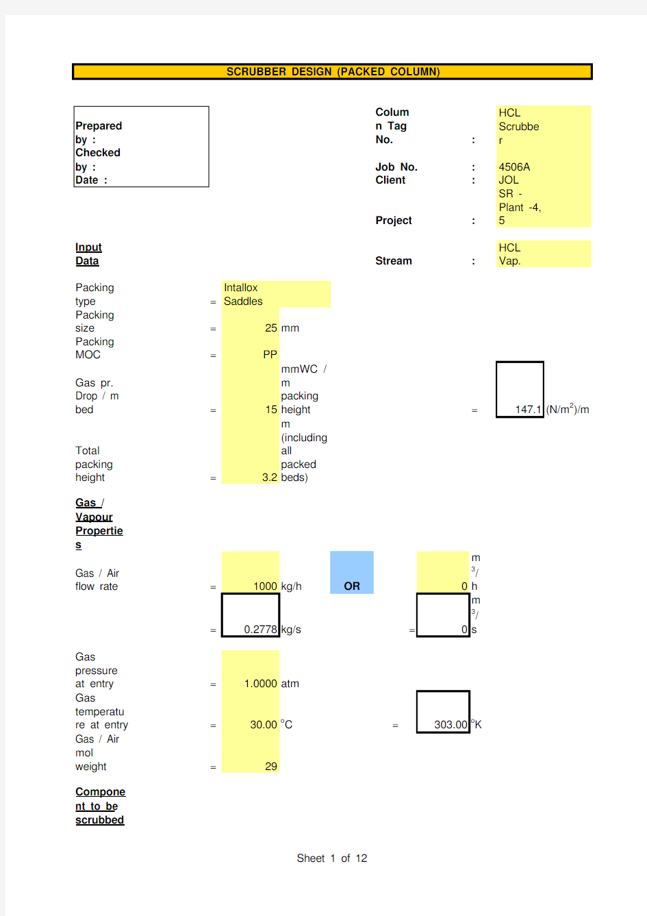
Colum
n Tag
No.:HCL Scrubbe r
Job No.:4506A Client:JOL
Project:SR -Plant -4, 5
Input
Data Stream:HCL Vap.
Packing
type=Intallox Saddles
Packing
size=25mm Packing
MOC=PP
Gas pr.
Drop / m
bed=15mmWC /
m
packing
height=147.1(N/m2)/m
Total
packing
height= 3.2m (including all packed beds)
Gas / Vapour Propertie s
Gas / Air
flow rate=1000kg/h OR0m 3/ h
=0.2778kg/s=0m 3/ s
Gas
pressure
at entry= 1.0000atm
Gas
temperatu
re at entry=30.00o C=303.00o K Gas / Air
mol
weight=29
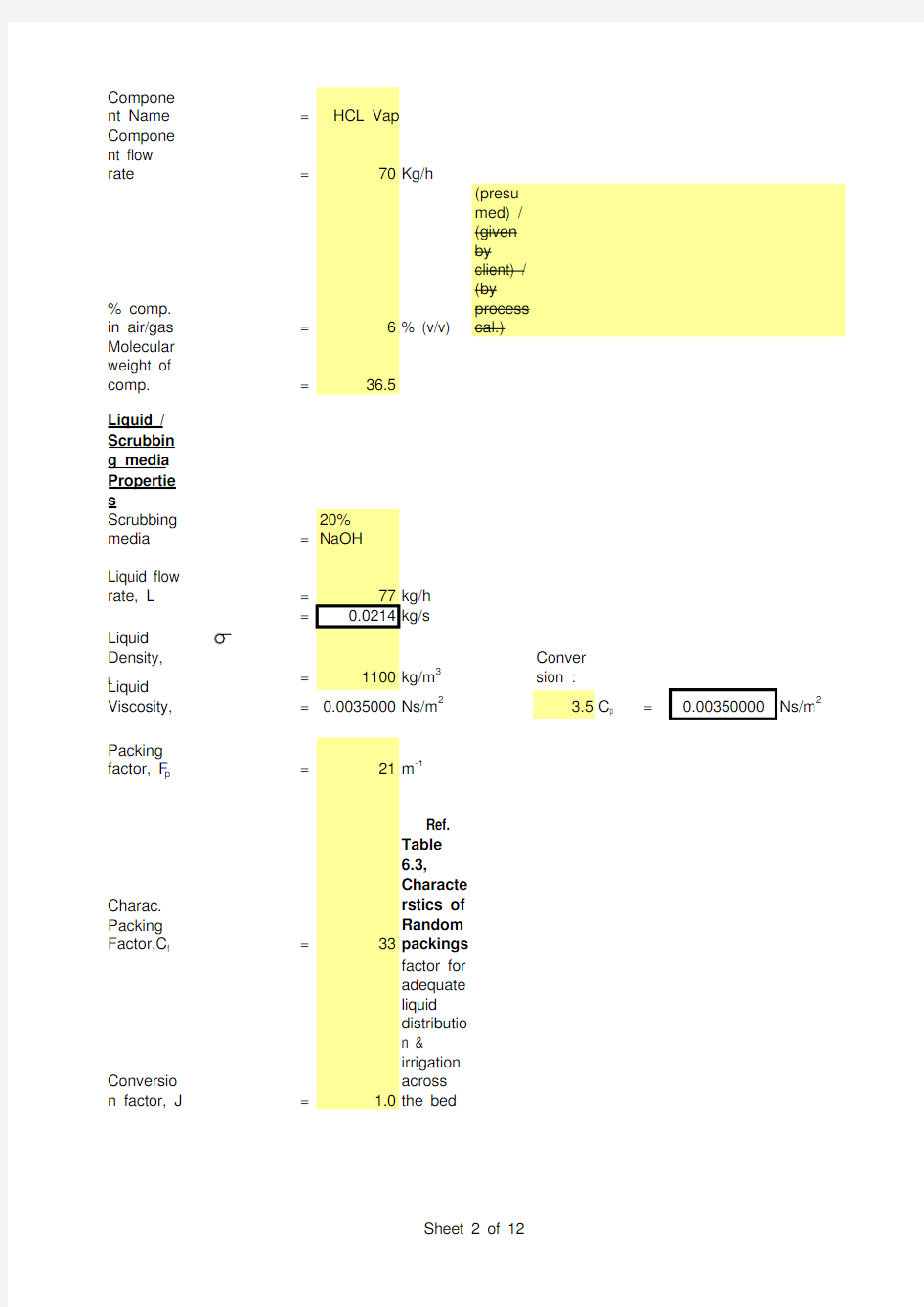
Compone
nt to be
scrubbed
SCRUBBER DESIGN (PACKED COLUMN)
nt Name=HCL Vap Compone
nt flow
rate=70Kg/h % comp.
in air/gas=6% (v/v)
Molecular
weight of
comp.=36.5
Liquid /
Scrubbin
g media
Propertie
s
Scrubbing
media=20% NaOH
Liquid flow
rate, L
=77kg/h =0.0214kg/s
Liquid Density,
L =1100kg/m3
Conver
sion :
Liquid
Viscosity,=0.0035000Ns/m2 3.5C p =Ns/m2 Packing
factor, F p=21m-1
Charac.
Packing
Factor,C f=33 Ref. Table 6.3, Characte rstics of Random packings
Conversio
n factor, J= 1.0factor for
adequate
liquid
distributio
n &
irrigation
across
the bed
0.00350000
ons
TO CALCULATE COLUMN DIAMETER Since
larger flow
quantities
are at the
bottom for
an
absorber,
the
diameter
will be
chosen to
accommo
date the
bottom
conditions
.
To
calculate
Gas
density
Avg.
molecular
weight=29.45Kg / Kmol
Select vol.
flow rate
and mass
flow rate
from
above,
Selected
mass flow
rate=0.277778Kg/s Selected
vol. Flow
rate=0.234499m3/s Selected
molar flow
rate=0.009432Kmol/s
Therefore
, gas
density= 1.1846Kg/m3(mass flow rate / vol. Flow rate)
To find
L', G' and Tower c/s area Assuming essentially complete absorbtion ,
Compone nt
removed=0.0207
Kg/s
(molar
flow
rate x %
comp. x
mol.
Wt.)
Liquid
leaving=0.0420Kg/s (Inlet liquid flow rate + comp. Remov ed)
0.5=
Using0.00497
a
s
or
di
n
at
e,
Refer
fig.6.34
using a
gas
pressure
drop of147.1(N/m2)/m G' 2 C f
μL0.1 J=0.04
(from
graph)
- G) g c
Therefore,
G'=0.5
L
J
= 1.6665Kg / m2.s
Tower c/s
area=0.1667m2
( c/s
area =
mass
flow
rate / G'
)
Tower
diameter=0.4607m=460.7mm
=500mm
Correspon
ding c/s
area=0.1963m2
TO ESTIMATE POWER REQUIREMENT
Efficiency
of fan /
blower=60%
To
calculate
pressure
drop
Pressure
drop for
irrigated=470.72N/m2(pressu re drop per m packing
x total
ht. of
packing
)
packing
For dry
packing,
O/L Gas
flow rate,
G'=2.s
(Gas
inlet
flow
rate -
Compo
nent
remove
d) / c/s
area
O/L Gas
pressure=2
(subtra
cting
pressur
e drop
across
packing
)
Gas
density,
G
=
gas o/l
pr.
kelvin101330
= 1.1605Kg/m3
C D=96.7
Ref.
Table
6.3,
Characte
rstics of
Random
packings
Delta P =
Z
=
2
Pressure drop for packing
=
613.61N/m 2
(irrigate d
packing + dry packing )Pressure drop for internals
=25mmWC (packin g
support s and liquid distribut ors)
=245.17N/m 2
Gas velocity =
7.5m/s
Inlet
expansion & outlet = 1.5 x Velocity heads =
1.5 x (V 2 / 2g)
contractio n losses
=
42.19N m / Kg
=
49.97N/m 2
(divide by
density)
Total pressure drop
=
908.75N/m 2
(packin g +internal s +losses)
Fan power output
=pressure drop,N/m 2x (gas in -componen t removed)Kg/s
O/L gas density,3
=Power for fan motor
=0.34kW
(fan power output /motor efficien cy)
=0.45hp
Liq.-Vap.Flow
factor, F LV
=(L / V) x (V / L )=0.0025
Design for
an initial pressure drop of 15
mm H2O /m packing
From K 4v/s F LV ,K 4=
0.85
K 4 at flooding
= 6.50
Trial %flooding
=( (K 4 /K 4 at flooding)) x 100=36.1620
Gas mass flow rate,V m
= 13.1 F p (μL / L )0.1=
3.7763kg/m 2.s
Trial column c/s area =V / V m
(Trial A s )
=
0.0736m 2
Trial column dia., D
=0.3060m
D = (4/pi) x Trial A s
Round off 'D' to nearest standard size
Therefore,D
=0.500m
COLUMN DIAMETER / HYDRAULIC CHECK
(1/2)
Column C/S area,
A s=0.1963
m2A s =
(pi/4) x
D2
% flooding=% flooding = Trial % flooding x (Trial A s / A s)
Conclusi on Generally packed towers are designed for 50% --85% flooding. If flooding is to be reduced, (i) Select larger packing size and repeat the above steps.
OR
(ii) Increase the column diameter and repeat the above steps.
Norton's Correlati on :
ln HETP = n -0.187 ln + 0.213 ln μ
Applicable when,liquid phase surface tension >4 dyne/cm & < 36dyne/cm liquid viscosity > 0.08 cP & < 0.83cP
Conver sion :
Input Data 0.018 N/m =
dyne/cm
Liquid-phase Surface Tension,=
20dyne/cm Liquid Viscosity = 3.5
cP n
=
1.13080
Calculati on ln HETP =HETP
= 2.310437ft =
0.704221m
HETP PREDICTION
Norton's Correlation Applicable
Norton's Correlation NOT applicable
18
For
separation
s, less
than 15
theoritical
stages, a
20%
design
safety
factor can
be
applied.
Consideri
ng 20%
safety
factor,
HETP=
For
separation
s,
requiring
15 to 25
theoritical
stages, a
15%
design
safety
factor can
be
applied.
Consideri
ng 15%
safety
factor,
HETP=0.809854m