中英文文献翻译—汽车制动系统的概述

附录
Automobile Brake System
The braking system is the most important system in cars. If the brakes fail, the result can be disastrous. Brakes are actually energy conversion devices, which convert the kinetic energy (momentum) of the vehicle into thermal energy (heat).When stepping on the brakes, the driver commands a stopping force ten times as powerful as the force that puts the car in motion. The braking system can exert thousands of pounds of pressure on each of the four brakes.
Two complete independent braking systems are used on the car. They are the service brake and the parking brake.
The service brake acts to slow, stop, or hold the vehicle during normal driving. They are foot-operated by the driver depressing and releasing the brake pedal. The primary
purpose of the brake is to hold the vehicle stationary while it is unattended. The parking brake is mechanically operated by when a separate parking brake foot pedal or hand lever is set.
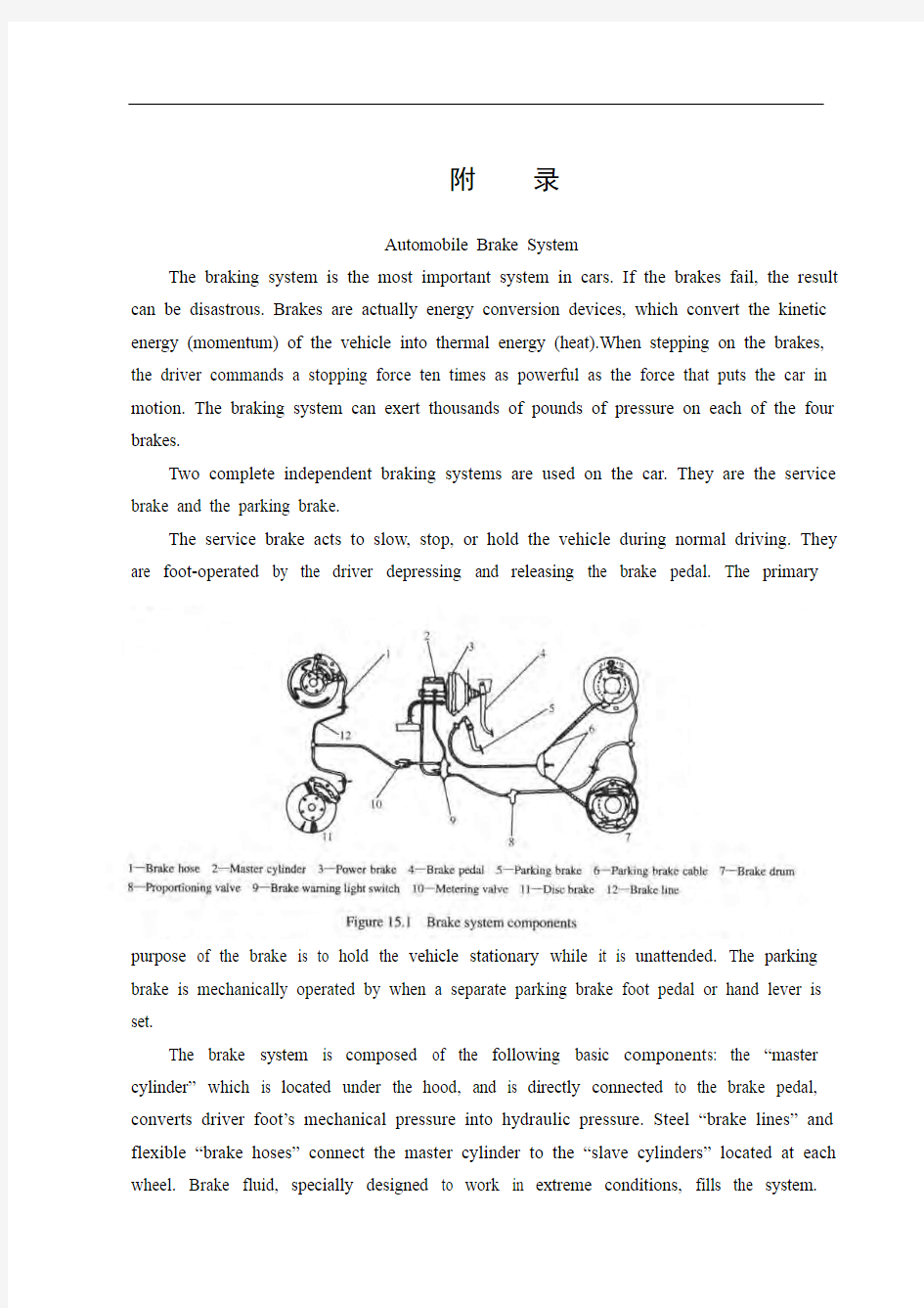
The brake system is composed of the following basic component s: the “master cylinder” which is located under the hood, and is directly connected to the brake pedal, converts driver foot’s mechanical pressure into hydraulic pressure. Steel “brake lines” and flexible “brake hoses” connect the master cylinder to the “slave cylinders” located at each wheel. Brake fluid, specially designed to work in extreme conditions, fills the system.
“Shoes” and “pads” are pushed by the slave cylinders to contact the “drums” and “rotors” thus causing drag, which (hopefully) slows the car.
The typical brake system consists of disk brakes in front and either disk or drum brakes in the rear connected by a system of tubes and hoses that link the brake at each wheel to the master cylinder (Figure).
Basically, all car brakes are friction brakes. When the driver applies the brake, the control device forces brake shoes, or pads, against the rotating brake drum or disks at wheel. Friction between the shoes or pads and the drums or disks then slows or stops the wheel so that the car is braked.
In most modern brake systems (see Figure 15.1), there is a fluid-filled cylinder, called master cylinder, which contains two separate sections, there is a piston in each section and both pistons are connected to a brake pedal in the driver’s compartment. Wh en the brake is pushed down, brake fluid is sent from the master cylinder to the wheels. At the wheels, the fluid pushes shoes, or pads, against revolving drums or disks. The friction between the stationary shoes, or pads, and the revolving drums or disks slows and stops them. This slows or stops the revolving wheels, which, in turn, slow or stop the car.
The brake fluid reservoir is on top of the master cylinder. Most cars today have a transparent r reservoir so that you can see the level without opening the cover. The brake fluid level will drop slightly as the brake pads wear. This is a normal condition and no cause for concern. If the level drops noticeably over a short period of time or goes down to about two thirds full, have your brakes checked as soon as possible. Keep the reservoir covered except for the amount of time you need to fill it and never leave a cam of brake fluid uncovered. Brake fluid must maintain a very high boiling point. Exposure to air will cause the fluid to absorb moisture which will lower that boiling point.
The brake fluid travels from the master cylinder to the wheels through a series of steel tubes and reinforced rubber hoses. Rubber hoses are only used in places that require flexibility, such as at the front wheels, which move up and down as well as steer. The rest of the system uses non-corrosive seamless steel tubing with special fittings at all attachment points. If a steel line requires a repair, the best procedure is to replace the compete line. If this is not practical, a line can be repaired using special splice fittings that are made for brake system repair. You must never use copper tubing to repair a brake system. They are dangerous and illegal.
Drum brakes, it consists of the brake drum, an expander, pull back springs, a stationary back plate, two shoes with friction linings, and anchor pins. The stationary back plate is secured to the flange of the axle housing or to the steering knuckle. The brake drum is mounted on the wheel hub. There is a clearance between the inner surface of the drum and the shoe lining. To apply brakes, the driver pushes pedal, the expander expands the shoes and presses them to the drum. Friction between the brake drum and the friction linings brakes the wheels and the vehicle stops. To release brakes, the driver release the pedal, the pull back spring retracts the shoes thus permitting free rotation of the wheels.
Disk brakes, it has a metal disk instead of a drum. A flat shoe, or disk-brake pad, is located on each side of the disk. The shoes squeeze the rotating disk to stop the car. Fluid from the master cylinder forces the pistons to move in, toward the disk. This action pushes the friction pads tightly against the disk. The friction between the shoes and disk slows and stops it. This provides the braking action. Pistons are made of either plastic or metal. There are three general types of disk brakes. They are the floating-caliper type, the fixed-caliper type, and the sliding-caliper type. Floating-caliper and sliding-caliper disk brakes use a single piston. Fixed-caliper disk brakes have either two or four pistons.
The brake system assemblies are actuated by mechanical, hydraulic or pneumatic devices. The mechanical leverage is used in the parking brakes fitted in all automobile. When the brake pedal is depressed, the rod pushes the piston of brake master cylinder which presses the fluid. The fluid flows through the pipelines to the power brake unit and then to the wheel cylinder. The fluid pressure expands the cylinder pistons thus pressing the shoes to the drum or disk. If the pedal is released, the piston returns to the initial position, the pull back springs retract the shoes, the fluid is forced back to the master cylinder and braking ceases.
The primary purpose of the parking brake is to hold the vehicle stationary while it is unattended. The parking brake is mechanically operated by the driver when a separate parking braking hand lever is set. The hand brake is normally used when the car has already stopped. A lever is pulled and the rear brakes are approached and locked in the “on” position. The car may now be left without fear of its rolling away. When the driver wants to move the car again, he must press a button before the lever can be released. The hand brake must also be able to stop the car in the event of the foot brake failing. For this reason, it is separate from the foot brake uses cable or rods instead of the hydraulic system.
Anti-lock Brake System
Anti-lock brake systems make braking safer and more convenient, Anti-lock brake systems modulate brake system hydraulic pressure to prevent the brakes from locking and the tires from skidding on slippery pavement or during a panic stop.
Anti-lock brake systems have been used on aircraft for years, and some domestic car were offered with an early form of anti-lock braking in late 1990’s. Recently, several automakers have introduced more sophisticated anti-lock system. Investigations in Europe, where anti-lock braking systems have been available for a decade, have led one manufacture to state that the number of traffic accidents could be reduced by seven and a half percent if all cars had anti-lock brakes. So some sources predict that all cars will offer anti-lock brakes to improve the safety of the car.
Anti-lock systems modulate brake application force several times per second to hold the tires at a controlled amount of slip; all systems accomplish this in basically the same way. One or more speed sensors generate alternating current signal whose frequency increases with the wheel rotational speed. An electronic control unit continuously monitors these signals and if the frequency of a signal drops too rapidly indicating that a wheel is about to lock, the control unit instructs a modulating device to reduce hydraulic pressure to the brake at the affected wheel. When sensor signals indicate the wheel is again rotating normally, the control unit allows increased hydraulic pressure to the brake. This release-apply cycle occurs several time per second to “pump” the brakes like a driver might but at a much faster rate.
In addition to their basic operation, anti-lock systems have two other things in common. First, they do not operate until the brakes are applied with enough force to lock or nearly lock a wheel. At all other times, the system stands ready to function but does not interfere with normal braking. Second, if the anti-lock system fail in any way, the brakes continue to operate without anti-lock capability. A warning light on the instrument panel alerts the driver when a problem exists in the anti-lock system.
The current Bosch component Anti-lock Braking System (ABSⅡ), is a second generation design wildly used by European automakers such as BWM, Mercedes-Benz and Porsche. ABSⅡsystem consists of : four wheel speed sensor, electronic control unit and modulator assembly.
A speed sensor is fitted at each wheel sends signals about wheel rotation to control unit.
Each speed sensor consists of a sensor unit and a gear wheel. The front sensor mounts to the steering knuckle and its gear wheel is pressed onto the stub axle that rotates with the wheel. The rear sensor mounts the rear suspension member and its gear wheel is pressed onto the axle. The sensor itself is a winding with a magnetic core. The core creates a magnetic field around the winding, and as the teeth of the gear wheel move through this field, an alternating current is induced in the winding. The control unit monitors the rate o change in this frequency to determine impending brake lockup.
The control unit’s function can be divided into three parts: signal processing, logic and safety circuitry. The signal processing section is the converter that receives the alternating current signals form the speed sensors and converts them into digital form for the logic section. The logic section then analyzes the digitized signals to calculate any brake pressure changes needed. If impending lockup is sensed, the logic section sends commands to the modulator assembly.
Modulator assembly
The hydraulic modulator assembly regulates pressure to the wheel brakes when it receives commands from the control utuit. The modulator assembly can maintain or reduce pressure over the level it receives from the master cylinder, it also can never apply the brakes by itself. The modulator assembly consists of three high-speed electric solenoid valves, two fluid reservoirs and a turn delivery pump equipped with inlet and outlet check valves. The modulator electrical connector and controlling relays are concealed under a plastic cover of the assembly.
Each front wheel is served by electric solenoid valve modulated independently by the control unit. The rear brakes are served by a single solenoid valve and modulated together using the select-low principle. During anti-braking system operation, the control unit cycles the solenoid valves to either hold or release pressure the brake lines. When pressure is released from the brake lines during anti-braking operation, it is routed to a fluid reservoir. There is one reservoir for the front brake circuit. The reservoirs are low-pressure accumulators that store fluid under slight spring pressure until the return delivery pump can return the fluid through the brake lines to the master cylinder.
汽车制动系统
制动系统是汽车中最重要的系统。如果制动失灵,结果可能是损失惨重的。制动器实际就是能量转换装置,它将汽车的动能(动量)转化成热能(热量)。当驾驶员踩下制动踏板,所产生的制动力是汽车运动时动力的10倍。制动系统能对四个刹车系统中的每个施加数千磅的力。
每辆汽车上使用两个完全独立的制动系统,即行车制动器和驻车制动器。
行车制动器起到减速、停车、或保持车辆正常行驶。制动器是由司机用脚踩、松制动器踏板来控制的。驻车制动器的主要作用就是当车内无人的时候,汽车能够保持静止。当独立的驻车制动器—踏板或手杆,被安装时,驻车制动器就会被机械地操作。
制动系统是由下列基本的成分组成:位于发动机罩下方,而且直接地被连接到制动踏板的“制动主缸”把驾驶员脚的机械力转变为液压力。钢制的“制动管路”和有柔性的“制动软管”把制动主缸连接到每个轮子的“制动轮缸”上。制动液, 特别地设计为的是工作在极端的情况,填充在系统中。“制动盘”和“衬块”是被制动轮缸推动接触“圆盘”和“回转体”如此引起缓慢的拖拉运动, (希望)使汽车减慢速度。
典型的制动系统布置有前后盘式,前盘后鼓式,各个车轮上的制动器通过一套管路系统连接到制动主缸上。
基本上讲,所有的汽车制动器都是摩擦制动器。当司机刹车时,控制装置会迫使制动蹄,或制动衬片与车轮处的旋转的制动鼓或制动盘接触。接触后产生的摩擦使车轮转动减慢或停止,这就是汽车的制动。
在最基本的制动系统中,有一个制动主缸,这个主缸内部填充制动液,并包含两个部分,每个部分里都有一个活塞,两个活塞都连接驾驶室里的制动踏板。当制动踏板被踩下时,制动液会从制动主缸流入轮缸。在轮缸中,制动液推动制动蹄或制动衬片与旋转的制动鼓或制动盘接触。静止的制动蹄或制动衬片与旋转的制动鼓或制动盘之间产生摩擦力使汽车的运动逐渐减缓或停止。
制动液的装置位于主缸的顶部。目前大多数的车都有一个容易看见的装制动液的装置,为的是不用打开盖子就可以看得见制动液的油面。随着制动踏板的运动制动液就会缓慢的下降,正常情况下是这样的。如果制动液在很短的时间内下降得明显或者下降了三分之二,那么就要尽快的检查你的制动系统了。保持制动液装置充满制动液除非你需要维修它,制动液必须保持很高的沸点。位于在空气中的制动液就会吸收空气中的潮气引起制动液低于沸点。
制动液通过一系列的管路从主缸到达各车轮。橡胶软管只用在需要弹力的地方,
比如应用在前轮。在车的行进中上下来回运动。系统的其它部分在所有的连接点上都应用了无腐蚀性的无缝钢管。如果钢线需要修理的话,最好的方法就是代替这条线。如果这不符合实际,那么为了制动系统可以用特殊的装置修理它。你不可以用铜管来修理制动系。它们是危险也是不正确的。
鼓式制动器包括制动鼓,一个轮缸,回拉弹簧,一个制动底版,两个带摩擦层的制动蹄。制动底版固定在轮轴外部的法兰或转向节。制动鼓固定在轮毂上。制动鼓的内部表面与制动蹄的内层之间有空隙。要使用制动器时,司机就要踩下踏板,这时轮缸扩大制动片,对其施加压力,是制动蹄触碰制动鼓。制动鼓与摩擦片之间产生的摩擦制动了车轮,从而使汽车停止。要释放制动器时,司机松开踏板,回拉弹簧拉回制动片,这样车轮会自由转动。
盘式制动器包括制动盘而不是鼓,在它的两面上各有一个薄的制动片或叫盘式制动器的制动片。制动片是靠挤住旋转的制动盘来停住汽车。制动主缸里流出的制动液迫使活塞向里部的金属盘移动,这便使摩擦片紧紧地贴住制动盘。这时制动片与制动盘产生的摩擦使汽车减速、停止,出现了制动行为。活塞分金属或塑料。盘式制动器主要有三种,即:浮动卡钳型、固定卡钳型和滑动卡钳型。浮动卡钳型和滑动卡钳型盘式制动器使用单活塞。固定卡钳型盘式制动器既可以使用两个活塞有可以使用四个活塞。
制动系统是由机械能,液压能或气压能装置驱动的。在机械杠杆适合所有的汽车的驻车制动器中使用。当踩下制动踏板时,杠杆就会推动制动器主缸的活塞给制动液施加压力,制动液通过油管流入轮缸。制动液的压力施加到轮缸活塞以使制动片被压到制动鼓或制动盘上。如果松开踏板,活塞回到原来的位置上,回拉弹簧拉回制动片,制动液返回制动主缸,这样制动停止。
驻动制动器的主要作用是车内无人时,使汽车静止不动。如果车内安装的是独立的驻车制动器,那么驻车制动器是由司机手动的控制。驻车制动器正常是当车已经停止时使用的。向后拉手闸,并把手柄卡在正确的位置上。现在,即使离开汽车也不用害怕它会自己滑走。如果司机要再次启车时,他必须在松开手杆之前按下按钮。在行车制动器失灵的情况下,手闸必须能停住车。正因为这样,手闸与脚闸分开,手闸使用的是绳索或杠杆而不是液力系统。
防抱死制动系统是使汽车制动更安全、更方便的制动装置,它既有调节制动系统的压力来防止车轮被完全抱死的功能,又有防止轮胎在滑的路面上行驶或紧急停车时的滑动。
防抱死制动系统最早应用在航空飞行器上,而且在二十世纪 90年代一些国内的
汽车内也安装了这种系统。近来,几个汽车制造商引进了更为复杂的防抱死系统。欧洲使用这种系统已有几十年的时间,通过对其的调查,一位汽车制造商坦言,如果所有的汽车都安装上防抱死制动系统,那么交通事故的发生率会降低7.5%。同时,一些权威人士预测这种系统会提高汽车的安全性。
防抱死制动系统可以在一秒钟内调节几次制动时车轮上的受力,使车轮的滑移受到控制,而且所有的系统基本上都以相同的方式完成。每个车轮都会有一个传感器,电子控制装置能连续检测来自车轮传感器传来的脉冲电信号,并将它们处理转换成和轮速成正比的数值;如果其中一个传感器的信号不断下降,那么这就表明了相应的轮胎趋于抱死,这时电子控制装置向该车轮的制动器发出降低压力的指令。当信号显示车轮转速恢复正常时,电子控制装置会增加制动器的液压。这种循环像司机一样调节制动器,但它的速度更快,达到了每秒循环数次。
防抱死制动系统除了上面基本操作,还有两个特点。首先,当制动系统的压力上升到使轮胎抱死或即将抱死的时候,防抱死制动系统才会启动;当制动系统在正常情况下,防抱死制动系统停止运作。其次,如果防抱死制动系统有问题时,制动器会独立地继续运行。但控制板上的指示灯亮起提醒司机系统出现问题。
目前欧洲汽车生产商,如:宝马、奔驰、宝时捷等广泛使用的是波许(Bosch)防抱死制动系统。这种系统基本组成包括车轮转速传感器,电子控制装置和调节装置。
每个有一个向电子控制装置发出车轮转动情况的信号的传感器,它一般由磁感应传感头和齿圈组成。前面的传感器安在轮毂上,齿圈安在轮网上。后面的传感器安在后部的监测系统上,齿圈安在轮轴上。传感器本身是缠绕电磁核的电线圈,电磁核才线圈的周围产生磁场。当齿圈的齿移动到磁场时,就会改变线圈的电流。电子控制装置会监测这种变化,然后判断车轮是否即将抱死。
电子控制装置有三个作用,即:信号的处理,编辑和安全防护。信号的处理起到转换器的作用,它是将接受的脉冲电信号处理转换成数值,为编辑做准备。编辑就是分析这些数值,计算出需要制动压力。如果检测出车轮即将抱死,电控装置就会计算出数值向调节装置发出指令。
调节装置
当接受到电子控制装置的指令后,液压执行装置会调节制动轮缸的液压的大小。调节装置能保持或减小来自制动主缸的液压,而装置本身是不能启用制动器的。这种装置有三个高速率的电磁阀,两个油液存储器和一个带有内外检测阀的传动泵。调节装置中的电子连接器隐藏在塑料盖下。
每个电磁阀都是其独立控制的,并作用于前轮。后部的制动轮缸受到一个电磁阀
控制,并依照------的原理进行调节。当防抱死制动系统运行时,电子控制装置会使电磁阀循环运作,这样既能收回又能释放制动器的压力。当压力释放时,它会释放到液压单元。前部的制动器电路有一个单元。存储器低压存储器,它在低压下存储油液,直到回流泵打开,油液流经制动轮缸进入制动主缸。
文献翻译英文原文
https://www.360docs.net/doc/258342430.html,/finance/company/consumer.html Consumer finance company The consumer finance division of the SG group of France has become highly active within India. They plan to offer finance for vehicles and two-wheelers to consumers, aiming to provide close to Rs. 400 billion in India in the next few years of its operations. The SG group is also dealing in stock broking, asset management, investment banking, private banking, information technology and business processing. SG group has ventured into the rapidly growing consumer credit market in India, and have plans to construct a headquarters at Kolkata. The AIG Group has been approved by the RBI to set up a non-banking finance company (NBFC). AIG seeks to introduce its consumer finance and asset management businesses in India. AIG Capital India plans to emphasize credit cards, mortgage financing, consumer durable financing and personal loans. Leading Indian and international concerns like the HSBC, Deutsche Bank, Goldman Sachs, Barclays and HDFC Bank are also waiting to be approved by the Reserve Bank of India to initiate similar operations. AIG is presently involved in insurance and financial services in more than one hundred countries. The affiliates of the AIG Group also provide retirement and asset management services all over the world. Many international companies have been looking at NBFC business because of the growing consumer finance market. Unlike foreign banks, there are no strictures on branch openings for the NBFCs. GE Consumer Finance is a section of General Electric. It is responsible for looking after the retail finance operations. GE Consumer Finance also governs the GE Capital Asia. Outside the United States, GE Consumer Finance performs its operations under the GE Money brand. GE Consumer Finance currently offers financial services in more than fifty countries. The company deals in credit cards, personal finance, mortgages and automobile solutions. It has a client base of more than 118 million customers throughout the world
汽车后市场 外文文献翻译
The Competitive Dynamics in the Automotive Aftermarket: Branded Products and Private Label Products THE BUSINESS CASE Throughout the automotive aftermarket industry,senior executives are facing the reality of private brands. Similar dynamics exist outside of the automotive aftermarket and are intensifying in other sectors, such as traditional consumer goods. Also known as ―private label‖ and referred to across many consumer-oriented industries as ―store brands,‖ ―control brands‖ or ―own brands,‖ their risin g prominence has led top executives to ask: ? What issues and risks do U.S.-branded manufacturers face with respect to private brands? ? How are market forces different today than in years past? How will this landscape evolve? ? How can I better understand my operational blind spots in an increasingly competitive landscape? ? What can my management team focus on to protect and grow my brands? Where do we start? ?What are the similarities and differences between the private brand trends in the automotive aftermarket and the consumer products sector? ? What can be learned by automotive aftermarket executives from the private brand experiences in other sectors? Although answers to these questions are not simple and some market dynamics are not yet fully clear, the availability of private brands and other competitive trends are growing in the automotive aftermarket community, just as they are in many consumer product segments. One out of every three consumer products sold by one of the nation’s largest retailers is now private brand – up from one out of every five just a few years ago. With U.S. private brand sales in the grocery market surpassing well over $80 billion, for example, private brands can no longer be ignored by consumer product manufacturers. The U.S. market share of private brands in food, drug and mass merchant channels is more than 20 percent, according to industry data research firms. More than 80 percent of consumers shopping in big box, warehouse clubs and superstores frequently buy store brands and, depending on the specific product category, multiple store brands at a time. Retailers are focusing more resources on private branding to enhance margins, increase shelf velocity and expand store
中英文文献翻译-汽车制动系统
附录 附录A Braking system function is to make the car driving in accordance with the requirements of the pilot required even slow down park; They offend car has in various road conditions (including in the slope stability) in car; Make the downhill cars speed to be stable. For car up the role of brake is only in the car and role with the direction of the car driving direction opposite forces, and the size of these forces are random, do not control, so cars must be installed on a series of special equipment to achieve the function. Automobile brake system is to point to to ensure that the car in technology, improve the safe driving car average speed, etc., and the admiration installed in the car brake special brake institutions. In general automobile brake system including crane brake system and parking brake two sets of independent device. One crane brake device is a driver with feet to manipulate, and it said the foot brake. Parking brake device is a pilot with the hand, so it says of the manipulation of the hand brake. The function of the crane brake system is to make the car slow down or running in the shortest distance parking within. And parking brake function is to make had stopped the car on the road all keep still. But, sometimes, in an emergency, two braking device can be used at the same time and increase the effect of auto brake. Some special purpose of cars and often in the mountains cars, long and frequently brake will lead to crane brake system overheating, so in these cars often add all sorts of different types of auxiliary braking equipment, so as to speed up the hill stability. According to the braking energy situation, brake system can also be divided into human brake system, power brake system, and servo brake system, three. Human brake system to the driver's physical strength as braking energy; Power brake system engine power to the transformation of the air pressure or hydraulic braking energy as; And servo brake system is the most human and engine power as a brake energy. In addition, according to the braking energy transfer mode, brake system and can be divided into mechanical and hydraulic, pneumatic type and assolenoid style wait until a few kinds.
汽车专业毕业设计外文翻译
On the vehicle sideslip angle estimation through neural networks: Numerical and experimental results. S. Melzi,E. Sabbioni Mechanical Systems and Signal Processing 25 (2011):14~28 电脑估计车辆侧滑角的数值和实验结果 S.梅尔兹,E.赛博毕宁 机械系统和信号处理2011年第25期:14~28
摘要 将稳定控制系统应用于差动制动内/外轮胎是现在对客车车辆的标准(电子稳定系统ESP、直接偏航力矩控制DYC)。这些系统假设将两个偏航率(通常是衡量板)和侧滑角作为控制变量。不幸的是后者的具体数值只有通过非常昂贵却不适合用于普通车辆的设备才可以实现直接被测量,因此只能估计其数值。几个州的观察家最终将适应参数的参考车辆模型作为开发的目的。然而侧滑角的估计还是一个悬而未决的问题。为了避免有关参考模型参数识别/适应的问题,本文提出了分层神经网络方法估算侧滑角。横向加速度、偏航角速率、速度和引导角,都可以作为普通传感器的输入值。人脑中的神经网络的设计和定义的策略构成训练集通过数值模拟与七分布式光纤传感器的车辆模型都已经获得了。在各种路面上神经网络性能和稳定已经通过处理实验数据获得和相应的车辆和提到几个处理演习(一步引导、电源、双车道变化等)得以证实。结果通常显示估计和测量的侧滑角之间有良好的一致性。 1 介绍 稳定控制系统可以防止车辆的旋转和漂移。实际上,在轮胎和道路之间的物理极限的附着力下驾驶汽车是一个极其困难的任务。通常大部分司机不能处理这种情况和失去控制的车辆。最近,为了提高车辆安全,稳定控制系统(ESP[1,2]; DYC[3,4])介绍了通过将差动制动/驱动扭矩应用到内/外轮胎来试图控制偏航力矩的方法。 横摆力矩控制系统(DYC)是基于偏航角速率反馈进行控制的。在这种情况下,控制系统使车辆处于由司机转向输入和车辆速度控制的期望的偏航率[3,4]。然而为了确保稳定,防止特别是在低摩擦路面上的车辆侧滑角变得太大是必要的[1,2]。事实上由于非线性回旋力和轮胎滑移角之间的关系,转向角的变化几乎不改变偏航力矩。因此两个偏航率和侧滑角的实现需要一个有效的稳定控制系统[1,2]。不幸的是,能直接测量的侧滑角只能用特殊设备(光学传感器或GPS惯性传感器的组合),现在这种设备非常昂贵,不适合在普通汽车上实现。因此, 必须在实时测量的基础上进行侧滑角估计,具体是测量横向/纵向加速度、角速度、引导角度和车轮角速度来估计车辆速度。 在主要是基于状态观测器/卡尔曼滤波器(5、6)的文学资料里, 提出了几个侧滑角估计策略。因为国家观察员都基于一个参考车辆模型,他们只有准确已知模型参数的情况下,才可以提供一个令人满意的估计。根据这种观点,轮胎特性尤其关键取决于附着条件、温度、磨损等特点。 轮胎转弯刚度的提出就是为了克服这些困难,适应观察员能够提供一个同步估计的侧滑角和附着条件[7,8]。这种方法的弊端是一个更复杂的布局的估计量导致需要很高的计算工作量。 另一种方法可由代表神经网络由于其承受能力模型非线性系统,这样不需要一个参
中英文文献翻译
毕业设计(论文)外文参考文献及译文 英文题目Component-based Safety Computer of Railway Signal Interlocking System 中文题目模块化安全铁路信号计算机联锁系统 学院自动化与电气工程学院 专业自动控制 姓名葛彦宁 学号 200808746 指导教师贺清 2012年5月30日
Component-based Safety Computer of Railway Signal Interlocking System 1 Introduction Signal Interlocking System is the critical equipment which can guarantee traffic safety and enhance operational efficiency in railway transportation. For a long time, the core control computer adopts in interlocking system is the special customized high-grade safety computer, for example, the SIMIS of Siemens, the EI32 of Nippon Signal, and so on. Along with the rapid development of electronic technology, the customized safety computer is facing severe challenges, for instance, the high development costs, poor usability, weak expansibility and slow technology update. To overcome the flaws of the high-grade special customized computer, the U.S. Department of Defense has put forward the concept:we should adopt commercial standards to replace military norms and standards for meeting consumers’demand [1]. In the meantime, there are several explorations and practices about adopting open system architecture in avionics. The United Stated and Europe have do much research about utilizing cost-effective fault-tolerant computer to replace the dedicated computer in aerospace and other safety-critical fields. In recent years, it is gradually becoming a new trend that the utilization of standardized components in aerospace, industry, transportation and other safety-critical fields. 2 Railways signal interlocking system 2.1 Functions of signal interlocking system The basic function of signal interlocking system is to protect train safety by controlling signal equipments, such as switch points, signals and track units in a station, and it handles routes via a certain interlocking regulation. Since the birth of the railway transportation, signal interlocking system has gone through manual signal, mechanical signal, relay-based interlocking, and the modern computer-based Interlocking System. 2.2 Architecture of signal interlocking system Generally, the Interlocking System has a hierarchical structure. According to the function of equipments, the system can be divided to the function of equipments; the system
外文文献翻译:汽车的发展
The development of automobile As the world energy crisis and the war and the energy consumption of oil -- and are full of energy in one day someday it will disappear without a trace. Oil is not inresources. So in oil consumption must be clean before finding a replacement. With the development of science and technology the progress of the society people invented the electric car. Electric cars will become the most ideal of transportation. In the development of world each aspect is fruitful especially with the automobile electronic technology and computer and rapid development of the information age. The electronic control technology in the car on a wide range of applications the application of the electronic device cars and electronic technology not only to improve and enhance the quality and the traditional automobile electrical performance but also improve the automobile fuel economy performance reliability and emission spurification. Widely used in automobile electronic products not only reduces the cost and reduce the complexity of the maintenance. From the fuel injection engine ignition devices air control and emission control and fault diagnosis to the body auxiliary devices are generally used in electronic control technology auto development mainly electromechanical integration. Widely used in automotive electronic control ignition system mainly electronic control fuel injection system electronic control ignition system electronic control automatic transmission electronic control ABS/ASR control system electronic control suspension system electronic control power steering system vehicle dynamic control system the airbag systems active belt system electronic control system and the automatic air-conditioning and GPS navigation system etc. With the system response the use function of quick car high reliability guarantees of engine power and reduce fuel consumption and emission regulations meet standards. The car is essential to modern traffic tools. And electric cars bring us infinite joy will give us the physical and mental relaxation. Take for example automatic transmission in road can not on the clutch can achieve automatic shift and engine flameout not so effective improve the driving convenience lighten the fatigue strength. Automatic transmission consists mainly of hydraulic torque converter gear transmission pump hydraulic control system electronic control system and oil cooling system etc. The electronic control of suspension is mainly used to cushion the impact of the body and the road to reduce vibration that car getting smooth-going and stability. When the vehicle in the car when the road uneven road can according to automatically adjust the height. When the car ratio of height low set to gas or oil cylinder filling or oil. If is opposite gas or diarrhea. To ensure and improve the level of driving cars driving stability. Variable force power steering system can significantly change the driver for the work efficiency and the state so widely used in electric cars. VDC to vehicle performance has important function it can according to the need of active braking to change the wheels of the car car motions of state and optimum control performance and increased automobile adhesion controlling and stability. Besides these appear beyond 4WS 4WD electric cars can greatly improve the performance of the value and ascending simultaneously. ABS braking distance is reduced and can keep turning skills effectively improve the stability of the directions simultaneously reduce tyre wear. The airbag appear in large programs protected the driver and passengers safety and greatly reduce automobile in collision of drivers and passengers in the buffer to protect the safety of life. Intelligent electronic technology in the bus to promote safe driving and that the other functions. The realization of automatic driving through various sensors. Except some smart cars equipped with multiple outside sensors can fully perception of information and traffic facilities
汽车制动系统-毕业设计外文资料翻译
Automobile Brake System The braking system is the most important system in cars. If the brakes fail, the result can be disastrous. Brakes are actually energy conversion devices, which convert the kinetic energy (momentum) of the vehicle into thermal energy (heat).When stepping on the brakes, the driver commands a stopping force ten times as powerful as the force that puts the car in motion. The braking system can exert thousands of pounds of pressure on each of the four brakes. Two complete independent braking systems are used on the car. They are the service brake and the parking brake. The service brake acts to slow, stop, or hold the vehicle during normal driving. They are foot-operated by the driver depressing and releasing the brake pedal. The primary purpose of the parking brake is to hold the vehicle stationary while it is unattended. The parking brake is mechanically operated by when a separate parking brake foot pedal or hand lever is set. The brake system is composed of the following basic c omponents: the “master cylinder” which is located under the hood, and is directly connected to the brake pedal, converts driver foot’s mechanical pressure into hydraulic pressure. Steel “brake lines” and flexible “brake hoses” connect the master cylinder to the cylinders” located at each wheel. Brake fluid, specially designed to work in extreme conditions, fills the system. “Shoes” and “pads” are pushed by cylinders to contact the “drums” and “rotors” thus causing drag, which (hopefully) slows the car. The typical brake system consists of disk brakes in front and either disk or drum brakes in the rear connected by a system of tubes and hoses that link the brake at each wheel to the master cylinder (Figure).
外文翻译---汽车车身总布置的方法
附录 Modern car’s design always stresses people-oriented, so safety, comfort, Environmental protection and energy saving have been the design theme And target in car design. Ergonomics layout design is not only relate to the effective use of internal space and improve car’s comfort and safety Performance, but it will also impact internal and external modeling results, and further affects the vehicle's overall performance and marketability.Soergonomics’application and research during car design and development process occupy an important position.After more than 50 years of construction and development, China’s Automobile industry has become the leading power of automobile production and consumption in the world. In particular, with the rise and rapid de velopment of independent brand’s vehicles, we pay more attention To the development processes and the technical requirements of hard Points’ layout. Through the three typical processes such as modern vehicle developing Process, body development process and using ergonomic to progress Inner auto-body layout, describe ergonomic layoationship between design, Aunt design in which stage of the process of vehicle development, the red The importance of working steps. The automobile body total arrangement is the automobile design most initial is also the most essential step, is other design stage premise and the foundation, to a great extent is deciding the body design success or failure. Picks generally in the actual design process With by forward and reverse two design method (1) to design (from inside to outside law) to design method namely "humanist", is coming based on the human body arrangement tool to define the pilot and the crew member gradually rides the space and the vehicle comes to pay tribute each article the arrangement, take satisfies the human body to ride with the driving comfortableness as the premise, said simply is determined first satisfies the human body to ride under the comfortable premise, carries on the indoor arrangement first, then carries on the complete bikes external styling design again. The concrete method and the step are as follows: ①Determine 5% and 95% manikin H position and the chair by the SAE recommendation's enjoyable line or the region law adjustment traveling schedule, seat