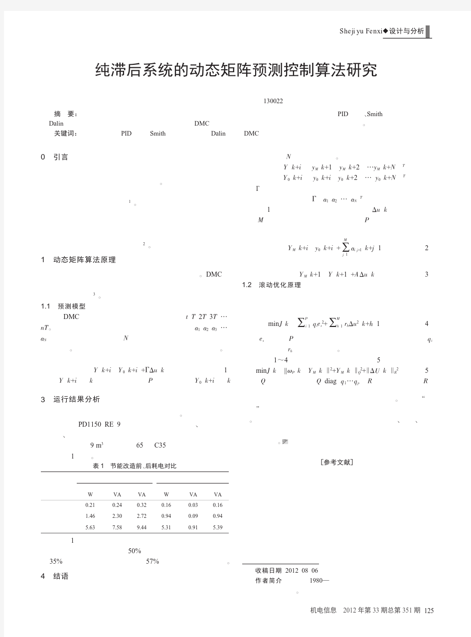
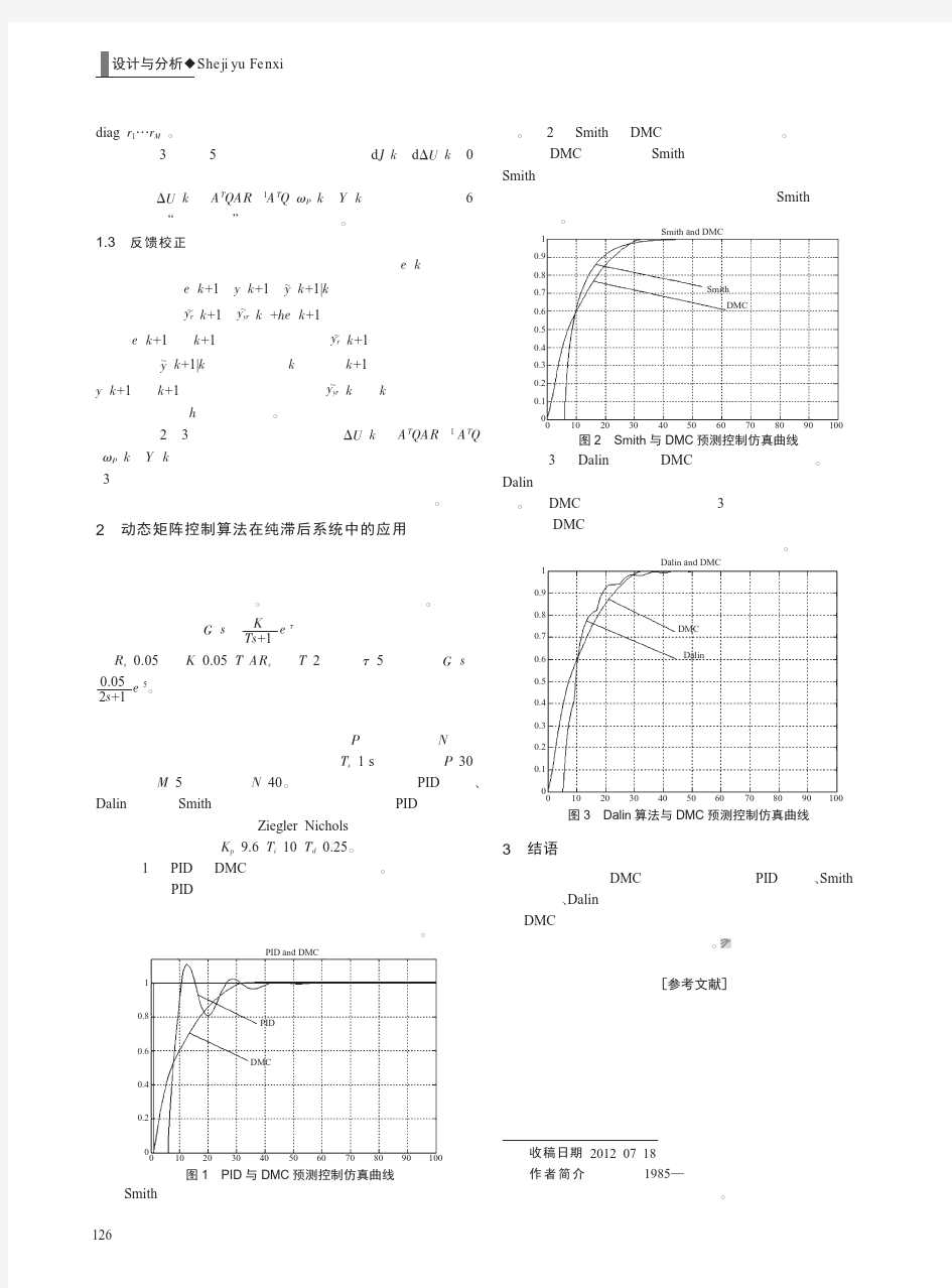
纯滞后系统的动态矩阵预测控制算法
一阶纯滞后系统的控制方法研究
题目一阶纯滞后系统的控制方法研究
摘要 在现代工业生产中,自动控制技术的使用越来越多,而随着工业和控制技术的发展,自动控制理论也在发展和完善,出现了多种控制方法如最基础的PID控制以及微分先行控制、中间微分控制、史密斯补偿控制、模糊控制、神经网络控制等。自动控制技术的发展在工业生产中遇到了一系列的问题:如在本文中所研究的一阶纯滞后系统的控制就是控制理论中一个较为重要的问题。由控制理论可知,无滞后控制系统(简单点说就是没有延迟)比有滞后系统更加稳定,更加容易控制。因此如何解决生产中滞后的问题在当前工业大生产中尤其重要。论文在常规PID控制也就是比例-积分-微分控制的基础上提出了三种控制方法即:微分先行控制、中间微分反馈控制、史密斯补偿控制。并对这三种方案进行Simulink仿真,检测其抗干扰性能。为便于分析,论文将所得仿真结果以图形的方式给予显示出来,形象生动便于理解。 关键词:自动控制,仿真,PID,复杂控制
The control method research of the first-order delay system Abstract The automatic control technology use more and more in modern industrial production, and as the industrial and control technology development, the automatic control theory are developed and perfected, a lot of controlled methods appear such as PID control which is the most basic control and differential first control, intermediate differential control, Smith compensation control, fuzzy control, nerve network control. Automatic control technology had experienced a series of questions in industrial production: as the first-order delay system control in this article which is a more important issue in the control theory. Known by the control theory,a no lag control system (simple say is no delay) is more stable and more easily controlled than a delay system . So it is particularly important of how to solve the lagging problem in the current industrial production . The articles propose three control methods such as differential first control 、the middle of differential feedback control、smith compensation control base the conventional PID control in the other word is proportional - integral - derivative controller .And simulate this three programs by the simulink, testing its interference fearure. For convenient analyze the simulation result , the paper of the study derive from the simulation results by the graphical ,which we can easy understand and clear know the mean in the article. Key Words:automatic control; simulation; PID; complicated control
大纯滞后过程特性Smith预估控制
过程控制系统课程设计题目之十三 大纯滞后过程特性Smith 预估控制 对于一个大纯滞后过程特性的对象:s PC e s s s G 10) 12)(3(1 )(-++= ,试设计一 个Smith 预估控制系统,并用SIMULINK 和MATLAB 程序仿真实现。当系统设定值R(s)为1时,调整PI 参数,使过渡过程尽可能满意。(假设检测变送环节的传递函数为1);比较在预估模型有偏差时,在相同的输入条件下,与预估模型无偏差情况的仿真结果;如果系统有扰动信号F(s)为单位阶跃信号或SINS 信号时,比较系统的仿真结果;如有可能,再试设计一种改进的Smith 预估器。 实验报告要求: 1、供系统仿真图; 2、按照题目要求,给出每个实验的仿真结果图; 3、根据以上仿真结果,分析)(s G PC 有滞后与无滞后情况下,PI 参数整定的特点。
大纯滞后过程特性Smith预估控制 摘要:Matlab 是一套高性能的数值计算和可视化软件。它集数值分析、矩阵计算、信号分析与图形显示为一体,构成的一个方便的、界面友好的用户环境。历经二十几年的发展和竞争,现已成为国际公认的最优秀的科技应用软件。Matlab 最突出的特点就是简洁、它用直观的、符合人们思维习惯的代码、代替C 语言和FORTRAN 语言的冗长代码。为此,Matlab 获得了对应用学科的极强适应力。在国内外高校、Matlab 已成为大学生,硕士生、博士生必须掌握的基本技能。在设计研究学位和工业部门,Matlab 已经成为研究和解决各种具体工程问题的一种标准软件。Matlab 软件广泛用于数字信号分析,系统识别,时序分析与建模,神经网络、动态仿真等方面有着广泛的应用。利用Matlab 这个最优秀的科技软件,把计算机技术与信号分析紧密地结合起来,对信号进行分析处理仿真研究,经实例验证,取得了非常好的效果,具有一定的实用价值。本文控制系统为研究主体,提出一种Smith 预估控制算法,通过设计自适应非线性反馈回路来自适应调节参数,从而满足对象参数大幅度变化的要求。 关键词:Matlab;纯滞后;Smith 预估控制器;Simulink Pure time-delay system control algorithm of Smith Abstract:Matlab is a software.of high performance of numerical calculation and visualization It get numerical analysis, calculation and signal analysis and graphic display together, constitute a convenient, interface, user friendly environment. After 20 years of development and competition, has become internationally recognized the best technology application software. The most prominent feature of Matlab is concise, it use the people's thinking and habits of the visual code, instead of C language and FORTRAN language lengthy code.So, Matlab acquire the subject of application for science. Matlab,has become acollege students’, masters’ or doctors’ basic skills which must be grasp of both at home and abroad ,. In the design research degree and industrial department, Matlab has become the research and solve specific engineering problems are a standard software. Matlab software widely used in digital signal analysis, system identification, timing analysis and modeling, neural network, dynamic simulation, etc in a wide range of applications. The best use of Matlab software technology, computer technology and signal analysis closely together, the signal analysis simulation, and achieved very good results since it has certain practical value. This control system as a main body of research, and put forward a II
动态矩阵和模型预测控制的半自动驾驶汽车(自动控制论文)
Dhaval Shroff1, Harsh Nangalia1, Akash Metawala1, Mayur Parulekar1, Viraj Padte1 Research and Innovation Center Dwarkadas J. Sanghvi College of Engineering Mumbai, India. dhaval92shroff@https://www.360docs.net/doc/9d16713282.html,; mvparulekar@https://www.360docs.net/doc/9d16713282.html, Abstract—Dynamic matrix and model predictive control in a car aims at vehicle localization in order to avoid collisions by providing computational control for driver assistance whichprevents car crashes by taking control of the car away from the driver on incidences of driver’s negligence or distraction. This paper provides ways in which the vehicle’s position with reference to the surrounding objects and the vehicle’s dynamic movement parameters are synchronized and stored in dynamic matrices with samples at regular instants and hence predict the behavior of the car’s surrounding to provide the drivers and the passengers with a driving experience that eliminates any reflex braking or steering reactions and tedious driving in traffic conditions or at junctions.It aims at taking corrective action based on the feedback available from the closed loop system which is recursively accessed by the central controller of the car and it controls the propulsion and steeringand provides a greater restoring force to move the vehicle to a safer region.Our work is towards the development of an application for the DSRC framework (Dedicated Short Range Communication for Inter-Vehicular Communication) by US Department of Traffic (DoT) and DARPA (Defense Advanced Research Projects Agency) and European Commission- funded Project SAVE-U (Sensors and System Architecture for Vulnerable road Users Protection) and is a step towards Intelligent Transportation Systems such as Autonomous Unmanned Ground and Aerial Vehicular systems. Keywords-Driver assist, Model predictive control, Multi-vehicle co-operation, Dynamic matrix control, Self-mapping I.INTRODUCTION Driver assist technologies aim at reducing the driver stress and fatigue, enhance his/her vigilance, and perception of the environment around the vehicle. It compensates for the driver’s ability to react [6].In this paper, we present experimental results obtained in the process of developing a consumer car based on the initiative of US DoT for the need for safe vehicular movement to reduce fatalities due to accidents [5]. We aim at developing computational assist for the car using the surrounding map data obtained by the LiDAR (Light Detection and Ranging) sensors which is evaluated and specific commands are issued to the vehicle’s propellers to avoid static and dynamic obstacles. This is also an initiative by the Volvo car company [1] where they plan to drive some of these control systems in their cars and trucks by 2020 and by General Motors, which aims to implement semi-autonomous control in cars for consumers by the end of this decade [18].Developments in wireless and mobile communication technologies are advancing methods for ex- changing driving information between vehicles and roadside infrastructures to improve driving safety and efficiency [3]. We attempt to implement multi-vehicle co-operative communication using the principle of swarm robotics, which will not only prevent collisions but also define specific patterns, which the nearby cars can form and pass through any patch of road without causing traffic jams. The position of the car and the position of the obstacles in its path, static or moving, will be updated in real time for every sampling point and stored in constantly updated matrices using the algorithm of dynamic matrix control. Comparing the sequence of previous outputs available with change in time and the inputs given to the car, we can predict its non-linear behavior with the help of model predictive control. One of the advantages of predictive control is that if the future evolution of the reference is known priori, the system can react before the change has effectively been made, thus avoiding the effects of delay in the process response [16]. We propose an approach in which human driving behavior is modeled as a hybrid automation, in which the mode is unknown and represents primitive driving dynamics such as braking and acceleration. On the basis of this hybrid model, the vehicles equipped with the cooperative active safety system estimate in real-time the current driving mode of non-communicating human-driven vehicles and exploit this information to establish least restrictive safe control actions [13].For each current mode uncertainty, a mode dependent dynamic matrix is constructed, which determines the set of all continuous states that lead to an unsafe configuration for the given mode uncertainty. Then a feedback is obtained for different uncertainties and corrective action is applied accordingly [7].This ITS (Intelligent Transport System) -equipped car engages in a sort of game-theoretic decision, in which it uses information from its onboard sensors as well as roadside and traffic-light sensors to try to predict what the other car will do, reacting accordingly to prevent a crash.When both cars are ITS-equipped, the “game” becomes a cooperative one, with both cars communicating their positions and working together to avoid a collision [19]. The focus is to improve the reaction time and the speed of communication along with more accurate vehicle localization. In this paper, we concentrate on improving vehicle localization using model predictive control and dynamic matrix control algorithm by sampling inputs of the car such as velocity, steering frame angle, self-created maps Dynamic Matrix and Model Predictive Control for a Semi-Auto Pilot Car
基于补偿控制大滞后过程控制系统研究
doi:10.3969/j.issn.1671-1041.2011.03.003 基于补偿控制大滞后过程控制系统研究 孟苹苹,谢文滔 (西南石油大学,成都610500) 摘要:在工业过程控制中,传统PID控制方式用于较复杂被控对象时,在超调量与稳定性等方面都难以获得令人满意的结果。本论文以内模控制器作为研究对象,完成了内模控制器中低通滤波器的设计与Matlab仿真研究,得到了不同情形下的频率特性曲线,同时,通过与传统PID控制对比,对不同类型控制方式的特点进行了分析研究,得到了有意义的研究结论,对实际工业过程控制具有一定实用参考价值。 关键词:内模控制;大滞后过程;Matlab仿真;PID控制 中图分类号:TP273文献标志码:A Research on process control system of large time delay based on compensation control MENG Ping-ping,XIE Wen-tao (Southwest Petroleum University,Chengdu610500,China) Abstract:In industrial process control,when PID control,a traditional control model was applied to some complicated controlled objects,usually control effect is not satisfied as good as expected.In this paper,by focusing study on internal model controller,design and Matlab simulation of the low-pass filter,a very important component in the internal model controller were completed.Amplitude and frequency characteristic curve were drawn under different cases.By compared with PID in controlling characteristics,meaningful conclusions were conducted which might be applicably valuable to in-dustrial process control in practice. Key words:internal model control;great lag process;Matlab simulation;PID control 0引言 过程控制技术近年来发展迅速,特别是在计算机,网络通信和先进控制理论的带动下,过程控制的检测,执行仪表及控制系统日益向智能化方向发展[1]。 在化工、炼油、冶金等一些复杂工业过程中,广泛存在着较大的纯滞后。纯滞后往往是由于物料或能量需要经过一个传输过程而形成的,这类时间滞后系统的控制是世界公认的控制难题。由于纯滞后的存在,使得被控量不能及时地反映系统所受的扰动,从而产生明显的超调,使得控制系统的稳定性变差,调节时间延长。 传统的过程控制系统中,主要运用传统的PID控制,Smith控制,对于被控对象简单的系统,可以得到预期的效果,但是遇到大滞后的被控对象,其控制效果难以达到预定的效果,对于滞后系统,其τ/T>0.5,在这种情况下,就需要提出一种先进的PID控制器,使其在大滞后环境下,也能得到预期的控制效果。在本文中采用直流无刷电机作为被控对象[2],通过仿真说明采用内模控制的电机系统控制精度高、响应快、稳定性和鲁棒性良好。 1内模控制技术[3-4] 1.1内模控制技术简介 内模控制是在模型没有误差,而且可得到这个假设条件下的理想反馈控制。内模控制系统的典型框图如图1所示。 图1内模控制结构图 在实际工作中,模型与实际过程总会存在误差。针对上述情况,设计内模控制器时可首先将过程模型作因式分解如下: G ^ p (s)=G ^ p+ G ^ p- (1) □研究报告□仪器仪表用户 8 EIC Vol.182011No.3欢迎光临本刊网站http://www.eic.com.cn
动态矩阵控制算法
MATLAB 环境下动态矩阵控制实验 一 算法实现 设某工业对象的传递函数为:G P (s)=e -80s /(60s+1),采用DMC 后的动态特性如图1所示。在仿真时采样周期T=20s ,优化时域P=10,控制时域M=2,建模时域N=20。 MATLAB 程序1: g=poly2tfd(1,[60 1],0,80);%通用传递函数模型转换为MPC 传递函数模型 delt=20; %采样周期 nt=1; %输出稳定性向量 tfinal=1000; %截断时间 model=tfd2step(tfinal,delt,nt,g);%传递函数模型转换为阶跃响应模型 plant=model; %进行模型预测控制器设计 p=10; %优化时域 m=2; %控制时域 ywt=[];uwt=1; %设置输入约束和参考轨迹等控制器参数 kmpc=mpccon(plant,ywt,uwt,m,p);%模型预测控制器增益矩阵计算 tend=1000;r=1; %仿真时间 [y,u,yrn]=mpcsim(plant,model,kmpc,tend,r);%模型预测控制仿真 t=0:20:1000; plot(t,y) xlabel('图1 DMC 控制系统的动态阶跃响应曲线(time/s)'); ylabel('响应曲线'); 0100 2003004005006007008009001000 0.2 0.4 0.6 0.8 1 1.2 1.4 图1 DMC 控制系统的动态阶跃响应曲线(time/s) 响应曲线 图中曲线为用DMC 控制后系统的阶跃响应曲线。从图中可以看出:采用DMC 控制后系统的调整时间小,响应的快速性好,而且系统的响应无超调。该结果是令人满意的。
大纯滞后在对象控制方法应用研究
大纯滞后在对象控制方法应用研究 摘要:针对一般工业过程中存在的大纯滞后问题,提出了一种克服大纯滞后的预测控制方法。利用递推最小二乘法进行参数估计,获得对象的一阶简化模型,提出了一种Smith预估神经元控制器设计方法,再用构建的神经网络预测模型预测出未来相应时刻的系统输出,然后用该输出来调整当前时刻的控制量,从而达到预期的控制目的,仿真结果验证了该方法的有效性。 关键词:神经网络;预测控制;大纯滞后 0 前言 一般工业过程中都具有非线性大纯滞后的特点,特别是滞后较大(即额定滞后S/T>0.5)的系统,常规控制往往无能为力。采用Smith控制是解决对象大纯滞后问题的有效方法,但它需要建立对象的精确的数学模型,而且鲁棒性和抗干扰能力较差,面向对象的神经元模型及其学习算法具有算法简单、适应性好等优点,但是对于大纯滞后过程,由于被控量的偏差不能及时反映控制量的变化影响了神经元的控制效果。 预测控制是上世纪70年代兴起的一种新控制算法,在工业上已被广泛应用,其主要思想是:在当前时刻,基于过程的动态模型预测未来一定时域内每个采样周期(或按一定间隔)的过程输出,即可以根据当前的输入预测未来多个时刻的输出,从而根据控制要求调整下一时刻的控制量,有利于对纯滞后系统的控制,将预测函数控制应用于大纯滞后温度控制系统,减少了稳态静差,但超调量偏大,要有一种具有自补偿功能的非线性预测反馈校正法,提高了系统的鲁棒性,但该方法限于纯滞后时间已知的情况下,对于纯滞后参数未知或者改变的情况未加讨论。 根据上述情况提出一种用神经网络辨识系统的滞后时间参数,用预测控制算法实现对大纯滞后对象的控制方法。其中预测模型是用神经网络逼近被控的动态对象而建立的,从而无需知道系统的精确数学模型。 1 神经元模型及控制系统 1.1神经元模型 针对将神经网络直观套用于自动控制中存在的局限性,提出了一种面向控制的神经元模型它的输出u(t)可以表示为
施工项目进度控制原理修订稿
施工项目进度控制原理 Document number【SA80SAB-SAA9SYT-SAATC-SA6UT-SA18】
施工项目进度控制原理 摘要:本文通过分析影响施工项目进度的五大因素,从而得出施工项目进度控制的六方面原理。施工项目进度控制与投资控制和质量控制一样,是项目施工申的重点控制之一。它是保证施工项目按期完成,合理安排资源供应、节约工程成本的重要措施。关键词:施工项目进度控制原理 一、施工项目进度控制概述 (一)施工项目进度控制的概念 施工项目进度控制与投资控制和质量控制一样,是项目施工申的重点控制之一。它是保证施工项目按期完成,合理安排资源供应、节约工程成本的重要措施。 施工项目进度控制是指在既定的工期内,编制出最优的施工进度计划,在执行该计划的施工中,经常检查施工实际进度情况,并将其与计划进度相比较,若出现偏差,便分析产生的原因和对工期的影响程度,找出必要的调整措施,修改原计划,不断地如此循环,直至工程竣工验收。施工项目进度控制的总目标是确保施工项目的既定目标工期的实现,或者在保证施工质量和不因此而增加施工实际成本的条件下,适当缩短施工工期。 (二)施工项目进度控制方法、措施和主要任务
1.施工项目进度控制方法 施工项目进度控制方法主要是规划、控制和协调。规划是指确定施工项目总进度控制目标和分进度控制目标,并编制其进度计划。控制是指在施工项目实施的全过程中,进行施工实际进度与施工计划进度的比较,出现偏差及时采取措施调整。协调是指协调与施工进度有关的单位、部门和工作队组之间的进度关系。 2.施工项目进度控制的措施 工项目进度控制采取的主要措施有组织措施、技术措施、合同措施·经济措施和信息管理措施等。 组织措施主要是指落实各层次的进度控制的人员,具体任务和工作员任;建立进度控制的组织系统;按着施工项目的结构、进展的阶段或合同结构等进行项目分解,确定其进度目标,建立控制目标体系;确定进度控制工作制度,如检查时间、方法、协调会议时间、参加人等;对影响进度的因素分析和预测。技术措施主要是采取加快施工进度的技术方法。合同措施是指对分包单位签定施工合同的合同工期与有关进度计划目标相协调。经济措施是指实现进度计划的资金保证措施。信息管理措施是指不断地收集施工实际进度的有关资料进行整理统计与计划进度比较,定期地向建设单位提供比较报告。 3.施工项目进度控制的任务 施工项目进度控制的主要任务是编制施工总进度计划并控制其执行,按期完成整个施工项目的任务;编制单位工程施工进度计划并控制其执行,按期完成单位工程的施工任务;编制分部分项工程施工进
预测控制MATLAB仿真与设计
动态矩阵控制算法实验报告 院系:电子信学院 姓名:郝光杰 学号:172030039 专业:控制理论与控制工程 导师:俞孟蕻
MATLAB环境下动态矩阵控制实验 一、实验目的: 对于带有纯滞后、大惯性的研究对象,通过动态控制矩阵的MATLAB的直接处理与仿真实验,具有较强的鲁棒性和良好的跟踪性。输入已知的控制模型,通过对参数的选择,来取的良好的控制效果。 二、实验原理: 动态矩阵控制算法是一种基于被控对象非参数数学模型的控制算法,它是一种基于被控对象阶跃响应的预测控制算法,以对象的阶跃响应离散系统为模型,避免了系统的辨识,采用多步预估技术,解决时延问题,并按照预估输出与给定值偏差最小的二次性能指标实施控制,它适用于渐进稳定的线性对象,系统动态特性中存在非最小相位特性或纯滞后都不影响算法的直接使用。 三、实验环境: 计算机 MATLAB2016b 四、实验步骤: 影响控制效果的主要参数有: 1)采样周期T与模型长度N 在DMC中采样周期T与模型长度N的选择需要满足香农定理和被控对象的类型及其动态特性的要求,通常需要NT后的阶跃响应输出值接近稳定值。 2)预测时域长度P P对系统的快速性和稳定性具有重要影响。为使滚动优化有意义,应使P 包含对象的主要动态部分,P越小,快速性提高,稳定性变差;反之,P越大,系统实时性降低,系统响应过于缓慢。 3)控制时域长度M
M控制未来控制量的改变数目,及优化变量的个数,在P确定的情况下,M越小,越难保证输出在各采样点紧密跟踪期望输出值,系统响应速度缓慢, 可获得较好的鲁棒性,M越大,控制机动性越强,改善系统的动态性能,但是稳定性会变差。 五、实例仿真 (一)算法实现 设GP(s)=e-80s/(60s+1),采用DMC后的动态特性如图1所示,采样周期 T=20s,优化时域P=10,M=2,建模时域N=20。 MATLAB程序1: g=poly2tfd(1,[60 1],0,80);%通用传函转换为MPC模型 delt=20; %采样周期 nt=1; %输出稳定性向量 tfinal=1000; %截断时间 model=tfd2step(tfinal,delt,nt,g);%传函转换为阶跃响应模型 plant=model;%进行模型预测控制器设计 p=10; m=2; ywt=[];uwt=1;%设置输入约束和参考轨迹等控制器参数 kmpc=mpccon(plant,ywt,uwt,m,p);%模型预测控制器增益矩阵计算 tend=1000;r=1;%仿真时间 [y,u,yrn]=mpcsim(plant,model,kmpc,tend,r);%模型预测控制仿真 t=0:20:1000;%定义自变量t的取值数组 plot(t,y) xlabel(‘图一DMC控制动态响应曲线(time/s)’); ylabel(‘响应曲线’); 结果如下: Percent error in the last step response coefficient
预测控制中动态矩阵控制DMC算法研究及仿真
安徽大学 本科毕业论文(设计) (内封面) 题目:预测控制中动态矩阵控制DMC算法研究 学生姓名:张汪兵学号:P4*******院(系):电子科学与技术学院专业:自动化 入学时间:2006年9月导师姓名:张倩职称/学位:硕士 导师所在单位:安徽大学电子科学与技术学院
预测控制中动态矩阵控制DMC算法研究及仿真 摘要:动态矩阵控制(dynamic matrix control, DMC)算法是一种基于对象阶跃响应预测模型、滚动实施并结合反馈校正的优化控制算法,是预测控制算法之一。本文阐述了预测控制的产生、发展及应用,进一步介绍动态矩阵控制算法的产生和现状,就当前动态矩阵控制算法在实际工业控制领域中发展应用现状以及今后可能的研究发展方向作了分析。并对动态矩阵控制的算法作了推导,在理论依据方面给予证明。可是在实际工业控制领域中,大多数被控对象都是多变量的,本文通过对该算法作了有约束、多变量两方面的改进,使该算法实际应用性更强。文章还对该算法进行了 matlab 仿真,并对仿真结果进行分析研究,予以验证。 关键词:预测,动态矩阵控制,模型,反馈矫正,有约束,多变量。 Forecast for control of Dynamic Matrix Control DMC algorithm Abstract Dynamic Matrix Control (dynamic matrix control, DMC) algorithm is a step response based on the object prediction model, and rolling implementation and optimization of the feedback correction control algorithm, is one of predictive control algorithms. This paper describes the control forecast the rise, development and application of further information on Dynamic Matrix Control algorithm and the formation of the status quo on the current dynamic matrix control algorithm in the actual control in the field of industrial development and possible future application of the research and development direction of an analysis. Dynamic Matrix Control and the algorithm is derived, in terms of the theoretical basis for that. But in practice in the field of industrial control, the majority of objects are charged with multiple variables, the paper through the binding of the algorithm, two more variables in the promotion and improvement of the algorithm so that a more practical application. The article also has the algorithm matlab simulation, and analysis of simulation results to be verified. Key words: forecasting; dynamic matrix control; model; feedback correction; binding; multivariable
动态矩阵
MATLAB环境下动态矩阵控制实验 姓名:刘慧婷 学号:132030052 专业:控制理论与控制工程 课程:预测控制 指导老师:曾庆军
一算法实现 设某工业对象的传递函数为:G P(s)=e-80s/(60s+1),采用DMC后的动态特性如图1 所示。在仿真时采样周期T=20s,优化时域P=10,控制时域M=2,建模时域N=20。 MATLAB程序1: 仿真结果如下图所示: 图中曲线为用DMC控制后系统的阶跃响应曲线。从图中可以看出:采用DMC控 后系统的调整时间小,响应的快速性好,而且系统的响应无超调。该结果是令人满意的。
二P和M对系统动态性能的影响 1.P对系统性能的影响 优化时域P表示我们对k时刻起未来多少步的输出逼近期望值感兴趣。当采样期T=20s,控制时域M=2,建模时域N=20,优化时域P分别为6,10和20时的阶跃响应曲线 MATLAB程序2: 仿真结果如下图所示:
图中曲线1为P=6时的阶跃响应曲线;曲线2为P=10时的阶跃响应曲线;曲线 为P=20时的阶跃响应曲线。从图中可以看出:增大P,系统的快速性变差,系统的稳定性增强;减小P,系统的快速性变好,稳定性变差。所以P的选择应该兼顾快速性和稳定性。 2.M对系统性能的影响 控制时域M表示所要确定的未来控制量的改变数目。当采样周期T=20s,优化时域P=20,建模时域N=20,控制时域M分别取4,2和1时系统的响应曲线如图3所示。MATLAB程序3:
图中曲线1为M=4时的响应曲线;曲线2为M=2时的响应曲线;曲线3为M=1 时的响应曲线。从图中可以看出:减小M,系统的快速性变差,系统的稳定性增强;增大M,系统的快速性变好,稳定性变差。增大P和减小M效果类似,所以在选择时,可以先确定M再调整P,并且M小于等于P。 三模型失配时的响应曲线 当预测模型失配时,即当G M(S)≠G P(S),当G M(S)=2e-50s/(40s+1)时的响应曲线如图4所示。 MATLAB程序4: