工业尾气变压吸附提纯一氧化碳中试(英文)
Chinese Journal of Chemical Engineering, 16(5) 715—721 (2008)
Pilot-scale Experiment for Purification of CO from Industrial Tail Gases by Pressure Swing Adsorption*
CHEN Yubao (陈玉保)1,2, NING Ping (宁平)2,**, XIE Youchang (谢有畅)3, CHEN Yunhua (陈云华)2, SUN Hao (孙暠)2 and LIU Zhiyun (刘志云)4
1 Department of Energy and Environmental Science, Yunnan Normal University, Kunming 650092, China
2 Department of Environmental Science and Engineering, Kunming University of Science and Technology, Kun-
ming 650093, China
3 Department of Chemistry and Molecular Engineering, Peking University, Beijing 100871, China
4 Yunnan Jiehua Chemistry Group Co., Ltd, Kaiyuan 661600, China
Abstract Using pressure swing adsorption (PSA) technology to purify carbon monoxide (CO) discharged from industrial gases is a high-efficiency and economical method. In this article, a four-bed PSA experiment for CO puri-fication was improved and optimized, in which a set of 120 m3·h-1 pilot-scale PSA device was developed to purify CO from industrial tail gases, a set of control systems suitable for industry production was developed, and the in-fluences of the operating parameters on CO purification were investigated. The experimental results indicated that the pilot-scale PSA device could produce qualified product gas and get high CO recovery ratio under optimized conditions. The research may provide reliable fundamental data, for industrial scale utilization of CO, from indus-trial tail gases, and have strong market competitive power and a broad promoted application prospect.
Keywords pressure swing adsorption, purification, separation, carbon monoxide
1 INTRODUCTION
The demand for energy and synthetic materials is increasing gradually in the modern economic world. Petroleum, coal, and natural gas, which are flammable mineral resources, occupy 85% of the world’s energy and organic synthesis industry [1]. However, all of these industrial tail gases include green-house gases [2], in which CO2 contributes 55% to the green-house effect [3], which brings about global climate change, one of the greatest environmental problems of modern society [4].
With the shortage in energy and chemical materi-als, especially the increasing consumption of petro-leum resources, C1 chemical industry, which primarily includes coal and natural gas, is significantly impor-tant. In 2006, the output of organic products produced by CO was close to 20 thousand million RMB in China and was over one hundred billion RMB in the world. The demand for carbonyl synthetic products and the element material CO are increasing gradually [5]. High-purity CO is a very important production mate-rial in the C1 chemical industry. However, many in-dustrial processes discharge CO in tail gases [6, 7], and most of them are used as fuel because that CO con-centration is too low to retrieve as the recovery of CO is expensive [8, 9]. If CO in tail gases can be purified and used in the C1 chemical industry, it will not only achieve great economic benefit because of the lower production costs [10], but there will also be an envi-ronmental benefit, as there will be less discharge of greenhouse gases, CO and CO2. For using CO from industrial tail gases effectively, high-efficiency CO pu-rification technology needs to be developed and applied.
In this study, CO, purified by the method of PSA has higher purity, higher recovery ratio, and lower cost and energy consumption. Compared with the other methods of PSA to purify CO [11-14], the characters of the optimized four-bed PSA process for CO purifica-tion are as follows: (1) the pressure process is divided into direct and indirect pressure equalization, (2) the purge step is canceled in PSA circulation, resulting in high productivity and high CO recovery ratio, (3) the final pressurization step is canceled, which promotes productivity again.
2 EXPERIMENTAL
2.1 Experimental devices and operational procedure
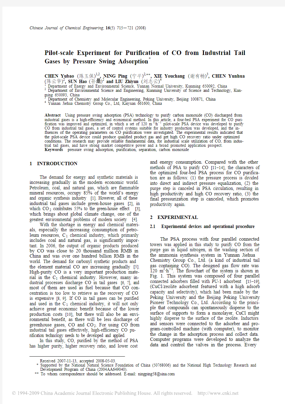
The PSA process with four parallel connected towers was applied in this study to purify CO from the purge gas in liquid nitrogen, in the washing section of the ammonia synthesis system in Yunnan Jiehua Chemistry Group Co., Ltd. (a kind of industrial tail gas containing CO). The designed gas flow rate was 120 m3·h-1. The flowchart of the system is shown in Fig. 1. This system was composed of four parallel connected adsorbers filled with PU-1 adsorbent [15-19], (CuCl/zeolite adsorbent featured with a high adsorb capacity and selectivity), which had been made by the Peking University and the Beijing Peking University Pioneer Technology Co., Ltd. According to the princi-ple that compounds can spontaneously disperse to the surface of supports to form a monolayer, CuCl might highly disperse to the surface of the zeolite. Inductors and sensors were connected to the adsorber and pro-gram-controlled machine (with computer), to monitor the change in the adsorption process and collect data. Computer programs were developed to analyze the data and control the valves in the process. Every
Received 2007-11-13, accepted 2008-05-03.
* Supported by the National Natural Science Foundation of China (50768006) and the National High Technology Research and Development Program of China (2004AA649040).
** To whom correspondence should be addressed. E-mail: ningping58@https://www.360docs.net/doc/f215961054.html,
Chin. J. Chem. Eng., Vol. 16, No. 5, October 2008
716 adsorber had one pressure sensor and three K-type thermocouples. CO concentration in feed gas, waste gas, and product gas were analyzed by QGS-08D online CO analyzer, and the ingredients of the product gas were analyzed by a SC3000 chromatography workstation. Additionally, the pilot-scale device was equipped with one water circulation vacuum pump (WCVP) to regenerate the desiccant and two WCVPs to regenerate the adsorbent. Besides four adsorbers (A to D), there were seven pressure equalization buffers (PEBs) to equalize the pressure in the adsorber be-tween the adsorption and regeneration steps, under dif-ferent pressures. The system was also equipped with some devices, including feed gas buffer, product gas buffer, ZW-1.5/7 product gas compressor, and so on.
The equipment of the pilot-scale experiment is shown in Table 1. Main parameters of the stuff filled
in the pilot-scale device are shown in Table 2. The
Figure 1 Flowchart of pilot-scale device for four-bed PSA process
TA/B/C/D —A/B/C/D adsorber; TE -K —PEB; V1—feed gas buffer; V2A/B —tank next to vacuum pump; V2C —CO container; V3—rinse gas buffer; V4—product gas buffer; V5—final buffer; V6—water segregator; P1A/B —product gas vacuum pump; P2—desiccant vacuum pump; C1—product gas compressor; T2A/B —drying tower; T3A/B —deoxidizing
tower;
needle P pressure meter or pressure sensor ; T thermal couple;F
mass flow meter; A
sample or online gas analytical apparatus
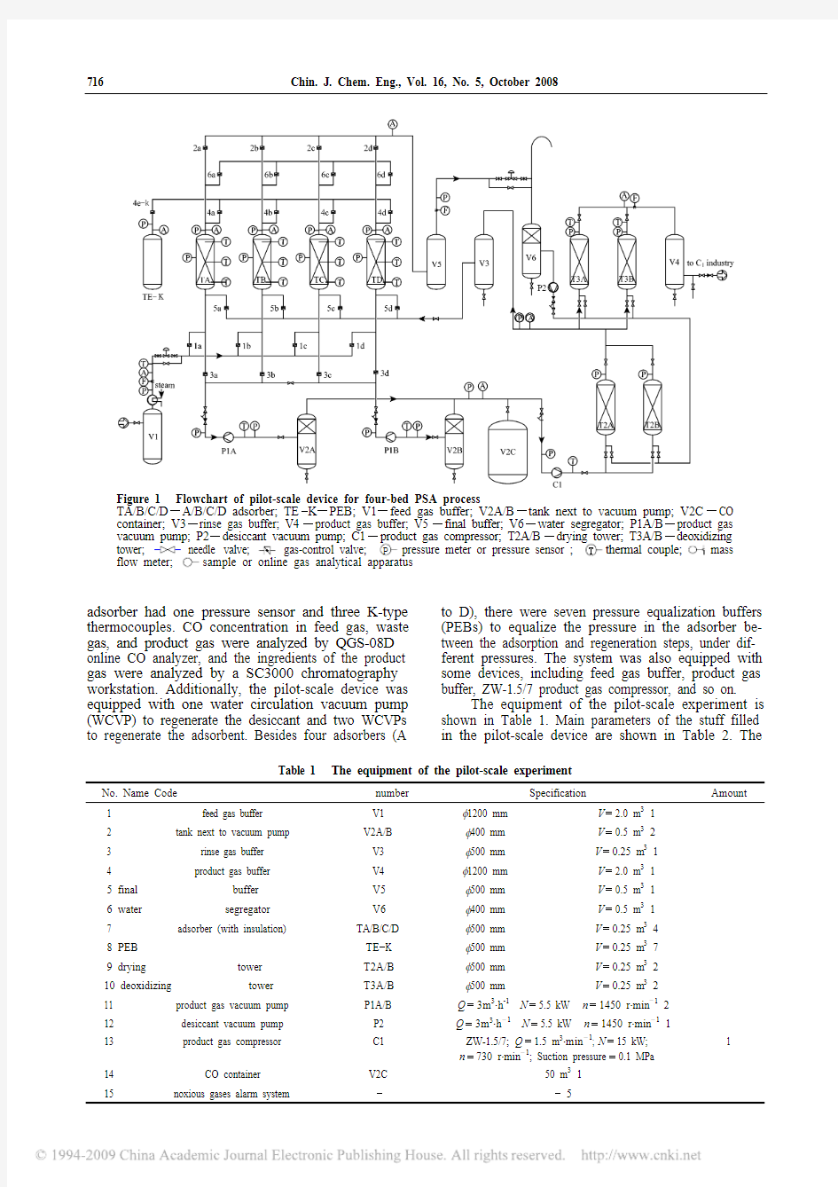
Table 1 The equipment of the pilot-scale experiment
No. Name Code number Specification
Amount
1 feed gas buffer V1 φ1200 mm V =2.0 m 3 1
2 tank next to vacuum pump
V2A/B φ400 mm V =0.5 m 3 2 3 rinse gas buffer V3 φ500 mm V =0.25 m 3 1 4
product gas buffer
V4
φ1200 mm
V =2.0 m 3 1 5 final buffer V5 φ500 mm V =0.5 m 3 1 6 water segregator V6
φ400 mm V =0.5 m 3 1 7
adsorber (with insulation)
TA/B/C/D
φ500 mm V =0.25 m 3 4 8 PEB TE -K
φ500 mm
V =0.25 m 3 7 9 drying tower T2A/B φ500 mm V =0.25 m 3 2 10 deoxidizing tower T3A/B
φ500 mm V =0.25 m 3 2
11 product gas vacuum pump P1A/B Q =3m 3·h -1 N =5.5 kW n =1450 r·min -1 2 12 desiccant vacuum pump P2 Q =3m 3·h -
1 N =5.5 kW n =1450 r·min -
1 1 13 product gas compressor
C1 ZW-1.5/7; Q =1.5 m 3·min -
1; N =15 kW;
n =730 r·min -
1; Suction pressure =0.1 MPa
1
14 CO container V2C 50 m 3 1
15
noxious gases alarm system
-
- 5
Chin. J. Chem. Eng., Vol. 16, No. 5, October 2008
717
optimized four-bed PSA process and parameters are shown in Table 3 and Table 4 respectively.
During the process, twelve steps occurred in every adsorber. An adsorber TA was taken as an ex-ample below. (1) AD: After being pressurized by a gas compressor, the feed gas went through buffer V1 and flowed into TA, in which CO was selectively adsorbed and other ingredients were released. (2) DD1: The gas-control valve in the TA entrance was closed and TA was connected to TC, which had completed the IR2 process, and then the first depressurization oc-curred. (3) ID2: TA was connected to the first PEB, and the second depressurization happened in TA. (4) ID3: TA was connected to the second PEB, and the third depressurization happened in TA. (5) ID4: TA was connected to the third PEB, and the fourth de-pressurization happened in TA. (6) DD5: TA was connected to TB, which had completed the EV process and depressurization for the last time was fulfilled. (7) EV: TA was connected to P1A and then vacuumized. CO adsorbed by PU-1adsorbent was desorbed and flowed into V2A. If the product gas CO was up to standard, it would be sent into T3A and V4 and used for C 1 chemical industry. Else it would be sent into V3 and the adsorber. (8) DR5: TA was connected to TB, which had completed the ID4 process and had begun the first repressurization. The sequence was counted in inverted order to match the sequence of depressuriza-tion. (9) IR4: TA was connected to the third PEB and began the second repressurization. (10) IR3: TA was
connected to the second PEB and began the third rep-ressurization. (11) IR2: TA was connected to the first PEB and began the fourth repressurization. (12) DR1: TA was connected to TD, which had finished the AD process and had begun the last repressurization of TA. Then TA went to the next circulation.
According to the results over a long run, the in-gredients of the purge gas in the liquid nitrogen wash-ing section of ammonia synthesis system are shown in Table 5.
Table 5 Ingredient analysis of the purge gas from liquid nitrogen washing section in ammonia synthesis system
Ingredient V olume fraction/%
CO 25-45 N 2 41-64 CH 4 9.3-17.8 H 2
2.5-8
2.2 Processing method for experimental data 2.2.1 Dynamic equilibrium adsorption quantity
The dynamic equilibrium adsorption quantity can be measured by Dynamic Column Breakthrough Test (DCBT) [20]. The dynamic equilibrium adsorption quantity formula, under certain adsorption pressure and temperature, is shown in Eq. (1).
Table 2 Main parameters of the stuff filled in the pilot-scale device
Parts Tower volume/m 3 Filled stuff Mass of filled stuff per tower/kg
Density of filled stuff×10-
3/kg·m -
3 Bed voidage
adsorber TA/B/C/D 0.25 PU-1 adsorbent 226±1 0.904 0.33 drying tower 0.25 activated alumina 184 0.736 - deoxidizing tower
0.25
deoxidizer
172
0.688
-
Table 3 The optimized four-bed PSA process for CO purification
Step 1 2 3 4 5
6 7
89 10 11 12 13(1)TA AD DD ID ID ID PG DD EV DR IR IR IR DR (AD) 1 2 3 4 5 5 4 3 2 1
TB
EV DR IR IR IR DR AD
DD ID ID ID PG DD (EV) 5 4 3 211
2
3
4
5 TC EV DR IR IR IR DR AD DD ID ID ID PG DD (EV)
5
4
3 2
1 1
2
3
4
5
TD PG DD
EV
DR IR IR IR DR AD DD ID ID ID
5
5
4
3
2
1
1 2
3
4
Note: (1) AD —adsorption; DD —direct depressurization; ID —indirect depressurization; PG —purge; EV —evacuation; DR —direct
repressurization; IR —indirect repressurization.
(2) Purge process and system connection should be kept, whereas, the purge process needs to be removed when the system is running.(3) The values in the table are the indirect average pressure (n =3) as a result of the study.
Table 4 Experimental conditions of a PSA cyclic process
Time/s Adsorption pressure /kPa Desorption pressure /kPa Feed gas flow rate /m 3·h -
1 CO concentration in feed gas/% Temperature of feed gas /K DR5IR4IR3IR2DR1AD DD1ID
2 ID
3 ID
4 DD
5 EV
The total cycle time
/s 300 20 120 38.71-41.45 304 1616161616100161616 16 16 228488
Chin. J. Chem. Eng., Vol. 16, No. 5, October 2008
718 ()in end d *0273.15101.325
22400i
i P
V V V C T q m
?×
?××=
× (1)
2.2.2 Product gas recovery ratio
The product gas recovery ratio represents the de-gree of recovery of active ingredients in feed gas and is an important index to measure the efficiency of the PSA device. It indicates the consumption of the active ingredient, and can be calculated by the ratio of abso-lute quantity of the active ingredient in product gas and feed gas. The formula is shown in Eq. (2).
P P F F V X V X η×=× (2)
3 RESULTS AND DISCUSSION 3.1 Breakthrough curve
Breakthrough curve is an important characteristic curve in the PSA process. It reflects adsorption equilib-rium relations, adsorption kinetics, and mass-transfer mechanism in the mobile phase and fixed phase and is also the main basis of engineering design and opera-tion [21]. Breakthrough curves of the four adsorption beds are shown in Fig. 2. It was obtained under the conditions where the adsorption temperature was 318 K, adsorption pressure was 300 kPa, CO concentration in the feed gas varied from 37.8% to 40% and the feed
gas flow rates were 120 m 3·h -1 (TA), 118 m 3·h -
1 (TB),
119 m 3·h -1 (TC), and 118 m 3·h -
1 (TD), respectively. Influences of adsorption pressure on breakthrough curves of the adsorption bed were shown in Fig. 3, under the condition that CO concentration in the feed gas was about 40%. PU-1 adsorbent was first regener-ated by the product gas vacuum pump. To prevent air going into the adsorber, the opening of the discharging gas-control valve was delayed by 10 s. As shown in Fig. 2, there were some differences in the break-through curves because of the differences in the ad-sorbent filled in the adsorber, filling ways, tempera-ture, flow rate of feed gas, CO concentration, and so on. However there were no big differences in the breakthrough time of the four adsorption beds, which was around 130 s. At the beginning, there was a higher point of CO concentration in the waste gas. And then the breakthrough curve proceeded steadily. It could be explained that the adsorbent could not be desorbed completely and a certain amount remained
behind. When the next circulation began, part of these remains would be desorbed with the flushing action of the feed gas, under the condition that CO partial pres-sure was lower than CO balanced partial pressure, which led to high instant CO concentration in waste gas. Although, in the normal adsorption process (130 s), CO concentration in waste gas increased from 2% to 4%.
From Fig. 3, it can be seen that there were no big differences in breakthrough time of the same adsorp-tion bed under different pressures, which indicated that the influences of adsorption pressure on break-
through curves of the adsorption bed were acceptable.
Figure 3 Influences of adsorption pressure on breakthrough curves of adsorption bed ■ P =250 kPa, Q =112 m 3·h -
1; ▲ P =300 kPa, Q =119 m 3·h -1
;
▼ P =350 kPa, Q =120 m 3·h -1
3.2 Influences of feed gas flow rate on relative CO adsorption quantity
It can be seen from Fig. 4 that there were some differences in adsorption time under different feed gas flow rate. The adsorption time was 200 s and the rela-tive adsorption quantity of PU-1 adsorbent was 0.35
mol·kg -
1 when adsorption pressure was 300 kPa, feed
gas flow rate was 78 m 3·h -
1 and CO concentration in feed gas was 40.5%. Although, the adsorption time was 135 s and the relative adsorption quantity of PU-1
adsorbent was 0.33 mol·kg -
1 when the adsorption pressure was 300 kPa, the feed gas flow rate was 119
m 3·h -
1 and CO concentration in feed gas was 37.2%. Therefore, it showed that the relative adsorption quan-tity of PU-1 adsorbent declined with the increase in feed gas flow rate. It could be explained that with the increase in feed gas flow rate, gas residence time (GRT) decreased and the breakthrough point occurred in advance, though generally relative adsorption quan-
tity was in positive correlation with GRT.
Figure 4 Influence of feed gas flow rate on experimental result
▲ P =300 kPa, Q =78 m 3·h -1; ▼ P =300 kPa, Q =119 m 3·h -
1
Figure 2 Breakthrough curve of the four adsorption beds ■ TA; ● TB; ▲ TC; ▼ TD
Chin. J. Chem. Eng., Vol. 16, No. 5, October 2008 719
3.3 Influence of CO concentration in feed gas on product gas purity
Usually, CO concentration in feed gas varies with time because of the discontinuous operation of the ammonia synthesis system. Actually CO concentration in feed gas varies from 25% to 45%. The influence of the fluctuation on product gas purity is shown in Fig. 5. It can be seen that the influence of CO fluctuation on product gas purity is slight, because when CO con-centration in feed gas is low (25%), the product gas purity is still high. It can be explained by the mass transfer zone (MTZ) in the adsorber, which reaches the controlling station when the adsorption step is complete and results in little quantities of other ingre-dients getting into the product gas. However, when the CO concentration in the feed gas is higher (45%), be-cause of the control of the MTZ station, the increasing quantity of CO in waste gas is less and a large quan-tity of it is saved in the adsorber and PEB, which is adsorbed by the next circulation. CO concentration in product gas can be kept at more than 98%, with fluc-tuation, over a long run. According to the actual de-mand of CO concentration in product gas, higher pu-rity product gas can be obtained by the purge process
with lower CO recovery ratio.
Figure 5 Influence of CO concentration in feed gas on product gas purity ● product gas purity; ○ CO concentration in feed gas
3.4 Stability analysis of experimental operation
The purification influence of feed gas on the pilot-
scale device is shown in Fig. 6. As presented in Fig. 6, in any period of 20 cycles, when the adsorption pres-sure was constant at 300 kPa, the CO concentration
was 25%-45%, and flow rate was 115-123 m 3·h -
1. The CO concentration of product gas fluctuated from 97.98% to 99.74%, and correspondingly CO recovery efficiency fluctuated from 89.1% to 91.3%. This indi-cated that CO purification of the purge gas from the ammonia synthesis system had higher stability by PSA. This high stability was because of the efficiency of the pilot-scale facility and the optimization of the operation procedure.
3.5 T emperature variation of adsorption bed dur-ing a PSA cyclic process
It is well known that there was an exothermic phenomenon in the adsorption process and an endo-thermic phenomenon in the desorption process. There-fore the fluctuation of temperature in the adsorption bed was unavoidable, which was disadvantageous to CO purification. It was indicated in many studies [22] that the best separation condition was isothermal, in the adsorption bed. Consequently, it was necessary to study the influences of the thermal effect on the ad-sorption bed temperature during the adsorption and desorption process. Temperature variation of the ad-sorption bed during a PSA cyclic process is shown in Fig. 7, under the conditions that are shown in Table 4.
It showed that the temperature of the adsorption bed
Figure 6 Influences of cycle times on product gas purity and CO recovery ratio ■ product gas purity; ● CO recovery ratio
Figure 7 Temperature variation of adsorption bed during a PSA cyclic process ■ lower part of tower; ● middle part of tower; ▲ upper part of tower
Chin. J. Chem. Eng., Vol. 16, No. 5, October 2008 720
was less increased in the repressurization process as MTZ had not yet reached the temperature measure-ment point of the lower part of the adsorption bed. However, in the adsorption process, the temperature of the adsorption bed increased gradually from the lower part to the upper part with MTZ moving forward, adding up to 6.5 K, and the adsorption bed had al-ready reached the breakthrough point, whereas, the upper-part temperature kept on rising. With decreasing of pressure in the depressurization process, the tem-perature of the lower part and middle part of the ad-sorption bed fell a bit, whereas, the upper-part tem-perature continued to increase. Moreover, the tem-perature decreased in the evacuation process, which indicated that there was an endothermic phenomenon in the desorption process. The temperature decreased rapidly in the beginning 80 s of the evacuation process, which showed that the desorption quantity was large, and later gradually became constant when the desorp-tion time was prolonged.
4 CONCLUSIONS
(1) There was no big difference in breakthrough time in the four adsorption beds, which was around 130 s, and CO concentration in waste gas was kept within 4% when adsorption temperature was 318 K, adsorption pressure was 300 kPa, feed gas flow rate was 120 m3·h-1, and CO concentration in feed gas was kept at 40%. Fur-thermore, there was no big difference in breakthrough time of the same adsorption bed under different pressure.
(2) Product gas purity was higher than 98% and CO recovery ratio was about 90% under normal op-erations, which indicated that CO purification by PSA was very stable.
(3) The temperature of adsorption bed was less increased in the repressurization process. As in the adsorption process, the temperature of the adsorption bed increased gradually from the lower part to the upper part, and the adsorption bed had already reached the breakthrough point, whereas, the upper-part tem-perature kept on rising. In the depressurization process, the temperature of the adsorption bed’s lower part and middle part fell a bit, whereas, the upper-part tem-perature continued to increase. The temperature de-creased in the evacuation process, rapidly in the be-ginning 80 s, which showed that the desorption quan-tity was large, and then gradually became constant as the desorption time was prolonged.
(4) The relative adsorption quantity of PU-1 ad-sorbent reduced with an increase in the feed gas flow rate, which was 0.33 mol·kg-1 under normal operations.
The conclusions are reliable fundamental data for industrial design, on the condition that adsorption temperature is 318 K, adsorption pressure is 300 kPa, and breakthrough time is 130 s, the relative adsorption quantity of the adsorbent is about 0.33 mol·kg-1, product gas purity is higher than 98% and CO recov-ery ratio is about 90%.
ACKNOWLEDGEMENTS
The authors are grateful to YANG Hao for his cooperation in the experiment. NOMENCLATURE
C i volume percent of adsorption ingredients, %
m filled mass of adsorbent in adsorber, kg
P total pressure in adsorber (absolute pressure), kPa
*
i
q equilibrium adsorption quantity of ingredient i under partial pres-sure P i, mol·kg-1
T0initial adsorption temperature, K
V d dead space of adsorption bed, may be directly measured by the emptying method, ml
V end volume of adsorption ingredient in waste gas, be integral calcu-lated by breakthrough curve, ml
V F volume of feed gas, m3 (normal conditions)
V in volume of adsorption ingredient in gas intake, ml
V P volume of product gas, m3 (normal conditions)
X F the required ingredient concentration in feed gas, %
X P the required ingredient concentration in product gas, %
ηproduct gas recovery ratio
REFERENCES
1 Cai, Q.R., Peng, S.Y., Catalysis in C1 Chemistry, Chemical Industry
Press, Beijing (1995).
2 Song, C.S., “Global challenges and strategies for control, conversion
and utilization of CO2 for sustainable development involving energy,
catalysis, adsorption and chemical processing”, Catalysis Today, 115
(1-4), 2-32 (2006).
3 Chou, C.T., Chen, C.Y., “Carbon dioxide recovery by vacuum swing
adsorption”, Separation and Purification Technology, 39 (1/2), 51-65 (2004).
4 Yan, Z.Y., Zhang, H., Chen, C.H., Zeng, X.Z., “Global warming as a
result of CO2 emission and basic technical countermeasures”, Ad-
vances in Environmental Science, 7 (6), 175-181 (1999).
5 Geng, C.X., “Technology of pressure swing adsorption separating
CO and its application in industry of carbonyl synthesis”, Shanxi
Chemical Industry, 26 (3), 49-51 (2006). (in Chinese)
6 Lee, H., Choi, J.H., Yeo, Y.K., “Effect of evacuation and rinse condi-
tions on performance in PSA process for CO2 recovery”, Hwahak
Konghak, 38 (6), 809-816 (2000).
7 Li, Z.L., “Carbon monoxide purification and chemical industry ap-
plication (I)”, Smallness Nitrogenous Fertilizer Design Technique,
27 (1), 20-27(2006).
8 Xie, Y.C., Zhang, J.P., “Adsorption isotherms for PU1 and its appli-
cation in industry”, In: Seventh International Conference of Funda-
mentals of Adsorption, Nagasaki (2001).
9 Ren, Z.D., Chen, L., “The performance and regeneration of the catalyst
for removing PH3 and H2S from yellow phosphrous tail gas by cata-
lytic oxidation”, Natural Gas Chemical Industry, 30 (5), 27-33 (2005).
10 Ning, P., Bart, H.J., Wang, X.Q., Ma, L.P., Chen, L., “Removal of P4,
PH3 and H2S from yellow phosphoric tail gas by a catalytic oxida-
tion process”, Engineering Science, 7 (6), 27-35 (2005).
11 Tang, H., “Discussion on design of equalization pressure pressuriza-
tion of pressure swing absorption unit”, Chemical Engineering De-
sign, 13 (1), 15-18(2003).
12 Guan, Y.F., Wu, L.X., “A new high efficient PSA-CO process oper-
ated in ambient temperature”, Natural Gas Chemical Industry, 32
(1), 61-63 (2007).
13 Gu, G.W., Chen, J., Tang, L., “Pressure swing adsorption technology
to purify fuel CO from waste gas in blast furnace”, C.N. Pat.,
97107736.3 (1997).
14 Wang, B.L., Chen, J., Zhang, L.S., Shi, J., Lin, R.L., Ji, C.F., “Pressure
swing adsorption technology to purify CO from mix gas containing
Chin. J. Chem. Eng., Vol. 16, No. 5, October 2008 721
CO”, C.N. Pat., 97107738.X (1997).
15 Xie, Y.C., Tang, Y.Q., “Spontaneous monolayer dispersion of oxides
and salts onto surfaces of supports: application to heterogeneous ca-talysis”, Advances in Catalysis, 37, 1-43 (1990).
16 Xie, Y.C., Zhang, J.P., Tong X.Z, Pan, X.M., Fu, J.P., Cai, X.H.,
Yang, G., Tang, Y.C., “High efficiency CO adsorbent CuCl/zeolite”, Chemical Journal of Chinese Universities, 18 (7), 1159-1165(1997).
17 Xie, Y.C., Liu, J., Bu, N.Y., Yang, N.F., Yang, G., Tang, Y.C., “High
efficiency adsorbent, its method of making and application”, C.N.
Pat., 86102838 (1987).
18 Xie, Y.C., Bu, N.Y., Liu, J., Yang, G., Qiu, J.G., Yang, N.F., Tang, Y.C.,
“Adsorbents for use in the separation of carbon monoxide and/or un-
saturated hydrocarbons from mixed gases”, U.S. Pat., 4917711 (1990).
19 Xie, Y.C., Bu, N.Y., Liu, J., Yang, G., Qiu, J.G., Yang, N.F., Tang, Y.C.,
“Adsorbents for use in the separation of carbon monoxide and/or un-saturated hydrocarbons from mixed gases”, C.A. Pat., 1304343 (1992).
20 Wang, R., Farooq, S., Tien, C., “Maxwell-Stefan theory for macro-
pore molecular-miffusion- controlled fixed-bed adsorption”, Chem.
Eng. Sci., 54 (22), 4089-4098 (1999).
21 Ye, Z.H., Separation Processes by Adsorption in Chemical Industry,
China Petrochemical Press, Beijing (1992).
22 Meljac, L., Goetz, V., Py, X., “Isothermal composite adsorbent (I)
Thermal characterization”, Applied Thermal Engineering, 27 (5/6), 1009-1016 (2007).
BOOKS FROM ELSEVIER (https://www.360docs.net/doc/f215961054.html,)
Multiscale Modelling of Polymer Properties , Volume 22
By Perpète and Laso
Product Type: Hardcover
Price: $275.00
Subject Area: Chemistry & Chemical Engineering - Chemical Engineering
Modelling in polymer materials science has experienced a dramatic growth in the last two decades. Advances in modeling method-ologies together with rapid growth in computational power have made it possible to address increasingly complex questions both of a fundamental and of a more applied nature. Multiscale Modelling of Polymer Properties assembles research done on modeling of polymeric materials from a hierarchical point of view, in which several methods are combined in a multilevel approach to complex polymeric materials. Contributions from academic and industrial experts are organized in two parts: the first one addresses the meth-odological aspects while the second one focuses on specific applications. The book aims at comprehensively assessing the current state of the field, including the strengths and shortcomings of available modelling techniques, and at identifying future needs and trends.
Single Crystal Growth of Semiconductors from Metallic Solutions
By Dost and Lent
Product Type: Hardcover
Price: $245.00
Subject Area: Chemistry & Chemical Engineering - Chemical Engineering
Single Crystal Growth of Semiconductors from Metallic Solutions covers the four principal growth techniques currently in use for the growth of semiconductor single crystals from metallic solutions. Providing an in-depth review of the state-of-the-art of each, both experimentally and by numerical simulations. The importance of a close interaction between the numerical and experimental aspects of the processes is also emphasized. Advances in the fields of electronics and opto-electronics are hampered by the limited number of substrate materials which can be readily produced by melt-growth techniques such as the Czochralski and Bridgman methods. This can be alleviated by the use of alternative growth techniques, and in particular, growth from metallic solutions. The principal techniques currently in use are: Liquid Phase Epitaxy; Liquid Phase Electroepitaxy; the Travelling Heater Method, and; Liquid Phase Diffusion. Single Crystal Growth of Semiconductors from Metallic Solutions will serve as a valuable reference tool for researchers, and graduate and senior undergraduate students in the field of crystal growth. It covers most of the models developed in recent years. The detailed development of basic and constitutive equations and the associated interface and boundary conditions given for each technique will be very valuable to researchers for the development of their new models.
急性一氧化碳中毒的应急处置
急性一氧化碳中毒的应 急处置 集团企业公司编码:(LL3698-KKI1269-TM2483-LUI12689-ITT289-
急性一氧化碳中毒的应急处置近年来,一些行业与企业连续发生职业性急性一氧化碳中毒事故,由于缺乏或不落实科学的应急预案,不掌握应急处置原则,盲目施救,从而使事故扩大,后果令人震惊。掌握急性一氧化碳中毒的应急处置原则,是有关行业与企业做好职业卫生工作的重要内容。 今年以来,一些行业与企业连续发生职业性急性一氧化碳中毒事故。2012年5月7日,江苏省溧阳市志伟建材厂1名工人在检修炉窑时因煤气中毒窒息,另有2人在施救过程中相继中毒窒息,造成3人死亡。5月23日,内蒙古自治区鄂尔多斯市达拉特旗昌达天然气公司城市天然气管道管线对接过程中,1名施工人员中毒窒息,另有2名施工人员在施救过程中相继中毒窒息,造成3人死亡。8月29日,四川省攀枝花市西区正金工贸有限责任公司肖家湾煤矿发生特别重大瓦斯爆炸事故,造成45人死亡、1人失踪、54人受伤,据卫生部委派参与事故救援的北京朝阳医院郝凤桐主任医师介绍,这起事故绝大多数伤亡人员存在一氧化碳急性中毒的临床表现。上述血的教训向有关行业与企业警示:职业性急性一氧化碳中毒是造成群死群伤的无形杀手。掌握急性一氧化碳中毒的应急处置原则,提高应对能力,是安技部门做好职业卫生工作的重要内容。 职业性急性
一氧化碳中毒的易发环境 一氧化碳(CO)是一种无色、无味、无臭的窒息性气体,比空气稍轻,微溶于水,可溶于乙醇、苯等有机溶剂。成人急性吸入中毒剂量约为600mg/(m3·10min),或240mg/(m3·3h);吸入最低致死剂量约为5726mg/(m3·5min)。一氧化碳爆炸极限12%~74%(体积比),自燃温度605℃,最大爆炸压力0.720MPa。职业接触限值:PC-TWA(时间加权平均容许浓度)(20mg/m3);PC-STEL(短时间接触容许浓度)(30mg/m3)。 一氧化碳通过呼吸道吸收进入人体。接触一氧化碳的常见机会有:炼钢、炼焦等冶金生产;煤气生产;煤矿瓦斯爆炸;氨、丙酮、光气、甲醇等的化学合成;使用煤炉、土炕、火墙、炭火盆等;煤气灶或煤气管道泄漏;使用燃气热水器;汽车尾气;使用其他燃煤、燃气、燃油动力装备等。车间空气中一氧化碳最高容许浓度为30mg/m3。 职业性急性一氧化碳中毒,是指作业人员在作业中较短时间(数分钟至数小时)内吸入较大量一氧化碳后,引起的以中枢神经系统损害为主的全身性疾病。在我国颁布施行的《职业病目录》中,职业性急性一氧化碳中毒属于56种法定职业中毒职业病中的一种。
如何提高变压吸附装置产品回收率的经验总结
如何提高变压吸附装置产品回收率的经验总结 摘要本文介绍了提高产品回收率的几种办法,通过这些办法和措施,使装置的回收率大幅提高,减少了原料气的消耗,降低了产品成本提高了变压吸附装置运行效率。 关键词回收率变压吸附吸附剂程控阀 一、前言 变压吸附(Pressure Swing Adsorption.简称PSA)是吸附分离技术中的一项用于分离气体混合物新型技术,其基本原理是利用气体组分在固体材料上吸附特性的差异以及吸附量随压力变化而变化的特性,通过周期性的压力变换过程实现气体的分离或提纯。它有以下特点:⑴产品纯度高。⑵操作简便、能耗低:一般可在室温和不高的压力下工作,床层再生不需外加热源,操作弹性大。⑶工艺简单、维护简便:不需预先处理,即可一步除去杂质。⑷吸附剂寿命长:吸附剂使用期限为半永久性。由此可见变压吸附分离法,有着不可比拟的优点,但是存在产品回收率低的缺憾,对于如何提高产品回收率,无论是在变压吸附的设计还是在实际的生产操作中均成为人们攻关的主要方向。 二、在提高装置产品回收率上的几点经验总结 装置回收率的提高,等于减少了原料气的消耗,降低了产品成本。我们在实际生产中根据运行经验总结了以下几种措施,用于提高装置的产品回收率。 2.1、程控阀问题 程控阀是变压吸附装置专用阀门,它的完好性是提高回收率的重要保障。阀门的内漏和外泄漏会影响再生效果,导致产品回收率降低。阀门在用材、安装和日常维护中要注意以下几点。 由于变压吸附工艺的特殊性,普通阀门难以保障装置长期稳定、可靠运行,对程控阀有以下要求:1、所用介质一般为高纯度的气体,所以密封性能要好,要达到零泄漏2、要求寿命长,做到经受长期频繁动作而保持不泄漏,能运用于易燃、易爆、有毒等特殊气体环境。3、根据工艺要求,做到易实现调节功能和阀位状态现场指示及远传等功能。4、具备有双向耐压性和抗高速气流冲刷性能,阀门的开关速度要快,随阀门的通经不同其启闭时间应控制在3秒以内。 变压吸附装置中,程控阀组是主要的运动部件,如果出现泄漏,会对产品的回收率造成重大影响。在安装维护中做到以下几点:1、阀门方向不要装错,物料流向要按照“高进低出”的原则,或按阀体上的箭头方向安装。2、气动截止阀一般只允许安装在水平管道上,即气动执行机构在阀体和管道的上方。3、要注意介质温度变化,阀门应在允许的温度和压差下使用,温度过高或过低,会使密封元件在高温时老化或在低温时硬化变脆;压差过高,则会损坏密封材料或无法关闭阀门,导致阀门泄漏或动作失灵。4、程控阀填料函、阀杆外露部分及阀门的外表面要保持清洁干净,要注意防锈及润滑,以延长阀门使用寿命。 2.2、对吸附剂进行改进改良 良好的吸附性能是吸附分离过程的基本条件,选择吸附剂时要考虑两点:第一,要解决吸
一氧化碳变换反应工艺流程
一氧化碳变换反应工艺流程 一氧化碳变换流程有许多种,包括常压、加压变换工艺,两段中温变换(亦称高变)、三段中温变换(高变)、高-低变串联变换工艺等等。一氧化碳变换工艺流程的设计和选择,首先应依据原料气中的一氧化碳含量高低来加以确定。一氧化碳含量很高,宜采用中温变换工艺,这是由于中变催化剂操作温度范围较宽,使用寿命长而且价廉易得。当一氧化碳含量大于15%时,应考虑将变换炉分为二段或多段,以使操作温度接近最佳温度。其次是依据进入变换系统的原料气温度和湿度,考虑气体的预热和增湿,合理利用余热。最后还要将一氧化碳变换和残余一氧化碳的脱除方法结合考虑,若后工序要求残余一氧化碳含量低,则需采用中变串低变的工艺。 一、高变串低变工艺 当以天然气或石脑油为原料制造合成气时,水煤气中CO含量仅为10%~13%(体积分数),只需采用一段高变和一段低变的串联流程,就能将CO含量降低至0.3%,图2-1是该流程示意图。 图2-1一氧化碳高变-低变工艺流程图 1-废热锅炉2-高变炉3-高变废热锅炉4-预热器5-低变炉6-饱和器7-贫液再沸器来自天然气蒸气转化工序含有一氧化碳约为13%~15%的原料气经废热锅炉1降温至370℃左右进入高变炉2,经高变炉变换后的气体中一氧化碳含量可降至3%左右,温度为420~440℃,高变气进入高变废热锅炉3及甲烷化进气预热器4回收热量后进入低变炉5。低变炉绝热温升为15~20℃,此时出低变炉的低变气
中一氧化碳含量在0.3%~0.5%。为了提高传热效果,在饱和器6中喷入少量软水,使低变气达到饱和状态,提高在贫液再沸器7中的传热系数。 二、多段中变工艺 以煤为原料的中小型合成氨厂制得的半水煤气中含有较多的一氧化碳气体,需采用多段中变流程。而且由于来自脱硫系统的半水煤气温度较低,水蒸气含量较少。气体在进入中变炉之前设有原料气预热及增湿装置。另外,由于中温变换的反应放热多,应充分考虑反应热的转移和余热回收利用等问题。图2-2为目前中小型合成氨厂应用较多的多段中温变换工艺。 半水煤气首先进入饱和热水塔1,在饱和塔内气体与塔顶喷淋下来的 130~140℃的热水逆流接触,使半水煤气提温增湿。出饱和塔的气体进入气水分离器2分离夹带的液滴,并与电炉5来的300~350℃的过热蒸汽混合,使半水煤气中的汽气比达到工艺条件的要求,然后进入主热交换器3和中间换热器4,使气体温度升至380℃进入变换炉,经第一段催化床层反应后气体温度升至 480~500℃,经蒸汽过热器、中间换热器与蒸汽和半水煤气换热降温后进入第二段催化床层反应。反应后的高温气体用冷凝水冷激降温后,进入第三段催化剂床层反应。气体离开变换炉的温度为400℃左右,变换气依次经过主热交换器、第一水加热器、热水塔、第二热水塔、第二水加热器回收热量,再经变换气冷却器9降至常温后 图2-2 一氧化碳多段中温变换工艺流程 1-饱和热水塔2-气水分离器3-主热交换器4-中间换热器5-电炉6-中变炉7-水加热器
一氧化碳中毒正确急救方法标准范本
安全管理编号:LX-FS-A89117 一氧化碳中毒正确急救方法标准范 本 In the daily work environment, plan the important work to be done in the future, and require the personnel to jointly abide by the corresponding procedures and code of conduct, so that the overall behavior or activity reaches the specified standard 编写:_________________________ 审批:_________________________ 时间:________年_____月_____日 A4打印/ 新修订/ 完整/ 内容可编辑
一氧化碳中毒正确急救方法标准范 本 使用说明:本安全管理资料适用于日常工作环境中对安全相关工作进行具有统筹性,导向性的规划,并要求相关人员共同遵守对应的办事规程与行动准则,使整体行为或活动达到或超越规定的标准。资料内容可按真实状况进行条款调整,套用时请仔细阅读。 一氧化碳是一种无色无味的气体,几乎不溶于水。进入人体后,对全身的组织细胞均有毒性作用,尤其对大脑皮质的影响最为严重。当人体意识到已发生一氧化碳中毒时,往往为时已晚,因为支配人体运动的大脑皮质最先受到麻痹损害,使人无法实现有的自主运动,此时中毒者头脑仍有清醒的意识,也想打开门窗逃出,可手脚已不听使唤,所以一氧化碳中毒往往无法进行有效的自救。 急救措施 因一氧化碳的比重比空气略轻,故浮于上层,救
高纯度一氧化碳的生产
高纯度一氧化碳的生产工艺 一氧化碳是C1化学的基础原料,主要用于合成甲醇、甲醛、脂肪酸、脂肪酐、光气、异氰酸酯、碳酸二甲酯以及各种金属羰基化合物。用于化工合成的高纯度一氧化碳可以从含有一氧化碳的天然气和石油转化的合成气、水煤气、半水煤气以及钢铁厂、电石厂和黄磷厂的尾气中纯化分离;亦可以甲醇为原料,通过催化裂解、变压吸附等工艺制取,同时副产氢气。 一、一氧化碳的生产工艺 1 煤炭和天然气法 该方法以自然资源煤炭、天然气等为原料通过气化、羰基化等工艺过程来合成一氧化碳,然后根据生产中对一氧化碳的纯度要求进行分离、提纯,得到各种含量的一氧化碳。该工艺目前广泛应用于甲醇、醋酸等脂肪族化合物以及其衍生物的生产。 2 甲醇裂解制一氧化碳 (1)工艺原理甲醇在专用催化剂作用和280℃下发生催化裂解,得到一氧化碳、二氧化碳和氢气等混合气体,经过变压吸附工艺(PSA)分离后可得到高纯度一氧化碳和氢气。反应式为: CH3OH →CO+2H2 -90.7KJ/mol (2)工艺流程甲醇经预热、汽化、过热后在专用催化剂上进行裂解反应,裂解气经冷却、冷凝后其组成为H2 ~66%,CO2 -4.5%,CO ~31.8%,该裂解气进行压缩后在PSA-I吸附塔上脱碳后得到含氢气、一氧化碳的净化气体,然后在PSA-II吸附塔上分别得到含量≥98%的一氧化碳,并副产氢气。根据下游产品对一氧化碳纯度的需要,可以通过进一步的变压吸附操作,将一氧化碳的纯度提高至99.99%。工艺流程可表示如下: 二、一氧化碳的提纯工艺 无论是用甲醇裂解工艺生产一氧化碳,还是以黄磷尾气、转炉气、高炉气等为原料分离、纯化一氧化碳,其原料气都是若干种气体的混合物,都必须经过提纯后才可以得到各种纯度的一氧化碳以满足下游产品的生产需要。 一氧化碳虽然是C1化学的基础原料气,具有广泛的用途,但提纯方法不多,以往国内采用精馏法或COSORB法提纯CO。但这两种方法的预处理系统复杂,设备多,投资大,操作成本高,效果不理想。 采用变压吸附工艺分离一氧化碳是近年来国际上的新兴技术。该工艺产品设计规模灵活,可在10~10000Nm3/h范围内灵活调节;产品纯度高,正常设计值≥98.5%,通过调整最高可达99.99%;装置投资少,操作方便,能耗低。 变压吸附分离一氧化碳工艺流程图如下: 三、变压吸附技术提纯一氧化碳 1变压吸附 变压吸附(Pressure swing adsorption,PSA)工艺是近十几年来飞速发展的一种非低温法气体分离和提纯技术,与传统的气体分离工艺相比,具有投资小、能耗低、工艺简单、自动化程度高、操作方便可靠、产品质量高等优点,已在化工、石油炼制、冶金、采矿、电子、食品、科研、航天、医药、环保等方面得到了广泛的应用。 (1)原理变压吸附技术(Pressure Swing Adsorption 简称PSA)是利用气体各组分在吸附剂上吸附特性的差异以及吸附量随压力变化的原理,通过周期性的压力变化实现气体的分离。吸附剂对不同气体的吸附特性是不同的。利用吸附剂对混合气中各种组分吸附能力的不同,通过选择合适的吸附剂就可以达到对混合气进行分离提纯的目的。同一吸附剂对同种气体的吸附量,还随吸附压力和温度的变化而变化:压力越高,吸附量越大;温度越高,吸附量越
碳分子筛制备工艺总结
本实验炭分子筛的制备采用炭化法与气体活化、碳沉积法相结合,原料为椰壳,相对 于有机高分子聚合物和煤炭类原料,类属于植物基的椰壳具有原料价格低廉,来源广泛,且高含碳量、低挥发分、低灰分。利用植物壳等废料制备商业化产品如CMS, 不仅可避免植物直接焚焼或填埋带来的环境污染,还可变废为宝,为世界提供能源。 以椰壳一次炭化料(椰壳在一定温度、惰性气氛下热解)为原料、酚醛树脂为粘结剂制 备CMS。具体制备步骤如下:首先使用行星式球磨机将椰壳一次料磨至所需粒度 (<10μm ),以酚醛树脂为粘结剂,聚乙二醇为助剂,在自动控温混涅机里混捏均匀后在双螺杆挤条机上挤条成型,然后将自然晾干的成型料断条整粒至小于4mm。最后将长度较均一的成型料加入转炉行二次炭化、活化、一步苯沉积、二步苯沉积制备CMS。CMS制备工艺流程如图1.1所示。 图1. 1 CMS制备工艺流程图 Fig.1.1 Technology process diagram for CMS prepared 一次炭化:是指原料在惰性气氛下将成型原料在适当的热解条件下炭化的方法。在热 解条件下,原料分子中各基团、桥键、自由基和芳环发生复杂的分解缩聚反应,从而 导致炭化物孔隙的形成、孔径的扩大和收缩。适用于分子结构规整的树脂和果壳类的 高挥发分物质,如杏核壳、山枣核、椰子壳、桃核壳、山碴核等。影响炭化效果的主 要因素是升温速率、炭化温度与恒温时间。本实验经炭化后制得椰壳一次炭化料。 混捏挤条:一次炭化料经球磨机磨制所需粒度后,以聚乙二醇为助剂、酚醛树脂为粘 结剂,与水按照一定比例在自动控温混捏机中混捏均匀,在双螺杆挤条机上挤条成型。混捏的目的是为了使一次炭化料有一定的粘性,有助于在挤条过程中成型,确保断条 及工业应用目的的实现。 断条整粒:挤条成型料经自然晾干后送至断条装置断条至所需粒径,可用筛分装置判 断是否符合要求。断条整粒的目的是使颗粒长短均一,以使颗粒在相同的活化、炭沉 积下得到的产品性能一致。
变压吸附原理及应用
变压吸附气体分离技术 目录 第一节气体吸附分离的基础知识 (2) 一、吸附的定义 (2) 二、吸附剂 (3) 三、吸附平衡和等温吸附线—吸附的热力学基础 (6) 四、吸附过程中的物质传递 (10) 五、固定床吸附流出曲线 (12) 第二节变压吸附的工作原理 (14) 一、吸附剂的再生方法 (14) 二、变压吸附工作基本步骤 (16) 三、吸附剂的选择 (17) 第三节变压吸附技术的应用及实施方法 (20) 一、回收和精制氢 (20) 二、从空气中制取富氧 (24) 三、回收和制取纯二氧化碳 (25) 四、从空气中制氮 (26) 五、回收和提纯一氧化碳 (28) 六、从变换气中脱出二氧化碳 (31) 附Ⅰ变压吸附工艺步骤中常用字符代号说明 (32) 附Ⅱ回收率的计算方法 (32)
第一节气体吸附分离的基础知识 一、吸附的定义 当气体分子运动到固体表面上时,由于固体表面的原子的剩余引力的作用,气体中的一些分子便会暂时停留在固体表面上,这些分子在固体表面上的浓度增大,这种现象称为气体分子在固体表面上的吸附。相反,固体表面上被吸附的分子返回气体相的过程称为解吸或脱附。 被吸附的气体分子在固体表面上形成的吸附层,称为吸附相。吸附相的密度比一般气体的密度大得多,有可能接近液体密度。当气体是混合物时,由于固体表面对不同气体分子的压力差异,使吸附相的组成与气相组成不同,这种气相与吸附相在密度上和组成上的差别构成了气体吸附分离技术的基础。 吸附物质的固体称为吸附剂,被吸附的物质称为吸附质。伴随吸附过程所释放的的热量叫吸附热,解吸过程所吸收的热量叫解吸热。气体混合物的吸附热是吸附质的冷凝热和润湿热之和。不同的吸附剂对各种气体分子的吸附热均不相同。 按吸附质与吸附剂之间引力场的性质,吸附可分为化学吸附和物理吸附。 化学吸附:即吸附过程伴随有化学反应的吸附。在化学吸附中,吸附质分子和吸附剂表面将发生反应生成表面络合物,其吸附热接近化学反应热。化学吸附需要一定的活化能才能进行。通常条件下,化学吸附的吸附或解吸速度都要比物理吸附慢。石灰石吸附氯气,沸石吸附乙烯都是化学吸附。 物理吸附:也称范德华(van der Waais) 吸附,它是由吸附质分子和吸附剂表面分子之间的引力所引起的,此力也叫作范德华力。由于固体表面的分子与其内部分子不同,存在剩余的表面自由力场,当气体分子碰到固体表面时,其中一部分就被吸附,并释放出吸附热。在被吸附的分子中,只有当其热运动的动能足以克服吸附剂引力场的位能时才能重新回到气相,所以在与气体接触的固体表面上总是保留着许多被吸附的分子。由于分子间的引力所引起的吸附,其吸附热较低,接近吸附质的汽化热或冷凝热,吸附和解吸速度也都较快。被吸附气体也较容易地从固体表面解吸出来,所以物理吸附是可逆的。分离气体混合物的变压吸附过程系纯物理吸附,在整个过程中没有任何化学反应发生。本文以下叙述的除了注明之外均为气体的物理吸附。
急性一氧化碳中毒首先处理
急性一氧化碳中毒首先处理 急性一氧化碳中毒首先处理什么?急性一氧化碳中毒在日常生活中最常见的就是煤气泄露了,一定要及时处理,那么,急性一氧化碳中毒首先处理什么?现在详细介绍。 文章目录 一、急性一氧化碳中毒首先处理 急性一氧化碳中毒首先处理 1、急性一氧化碳中毒首先处理 迅速将患者脱离现场,移至空气新鲜处吸氧,解开衣领及腰带以利其呼吸顺畅。对发生猝死者立即进行心肺脑复苏。高压氧疗法,对于促进神志恢复、预防及治疗迟发脑病都具有较好疗效。脑水肿治疗,应限制液体入量,密切观察意识、
瞳孔、血压及呼吸等生命指标的变化。 如无高压氧气设备,可将患者血液抽出后经紫外线照射、充氧后回输体内,能迅速改善组织缺氧状态。使用脑细胞复能剂,改善微循环及溶栓剂。对症治疗,对合并有筋膜间隙综合征者要及早切开减压;横纹肌溶解综合征合并急性肾衰竭宜及早进行血液透析;对其他器官功能障碍要给予对症治疗;注意防治感染,纠正酸碱平衡失调及电解质紊乱等。 2、急性一氧化碳中毒的后遗症 痴呆型:主要表现反应迟钝,表情呆板,行动迟缓,沉默少
语,智能下降,记忆力差,大小便失控,意识障碍。精神错乱型:表现为行为紊乱,语无伦次,哭笑无常,随意大小便,自言自语,定向力丧失。运动障碍型:以运动障碍为主伴智能下降,表现为行走不稳,小碎步,肢体僵硬。 3、急性一氧化碳怎么恢复快 指导患者在急性期卧床休息,取平卧位为好,以保证脑血流供给,减轻脑组织缺血状况。保持瘫痪肢体功能位置,帮助患者做患肢及关节的被动运动。病情稳定后,鼓励患者做主动锻炼.尽早下床活动,从起床,患肢平衡,站立,行走进行训练指导,逐步增加活动范围和次数,最后帮助进行上下楼梯训练,让患肢得到运动,利于功能的恢复。
CO-H2分离变压吸附工艺方案
PSA净化项目 初步方案 附件1 装置设计要求 1.1 技术条件及规格 1.1.1 原料气条件 CO 理论含量为30.5%(此时H 含量为68.31%,其它组份的百分比同上表)。 2 流量:79200Nm3/h(CO含量为30.5%即理论含量时,装置所需的原料气量)压力:3.2 MPag 温度:40℃ 1.1.2 CO产品气 压力:0.005~0.02 MPag 温度:40℃ 产品气 1.1.3 H 2 压力:3.0MPag 温度:40℃ 1.2 装置工艺流程与物料平衡
图1 变压吸附提纯CO/H 2 流程框图 物流说明:1-原料气,2-CO产品气,3-氢气产品气, 4-PSA-CO吸附尾气,5-解吸废气,6-CO置换气 附件3 装置工艺流程描述 3.1工艺流程简述 本设计方案拟采用变压吸附(PSA)气体分离技术从原料气中分离提纯CO 和H 2 。整个工艺过程分为三个工序,即原料气预处理工序、变压吸附提纯CO工 序(PSA-CO)、变压吸附提纯氢气工序(PSA-H 2 )。 经过低温甲醇洗脱硫脱碳后的原料气,首先通过预处理将其中的重组分杂质 脱除,然后送入PSA-CO工序分离提纯得到CO产品气,PSA-CO吸附尾气送入PSA-H 2 工序,在PSA-H 2工序得到H 2 产品气。 流程框图见图1。 3.1.1预处理工序 经过低温甲醇洗脱硫脱碳后的原料气首先进入预处理工序。 预处理工序的目的是将经过低温甲醇洗后的原料气中的甲醇等重组分杂质脱除,保护PSA-CO工序吸附剂。 3.1.2变压吸附提纯CO工序(PSA-CO) PSA-CO工序的作用是使CO进一步与其它组份如H 2、N 2 等杂质组份分离,得 到CO产品。来自预处理工序的原料气,进入PSA-CO吸附塔,吸附尾气从塔顶流入PSA-H 2 工序。经过一定循环步骤后,吸附塔内合格的CO通过逆向放压和抽真空方式排出吸附塔,进入CO产品气缓冲罐。 为了保证CO产品的连续性,PSA-CO装置由18个吸附塔组成,任何时刻均有
实验十五分子筛变压吸附提纯氮气
实验十五碳分子筛变压吸附提纯氮气利用多孔固体物质的选择性吸附分离和净化气体或液体混合物的过程称为吸附分离。吸附过程得以实现的基础是固体表面过剩能的存在,这种过剩能可通过范德华力的作用吸引物质附着于固体表面,也可通过化学键合力的作用吸引物质附着于固体表面,前者称为物理吸附,后者称为化学吸附。一个完整的吸附分离过程通常是由吸附与解吸(脱附)循环操作构成,由于实现吸附和解吸操作的工程手段不同,过程分变压吸附和变温吸附,变压吸附是通过调节操作压力(加压吸附、减压解吸)完成吸附与解吸的操作循环,变温吸附则是通过调节温度(降温吸附,升温解吸)完成循环操作。变压吸附主要用于物理吸附过程,变温吸附主要用于化学吸附过程。本实验以空气为原料,以碳分子筛为吸附剂,通过变压吸附的方法分离空气中的氮气和氧气,达到提纯氮气的目的。 A 实验目的 (1)了解和掌握连续变压吸附过程的基本原理和流程; (2)了解和掌握影响变压吸附效果的主要因素; (3)了解和掌握碳分子筛变压吸附提纯氮气的基本原理; (4)了解和掌握吸附床穿透曲线的测定方法和目的。 B 实验原理 物质在吸附剂(固体)表面的吸附必须经过两个过程:一是通过分子扩散到达固体表面,二是通过范德华力或化学键合力的作用吸附于固体表面。因此,要利用吸附实现混合物的分离,被分离组分必须在分子扩散速率或表面吸附能力上存在明显差异。 碳分子筛吸附分离空气中N2和O2就是基于两者在扩散速率上的差异。N2和O2都是非极性分子,分子直径十分接近(O2为,N2为),由于两者的物性相近,与碳分子筛表面的 结合力差异不大,因此,从热力学(吸收平衡)角度看,碳分子筛对N2和O2的吸附并无选择性,难于使两者分离。然而,从动力学角度看,由于碳分子筛是一种速率分离型吸附剂,N2和O2在碳分子筛微孔内的扩散速度存在明显差异,如:35℃时,O2的扩散速度为×106,O2的速度比N2快30倍,因此当空气与碳分子筛接触时,O2将优先吸附于碳分 流 出 液 浓 度 C C0 C E
实验十五 碳分子筛变压吸附提纯氮气
实验十五碳分子筛变压吸附提纯氮气 利用多孔固体物质的选择性吸附分离和净化气体或液体混合物的过程称为吸附分离。吸附过程得以实现的基础是固体表面过剩能的存在,这种过剩能可通过范德华力的作用吸引物质附着于固体表面,也可通过化学键合力的作用吸引物质附着于固体表面,前者称为物理吸附,后者称为化学吸附。一个完整的吸附分离过程通常是由吸附与解吸(脱附)循环操作构成,由于实现吸附和解吸操作的工程手段不同,过程分变压吸附和变温吸附,变压吸附是通过调节操作压力(加压吸附、减压解吸)完成吸附与解吸的操作循环,变温吸附则是通过调节温度(降温吸附,升温解吸)完成循环操作。变压吸附主要用于物理吸附过程,变温吸附主要用于化学吸附过程。本实验以空气为原料,以碳分子筛为吸附剂,通过变压吸附的方法分离空气中的氮气和氧气,达到提纯氮气的目的。 A 实验目的 (1)了解和掌握连续变压吸附过程的基本原理和流程; (2)了解和掌握影响变压吸附效果的主要因素; (3)了解和掌握碳分子筛变压吸附提纯氮气的基本原理; (4)了解和掌握吸附床穿透曲线的测定方法和目的。 B 实验原理 物质在吸附剂(固体)表面的吸附必须经过两个过程:一是通过分子扩散到达固体表面,二是通过范德华力或化学键合力的作用吸附于固体表面。因此,要利用吸附实现混合物的分离,被分离组分必须在分子扩散速率或表面吸附能力上存在明显差异。 碳分子筛吸附分离空气中N2和O2就是基于两者在扩散速率上的差异。N2和O2都是非极性分子,分子直径十分接近(O2为0.28nm,N2为0.3nm),由于两者的物性相近,与碳分子筛表面的结合力差异不大,因此,从热力学(吸收平衡)角度看,碳分子筛对N2和O2的吸附并无选择性,难于使 两者分离。然而,从动力学角度看,由于碳分子筛是一种速率分离型吸附剂,N2和O2在碳分子筛微孔内的扩散速度存在明显差异,如:35℃时,O2的扩散速度为2.0×10⁶,O2的速度比N2快30倍,因此当空气与碳分子筛接触时,O2将优先吸附于碳分子筛而从空气中分离出来,使得空气中的N2得以提纯。由于该吸附分离过程是一个速率控制的过程,因此,吸附时间的控制(即吸附-解吸循环速率的控制)非常重要。当吸附剂用量、吸附压力、气体流速一定时,适宜吸附时间可通过测定吸附柱的穿透 流 出 液 浓 度 C 恒温固定床吸附器的穿透曲线 C B C0 C E t
急性一氧化碳中毒事件卫生应急处置技术方案
急性一氧化碳中毒事件卫生应急处置技术方案标准化工作室编码[XX968T-XX89628-XJ668-XT689N]
急性一氧化碳中毒事件卫生应急处置技术方案 一氧化碳(CO)是一种窒息性气体。急性一氧化碳中毒是指较短时间(数分钟至数小时)内吸入较大量一氧化碳后,引起的以中枢神经系统损害为主的全身性疾病。 1 概述 一氧化碳为无色、无嗅、无刺激性的气体,比空气稍轻。成人急性吸入中毒剂量约为600mg/(m3·10min),或240mg/(m3·3h);吸入最低致死剂量约为5726mg/ (m3·5min)。 一氧化碳通过呼吸道吸收进入人体。接触一氧化碳的常见机会有:炼钢、炼焦等冶金生产;煤气生产;煤矿瓦斯爆炸;氨、丙酮、光气、甲醇等的化学合成;使用煤炉、土炕、火墙、炭火盆等;煤气灶或煤气管道泄漏;使用燃气热水器;汽车尾气;使用其他燃煤、燃气、燃油动力装备等。 2 中毒事件的调查和现场处理 现场救援时首先要确保工作人员安全,同时要采取必要措施避免或减少公众健康受到进一步伤害。现场救援和调查工作要求必须2人以上协同进行。 现场处置人员的个体防护 进入一氧化碳浓度较高的环境内(例如煤气泄漏未得到控制的事故现场核心区域,或者现场快速检测一氧化碳浓度高于1500mg/m3),须采用自给式空气呼吸器(SCBA),并佩戴一氧化碳报警器,防护服无特殊要求;进入煤气泄漏事故现场周边区域,未开放通风的生活取暖、汽车尾气等中毒事件现场,须使用可防护一氧化碳和至少P2 级别的颗粒物的全面罩呼吸防护器(参见GB2890-2009),并佩戴一氧化碳气体报警器;进入已经开放通风的生活取暖、汽车废气等现场时,对个体防护装备无特殊要求。现场处置人员在进行井下和坑道救援和调查时,必须系好安全带(绳),并携带通讯工具。 现场救援和调查工作对防护服穿戴无特殊要求。 医疗救护人员在现场医疗区救治中毒病人时,无需穿戴防护装备。 中毒事件的调查 调查人员到达中毒现场后,应先了解中毒事件的概况。 现场调查内容包括现场环境状况,气象条件,生产工艺流程,通风措施,煤炉、煤气灶、燃气热水器及其他(燃煤、燃气、燃油)动力装备以及煤气管道等相关情况,并
变压吸附提纯一氧化碳工艺系统的优化运行_杨军红
收稿日期:2012-07-23;收到修改稿日期:2012-11-30。作者简介:杨军红,男,1970年1月出生,高级工程师,工程硕士,2006年毕业于华东理工大学化学工程专业,现任兖矿鲁南化工有限公司副总工程师。联系电话:0632-2362016;E -mail : yjh66666@126.com 。 兖矿鲁南化工有限公司变压吸附系统主要是为年产10万吨醋酐装置提供高浓度CO 产品气的配套系统,设计处理气量15000m 3/h 。该系统采用成都天立化工科技有限公司自主研发的发明专利技术———无动力吹扫解吸变压吸附脱碳工艺,改变操作条件可控制产品气CO 的纯度。整套系统正常生产后,通过不断优化改造,使变压吸附技术的优点得到了充分的发挥。 该醋酐装置变压吸附系统是将甲醇净化工段来的原料气温度40℃,表压力2.2MPa ,气体体积组成:CO 54.27%、CO 22.83%、H 242.09%、H 2S+COS 0.1×10⁻⁶、N 20.65%、CH 4+Ar 0.16%,经过粗脱碳工 序和精脱碳工序物理脱除CO 2,一氧化碳提纯工序分离制得合格CO (纯度不低于98.5%),最后经过压缩机加压到4.7MPa ,送往醋酐分厂,并将富产纯度不低于92%的H 2送往甲醇合成工段。 1变压吸附系统简介1.1变压吸附系统 变压吸附系统由粗脱段、精脱段、提纯段组成。 粗脱段采用吸附塔19台,3塔同时吸附,12次连续均压带吹扫,即19-3-12工艺流程;程控阀共297台,装填2种吸附剂:下层是少量的活性氧化铝,脱除少量的水;上层装硅胶脱除CO 2,控制 CO 2含量不高于0.2%。 精脱段采用吸附塔15台,4塔同时吸附,6次连续均压带4次吹扫,即15-4-6工艺流程;程控阀共219台,装填吸附剂为硅胶,进一步控制CO 2 含量不高于0.0150%。 提纯段采用吸附塔18台,3塔同时吸附,12次连续均压带顺放吹扫,即18-3-12工艺流程;程控阀共246台,装填吸附剂为分子筛,用于提纯 CO (纯度不低于98.5%)。 1.2辅助液压油系统 液压油泵系统作用是为变压吸附系统中液压程控阀的启闭提供动力(工作压力4.8~5.3MPa )。由4个主油箱、1个副油箱、8台功率为25kW 的齿轮油泵以及61台为稳定油压、减小油路系统压力波动的蓄能器组成。 2变压吸附系统运行情况 2010年6月,水煤气变压吸附一氧化碳提纯 系统建成投产,一次开车成功。该系统运行初期除遇到因设备原因如电磁阀、程控阀故障等,使得吸附塔串压,影响系统稳定运行及产品气质量。除此之外还遇到了一些工艺技术设计问题,经过不断技术改造和优化,使系统达到了设计要求。目前整套系统运行状况良好。 3变压吸附系统的工艺优化3.1放空气回收利用 变压吸附系统原设计粗脱段、净化段吹扫气 变压吸附提纯一氧化碳工艺系统的优化运行 杨军红,肖红玲,李小倍 (兖矿鲁南化工有限公司,山东滕州277527) 摘要:介绍醋酐装置水煤气变压吸附提纯一氧化碳工艺系统,分析系统运行中出现的问题,提出具体的优化改造措施,改造后使整个系统实现了安全、稳定、长周期效益运行。 关键词:变压吸附 一氧化碳 优化改造 2013年4月第36卷第2 期 Large Scale Nitrogenous Fertilizer Industry Apr.2013Vol.36No.2
一氧化碳中毒的预防和应急措施(正式)
编订:__________________ 单位:__________________ 时间:__________________ 一氧化碳中毒的预防和应急措施(正式) Deploy The Objectives, Requirements And Methods To Make The Personnel In The Organization Operate According To The Established Standards And Reach The Expected Level. Word格式 / 完整 / 可编辑
文件编号:KG-AO-8319-36 一氧化碳中毒的预防和应急措施(正 式) 使用备注:本文档可用在日常工作场景,通过对目的、要求、方式、方法、进度等进行具体、周密的部署,从而使得组织内人员按照既定标准、规范的要求进行操作,使日常工作或活动达到预期的水平。下载后就可自由编辑。 1一化碳中毒的预防措施 1.1 班组在煤气区域工作前,进行安全技术交底,办理危险作业审批手续。如需动火的应提前向煤防站办理动火证,监测作业区域的一氧化碳含量应在允许范围内(<0.03mg/L)。 1.2 班组到达现场后,首先要落实预防措施,由专业人员监测煤气含量,由煤气的含量确定作业的时间,指定专人监护作业人员,不允许超时作业。可佩戴氧气呼吸器,或使用风机吹散煤气,尽量降低煤气含量。 1.3 进入石灰炉内或其它煤气设施内作业应指定专人监护,有可靠的联络信号,检修人员不少于两人,使用的照明电压不得超过12V。
1.4 安全员和现场的安全监护人负责工作过程的监护,密切关注职工的精神状态和煤气含量,职工在上风侧休息,带足饮用水(或饮料)。 2煤气中毒的应急措施 2.1 煤气中毒是人吸入一定量的一氧化碳后出现的中毒,轻者表现为头痛、头昏、呕吐、四肢无力等;重者出现昏迷以至死亡,或严重损伤大脑。 2.2 出现轻度煤气中毒后,应立即帮助其脱离煤气区,到阴凉通风处休息,呼吸新鲜空气、降温、补充饮用水(或饮料),如果未见好转应送医院治疗。 2.3 发生重度中毒应立即将患者迅速脱离煤气区,在通风阴凉处抢救,同时拨打求救电话5806120向医院求救,说清地点、路线、中毒者的状况。如果患者停止呼吸,应迅速进行人工呼吸和胸外心脏挤压法同时进行,直到医务人员到来。 请在这里输入公司或组织的名字 Enter The Name Of The Company Or Organization Here
一氧化碳变换的主要设备及操作控制
一氧化碳变换的主要设备及操作控制 摘要:本文根据作者自己的工作经验,结合实际,对一氧化碳变换的知识进行阐述,并探讨了一氧化碳变换的主要设备和变换过程中的操作要点。 关键词:化工;一氧化碳变换;设备;操作要点 1.一氧化碳变换的主要设备 1.1变换炉 变换炉随工艺流程不同而异,但都应满足以下要求:变换炉的处理气量尽可能大;气流阻力小;气流在炉内分布均匀;热损失小,温度易控制;结构简单,便于制造和维修,并能实现最适宜温度的分布。变换炉主要有绝热型和冷管型,最广泛的是绝热型。现介绍生产中常用的两种不同结构的绝热型变换炉。 (1)中间间接冷却式变换炉 中间间接冷却式变换炉结构的外壳是由钢板制成的圆筒体,内壁砌有耐混凝土衬里,再砌一层硅薄土砖和一层轻质黏土砖,以降低炉壁温度和防止热损失。内用钢板隔成上、下两段,每层催化剂靠支架支撑,支架上铺篦子板,钢丝网及耐火球,上部再装一层耐火球。为了测量炉内各处温度,炉壁多处装有热电偶,炉体上还配置了入孔与装卸催化剂口。 (2)轴径向变换炉 半水煤气和蒸汽由进气口进入,经过分布器后,70%的气体从壳体外集气器进入,径向通过催化剂,30%气体从底部轴向进入催化剂层,两股气体反应后一起进入中心内集气器而出反应器,底部用Al2 O3球并用钢丝网固定。外集气器上开孔面积为0.5%,气流速率为6. 7m/s,中心内集气器开孔面积为1.5%,气流速率为22m/ s,大大高于传统轴向线速0. 5m/s。因此,要求使用强度较高的小颗粒催化剂。轴径向变换炉的优点是催化剂床层阻力小,催化剂不易烧结失活,是目前广泛推广的一项新技术。 1.2饱和热水塔 饱和塔的作用是提高原料气的温度,增加其水蒸气含量,以节省补充蒸汽量。热水塔的作用主要是回收变换气中的蒸汽和湿热,提高热水温度,以供饱和塔使用。工业上将饱和塔和热水塔组成一套装置的目的是使上塔底部的热水可自动流入下塔,省去一台热水泵。 目前饱和塔用新型垂直筛板塔,可提高传质效率20%左右,气体处理量可提高50%以上,具有低压降,抗结垢抗堵塞能力强的特点。
一氧化碳中毒的急救处理要点
一氧化碳中毒的急救 处理要点
时间:2017.01.06 地点:三楼会议室 参加人员:全体职工 主讲人:吴新科 培训内容:一氧化碳中毒的急救处理要点 临床表现 轻度:头痛、头晕、心慌、恶心、呕吐症状; 中度:面色潮红、口唇樱桃红色、多汗、烦躁、逐渐昏迷; 重度:神志不清、呼之不应、大小便失禁、四肢发凉、瞳孔散大、血压下降、呼吸微弱或停止、肢体僵硬或瘫软、心肌损害或心律失常 并发症状 重则有恶心、呕吐、胸部紧迫感,继之昏睡、昏迷、呼吸急促、血压下降,以至死亡。[1] 鉴别诊断 鉴别 须与脑血管意外、脑炎、糖尿病、尿毒症等疾病作鉴别。
诊断 根据病史及症状可以确诊。一氧化碳检 查法:①血液呈樱桃红色; ②取血一滴加至一杯水中呈微红色(正常人为黄色); ③取血数滴加水10ml,加10%氢氧化钠数滴,呈粉红色(正常人的血呈绿色)。 开始有头晕、头痛、耳鸣、眼花,四肢无力和全身不适,症状逐渐加重则有恶心、呕吐、胸部紧迫感,继之昏睡、昏迷、呼吸急促、血压下降,以至死亡。症状轻重与碳氧血红蛋白多少有关。血中含10%~20%碳氧血红蛋白时发生头胀、头痛、恶心;达到30%~50%时则出现无力、呕吐、晕眩、精神错乱、震颤,甚至虚脱;至50%~60%则出现昏迷和惊厥;至70%~80%则呼吸中枢麻痹,心跳停止。由于碳氧血红蛋白呈红色,所以患者无青紫,皮肤及唇色呈樱桃红色。 救护措施 现场急救 1、立即打开门窗,移病人于通风良好、空气新鲜的地方,注意保暖。 2、松解衣扣,保持呼吸道通畅,清除口鼻分泌物,如发现呼吸骤停,应立即行口对口人工呼吸,并作出心脏体外按摩。 3、立即进行针刺治疗,取穴为太阳、列缺、人中、少商、十宣、合谷、涌泉、足三里等。轻、中度中毒者,针刺后可以逐渐苏醒。
分子筛变压吸附研究报告
院级本科生科技创新项目 研究报告 项目名称变压制富氧分子筛延长寿命的研究 立项时间2014年10月 计划完成时间2015年12月 项目负责人储万熠 学院与班级冶金与生态工程学院冶金1302班 北京科技大学教务
摘要 变压吸附制氧关键的因素是制氧吸附剂和制氧工艺。制氧吸附剂的性能优劣和使用寿命直接影响产品气的氧浓度和收率,氮吸附容量是评价制氧吸附剂性能优劣的一项重要指标。本课题首先对分子筛进行XRF分析、XRD表征和TEM表征探究分子筛的物理及化学性质,确定对分子筛造成影响的条件。 ANSYS FLUENT中的多孔介质模型可以模拟多孔介质内的流体流动、“三传一反”。PSA空分吸附床由固体吸附剂颗粒填充而成,气-固两相区可作为多孔介质,因此可基于多孔介质模型对变压吸附空分吸附床进行模拟,从而得到床层内气体的流动状态和组分浓度分布情况。为研究提高分子筛寿命的研究提供可靠有效的实验数据。
Research of Prolong the Life of Pressure-Swinging-Oxygen-Making Molecular Sieve Abstract The keyfactorof thepressure swinging oxygen making is oxygen adsorbentandoxygenprocess. The quality and service life of oxygen adsorbentdirect impact on the oxygenconcentrationandyield of productgas, nitrogen adsorptioncapacity ofthe oxygensorbentperformanceevaluation ofthe meritsofan important indicator.This paperfirstdo XRFanalysis, XRDand TEMcharacterization ofphysicalandchemicalproperties ofmolecular sieveinquiryto determine theimpact onmolecular sievesconditions. The porous medium model in ANSYS FLUENT can simulate fluid flow in porous media. PSA air separation adsorbent bed is filled by a solid sorbent particles, gas - solid two phase region as a porous medium, thus can simulate the pressure swing adsorption air separation adsorbent bed based on the porous medium model, resulting in the flow state within the bed of gas and component concentration distribution for providing valid and reliable experimental data of improving molecular sieve’s life.
变压吸附基本原理(整理)
变压吸附技术 一、概况: 变压吸附(简称PSA)是一种新型的气体吸附分离技术,它有如下优点:(1)产品纯度高。(2)一般可在室温和不高的压力下工作,床层再生时不用加热,节能经济。(3)设备简单,操作、维护简单。(4)连续循环操作,可完全达到自动化。因此,当这种新技术问世后,就受到各国工业界的关注,竞相开发和研究,发展迅速,并日益成熟。 1960年Skarstrom提出PSA专利,他以5A沸石分子筛作为吸附剂,用一个两床PSA装置,从空气中分离出富氧,该过程经过改进,于60年代投入了工业生产。70年代,变压吸附技术的工业应用取得突破性的进展,主要应用在氧氮分离、空气干燥与净化以及氢气净化等。其中,氧氮分离的技术进展是把新型的吸附碳分子筛与变压吸附结合起来,将空气中的O2和N2加以分离,从而获得氮气。随着分子筛性能改进和质量提高,以及变压吸附工艺的不断改进,使产品纯度和回收率不断提高,这又促使变压吸附在经济上立足和工业化的实现。 二、基本原理: 利用吸附剂对气体的吸附有选择性,即不同的气体(吸附质)在吸附剂上的吸附量有差异和一种特定的气体在吸附剂上的吸附量随压力的变化而变化的特性,实现气体混合物的分离和吸附剂的再生。变压吸附脱碳技术就是根据变压吸附的原理,在吸附剂选择吸附的条件下,加压吸附原料气中的CO2等杂质组分,而氢气、氮气、甲烷等不易吸附的组分则通过吸附床层由吸附器顶部排出,从而实现气体混合物的分离,而通过降低吸附床的压力是被吸附的CO2等组分脱附解吸,使吸附剂得到再生。 吸附器内的吸附剂对不同的组分的吸附是定量的,当吸附剂对有效组分的吸附达到一定量后,有效组分西欧哪个吸附剂上能有效的解吸,使吸附剂能重复使用时,吸附分离工艺才有实用的意义。故每个吸附器在实际过程中必须经过吸附和再生阶段。对每个吸附器而言,吸附过程是间歇的,必须采用多个吸附器循环操作,才能连续制取产品气。 多床变压吸附的意义在于:保证在任何时刻都有相同数量的吸附床处于吸附