单片机控制系统外文翻译
Microcomputer Systems
Electronic systems are used for handing information in the most general sense; this information may be telephone conversation, instrument read or a company?s accounts, but in each case the same main type of operation are involved: the processing, storage and transmission of information. in conventional electronic design these operations are combined at the function level; for example a counter, whether electronic or mechanical, stores the current and increments it by one as required. A system such as an electronic clock which employs counters has its storage and processing capabilities spread throughout the system because each counter is able to store and process numbers.
Present day microprocessor based systems depart from this conventional approach by separating the three functions of processing, storage, and transmission into different section of the system. This partitioning into three main functions was devised by V on Neumann during the 1940s, and was not conceived especially for microcomputers. Almost every computer ever made has been designed with this structure, and despite the enormous range in their physical forms, they have all been of essentially the same basic design.
In a microprocessor based system the processing will be performed in the microprocessor itself. The storage will be by means of memory circuits and the communication of information into and out of the system will be by means of special input/output(I/O) circuits. It would be impossible to identify a particular piece of hardware which performed the counting in a microprocessor based clock because the time would be stored in the memory and incremented at regular intervals but the microprocessor. However, the software which defined the system?s behavior wou ld contain sections that performed as counters. The apparently rather abstract approach to the architecture of the microprocessor and its associated circuits allows it to be very flexible in use, since the system is defined almost entirely software. The design process is largely one of software engineering, and the similar problems of construction and maintenance which occur in conventional engineering are encountered when producing software.
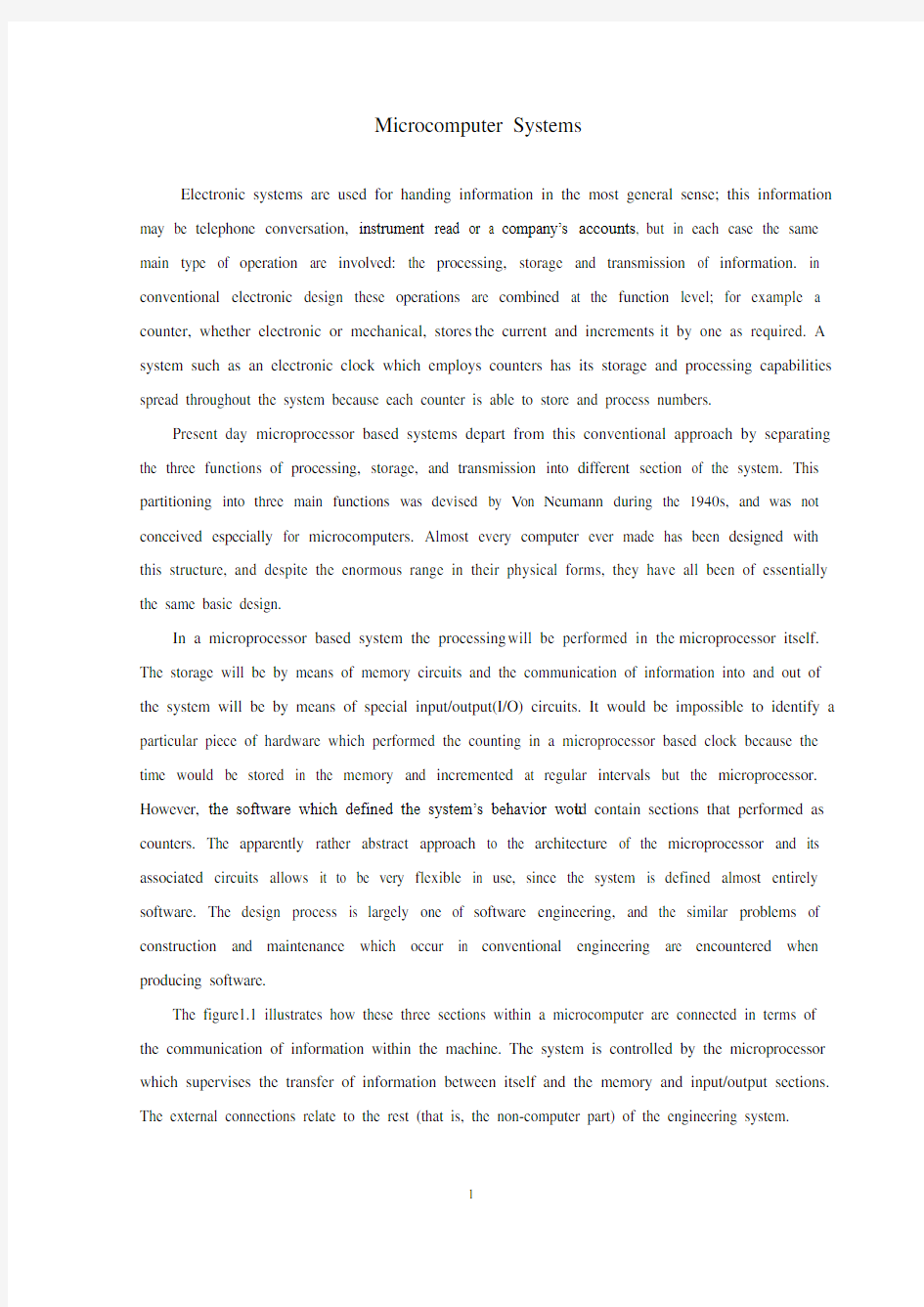
The figure1.1 illustrates how these three sections within a microcomputer are connected in terms of the communication of information within the machine. The system is controlled by the microprocessor which supervises the transfer of information between itself and the memory and input/output sections. The external connections relate to the rest (that is, the non-computer part) of the engineering system.
Fig.1.1 Three Sections of a Typical Microcomputer
Although only one storage section has been shown in the diagram, in practice two distinct types of memory RAM and ROM are used. In each case, the word …memory? is rather inappropriate since a computers memory is more like a filing cabinet in concept; information is stored in a set of numbered …boxes? and it is referenced by the serial number of the …box? in question.
Microcomputers use RAM (Random Access Memory) into which data can be written and from which data can be read again when needed. This data can be read back from the memory in any sequence desired, and not necessarily the same order in which it was written, hence the expression …random? access memory. Another type of ROM (Read Only Memory) is used to hold fixed patterns of information which cannot be affected by the microprocessor; these patterns are not lost when power is removed and are normally used to hold the program which defines the behavior of a microprocessor based system. ROMs can be read like RAMs, but unlike RAMs they cannot be used to store variable information. Some ROMs have their data patterns put in during manufacture, while others are programmable by the user by means of special equipment and are called programmable ROMs. The widely used programmable ROMs are erasable by means of special ultraviolet lamps and are referred to as EPROMs, short for Erasable Programmable Read Only Memories. Other new types of device can be erased electrically without the need for ultraviolet light, which are called Electrically Erasable Programmable Read Only Memories, EEPROMs.
The microprocessor processes data under the control of the program, controlling the flow of information to and from memory and input/output devices. Some input/output devices are general-purpose types while others are designed for controlling special hardware such as disc drives or controlling information transmission to other computers. Most types of I/O devices are programmable to some extent, allowing different modes of operation, while some actually contain special-purpose microprocessors to permit quite complex operations to be carried out without directly involving the main microprocessor.
The microprocessor processes data under the control of the program, controlling the flow of
information to and from memory and input/output devices. Some input/output devices are general-purpose types while others are designed for controlling special hardware such as disc drives or controlling information transmission to other computers. Most types of I/O devices are programmable to some extent, allowing different modes of operation, while some actually contain special-purpose microprocessors to permit quite complex operations to be carried out without directly involving the main microprocessor.
The microprocessor , memory and input/output circuit may all be contained on the same integrated circuit provided that the application does not require too much program or data storage . This is usually the case in low-cost application such as the controllers used in microwave ovens and automatic washing machines . The use of single package allows considerable cost savings to e made when articles are manufactured in large quantities . As technology develops , more and more powerful processors and larger and larger amounts of memory are being incorporated into single chip microcomputers with resulting saving in assembly costs in the final products . For the foreseeable future , however , it will continue to be necessary to interconnect a number of integrated circuits to make a microcomputer whenever larger amounts of storage or input/output are required.
Another major engineering application of microcomputers is in process control. Here the presence of the microcomputer is usually more apparent to the user because provision is normally made for programming the microcomputer for the particular application. In process control applications the benefits lf fitting the entire system on to single chip are usually outweighed by the high design cost involved, because this sort lf equipment is produced in smaller quantities. Moreover, process controllers are usually more complicated so that it is more difficult to make them as single integrated circuits. Two approaches are possible; the controller can be implemented as a general-purpose microcomputer rather like a more robust version lf a hobby computer, or as a …packaged? system, signed for replacing controllers based on older technologies such as electromagnetic relays. In the former case the system would probably be programmed in conventional programming languages such as the ones to9 be introduced later, while in the other case a special-purpose language might be used, for example one which allowed the function of the controller to be described in terms of relay interconnections, In either case programs can be stored in RAM, which allows them to be altered to suit changes in application, but this makes the overall system vulnerable to loss lf power unless batteries are used to ensure continuity of supply. Alternatively programs can be stored in ROM, in which case they virtually become part of the electronic …hardware? and are often referred to as firmware. More sophisticated process controllers
require minicomputers for their implementation, although the use lf large scale integrated circuits …the distinction between mini and microcomputers, Products and process controllers of various kinds represent the majority of present-day microcomputer applications, the exact figures depending on one?s interpretation of the word …product?. Virtually all engineering and scientific uses of microcomputers can be assigned to one or other of these categories. But in the system we most study Pressure and Pressure Transmitters. Pressure arises when a force is applied over an area. Provided the force is one Newton and uniformly over the area of one square meters, the pressure has been designated one Pascal. Pressure is a universal processing condition. It is also a condition of life on the planet: we live at the bottom of an atmospheric ocean that extends upward for many miles. This mass of air has weight, and this weight pressing downward causes atmospheric pressure. Water, a fundamental necessity of life, is supplied to most of us under pressure. In the typical process plant, pressure influences boiling point temperatures, condensing point temperatures, process efficiency, costs, and other important factors. The measurement and control of pressure or lack of it-vacuum-in the typical process plant is critical.
The working instruments in the plant usually include simple pressure gauges, precision recorders and indicators, and pneumatic and electronic pressure transmitters. A pressure transmitter makes a pressure measurement and generates either a pneumatic or electrical signal output that is proportional to the pressure being sensed.
In the process plant, it is impractical to locate the control instruments out in the place near the process. It is also true that most measurements are not easily transmitted from some remote location. Pressure measurement is an exception, but if a high pressure of some dangerous chemical is to be indicated or recorded several hundred feet from the point of measurement, a hazard may be from the pressure or from the chemical carried.
To eliminate this problem, a signal transmission system was developed. This system is usually either pneumatic or electrical. And control instruments in one location. This makes it practical for a minimum number of operators to run the plant efficiently.
When a pneumatic transmission system is employed, the measurement signal is converted into pneumatic signal by the transmitter scaled from 0 to 100 percent of the measurement value. This transmitter is mounted close to the point of measurement in the process. The transmitter output-air pressure for a pneumatic transmitter-is piped to the recording or control instrument. The standard output range for a pneumatic transmitter is 20 to 100kPa, which is almost universally used.
When an electronic pressure transmitter is used, the pressure is converted to electrical signal that
may be current or voltage. Its standard range is from 4 to 20mA DC for current signal or from 1 to 5V DC for voltage signal. Nowadays, another type of electrical signal, which is becoming common, is the digital or discrete signal. The use of instruments and control systems based on computer or forcing increased use of this type of signal.
Sometimes it is important for analysis to obtain the parameters that describe the sensor/transmitter behavior. The gain is fairly simple to obtain once the span is known. Consider an electronic pressure transmitter with a range of 0~600kPa.The gain is
defined as the change in output divided by the change in input. In this case, the output is electrical signal (4~20mA DC) and the input is process pressure (0~600kPa). Thus the gain. Beside we must measure Temperature Temperature measurement is important in industrial control, as direct indications of system or product state and as indirect indications of such factors as reaction rates, energy flow, turbine efficiency, and lubricant quality. Present temperature scales have been in use for about 200 years, the earliest instruments were based on the thermal expansion of gases and liquids. Such filled systems are still employed, although many other types of instruments are available. Representative temperature sensors include: filled thermal systems, liquid-in-glass thermometers, thermocouples, resistance temperature detectors, thermostats, bimetallic devices, optical and radiation pyrometers and temperature-sensitive paints.
Advantages of electrical systems include high accuracy and sensitivity, practicality of switching or scanning several measurements points, larger distances possible between measuring elements and controllers, replacement of components(rather than complete system), fast response, and ability to measure higher temperature. Among the electrical temperature sensors, thermocouples and resistance temperature detectors are most widely used.
Description
The A T89C51 is a low-power, high-performance CMOS 8-bit microcomputer with 4K bytes of Flash programmable and erasable read only memory (PEROM). The device is manufactur ed using Atmel?s high-density nonvolatile memory technology and is compatible with the industry-standard MCS-51 instruction set and pinout. The on-chip Flash allows the program memory to be reprogrammed in-system or by a conventional nonvolatile memory programmer. By combining a versatile 8-bit CPU
kPa
mA kPa mA kPa kPa mA mA Kr 027.0600160600420==--=
with Flash on a monolithic chip, the Atmel AT89C51 is a powerful microcomputer which provides a highly-flexible and cost-effective solution to many embedded control applications.
Function characteristic
The A T89C51 provides the following standard features: 4K bytes of Flash, 128 bytes of RAM, 32 I/O lines, two 16-bit timer/counters, a five vector two-level interrupt architecture, a full duplex serial port, on-chip oscillator and clock circuitry. In addition, the AT89C51 is designed with static logic for operation down to zero frequency and supports two software selectable power saving modes. The Idle Mode stops the CPU while allowing the RAM, timer/counters, serial port and interrupt system to continue functioning. The Power-down Mode saves the RAM contents but freezes the oscillator disabling all other chip functions until the next hardware reset.
Pin Description
VCC:Supply voltage.
GND:Ground.
Port 0:
Port 0 is an 8-bit open-drain bi-directional I/O port. As an output port, each pin can sink eight TTL inputs. When 1s are written to port 0 pins, the pins can be used as highimpedance inputs.Port 0 may also be configured to be the multiplexed loworder address/data bus during accesses to external program and data memory. In this mode P0 has internal pullups.Port 0 also receives the code bytes during Flash programming,and outputs the code bytes during programverification. External pullups are required during programverification.
Port 1
Port 1 is an 8-bit bi-directional I/O port with internal pullups.The Port 1 output buffers can sink/source four TTL inputs.When 1s are written to Port 1 pins they are pulled high by the internal pullups and can be used as inputs. As inputs,Port 1 pins that are externally being pulled low will source current (IIL) because of the internal pullups.Port 1 also receives the low-order address bytes during Flash programming and verification.
Port 2
Port 2 is an 8-bit bi-directional I/O port with internal pullups.The Port 2 output buffers can sink/source four TTL inputs.When 1s are written to Port 2 pins they are pulled high by the internal pullups and can
be used as inputs. As inputs,Port 2 pins that are externally being pulled low will source current, because of the internal pullups.Port 2 emits the high-order address byte during fetches from external program memory and during accesses to external data memory that use 16-bit addresses. In this application, it uses strong internal pullupswhen emitting 1s. During accesses to external data memory that use 8-bit addresses, Port 2 emits the contents of the P2 Special Function Register.Port 2 also receives the high-order address bits and some control signals during Flash programming and verification.
Port 3
Port 3 is an 8-bit bi-directional I/O port with internal pullups.The Port 3 output buffers can sink/source four TTL inputs.When 1s are written to Port 3 pins they are pulled high by the internal pullups and can be used as inputs. As inputs,Port 3 pins that are externally being pulled low will source current (IIL) because of the pullups.Port 3 also serves the functions of various special features of the AT89C51 as listed below:
Port 3 also receives some control signals for Flash programming and verification.
RST
Reset input. A high on this pin for two machine cycles while the oscillator is running resets the device. ALE/PROG
Address Latch Enable output pulse for latching the low byte of the address during accesses to external memory. This pin is also the program pulse input (PROG) during Flash programming.In normal operation ALE is emitted at a constant rate of 1/6 the oscillator frequency, and may be used for external timing or clocking purposes. Note, however, that one ALE pulse is skipped during each access to external Data Memory.
If desired, ALE operation can be disabled by setting bit 0 of SFR location 8EH. With the bit set, ALE is active only during a MOVX or MOVC instruction. Otherwise, the pin is weakly pulled high. Setting the ALE-disable bit has no effect if the microcontroller is in external execution mode.
PSEN
Program Store Enable is the read strobe to external program memory.When the AT89C51 is executing code from external program memory, PSEN is activated twice each machine cycle, except that two PSEN activations are skipped during each access to external data memory.
EA/VPP
External Access Enable. EA must be strapped to GND in order to enable the device to fetch code from external program memory locations starting at 0000H up to FFFFH. Note, however, that if lock bit 1 is programmed, EA will be internally latched on reset.EA should be strapped to VCC for internal program executions.This pin also receives the 12-volt programming enable voltage(VPP) during Flash programming, for parts that require12-volt VPP.
XTAL1
Input to the inverting oscillator amplifier and input to the internal clock operating circuit.
XTAL2
Output from the inverting oscillator amplifier.
Oscillator Characteristics
XTAL1 and XTAL2 are the input and output, respectively,of an inverting amplifier which can be configured for use as an on-chip oscillator, as shown in Figure 1.Either a quartz crystal or ceramic resonator may be used. To drive the device from an external clock source, XTAL2 should be left unconnected while XTAL1 is driven as shown in Figure 2.There are no requirements on the duty cycle of the external clock signal, since the input to the internal clocking circuitry is through a divide-by-two flip-flop, but minimum and maximum voltage high and low time specifications must be observed.
微型计算机控制系统(单片机控制系统)
广义地说,微型计算机控制系统(单片机控制系统)是用于处理信息的,这种被用于处理的信息可以是电话交谈,也可以是仪器的读数或者是一个企业的帐户,但是各种情况下都涉及到相同的主要操作:信息的处理、信息的存储和信息的传递。在常规的电子设计中,这些操作都是以功能平台方式组合起来的,例如计数器,无论是电子计数器还是机械计数器,都要存储当前的数值,并且按要求将该数值增加1。一个系统例如采用计数器的电子钟之类的任一系统要使其存储和处理能力遍布整个系统,因为每个计数器都能存储和处理一些数字。
现如今,以微处理器为基础的系统从常规的处理方法中分离了出来,它将信息的
处理,信息的存储和信息的传输三个功能分离形成不同的系统单元。这种主要将系统分成三个主要单元的分离方法是冯-诺依曼在20世纪40年代所设想出来的,并且是针对微计算机的设想。从此以后基本上所有制成的计算机都是用这种结构设计的,尽管他们包含着宽广的物理形式与物理结构,但从根本上来说他们均是具有相同基本设计的计算机。
在以微处理器为基础的系统中,处理是由以微处理器为基础的系统自身完成的。存储是利用存储器电路,而从系统中输入和输出的信息传输则是利用特定的输入/输出(I/O)电路。要在一个以微处理器为基础的时钟中找出执行具有计数功能的一个特殊的硬件组成部分是不可能的,因为时间存储在存储器中,而在固定的时间间隔下由微处理器控制增值。但是,规定系统运转过程的软件却规定了包含实现计数器计数功能的单元部分。由于系统几乎完全由软件所定义,所以对微处理器结构和其辅助电路这种看起来非常抽象的处理方法使其在应用时非常灵活。这种设计过程主要是软件工程,而且在生产软件时,就会遇到产生于常规工程中相似的构造和维护问题。
图1.1 微型计算机的三个组成部分
图1.1显示出了微型计算机中这三个单元在一个微处理器控制系统中是如何按照机器中的信息通信方式而联接起来的。该系统由微处理器控制,微处理器能够对其自身的存储器和输入/输出单元的信息传输进行管理。外部的连接部分与工程系统中的其余部分(即非计算机部分)有关。
尽管图中显示的只有一个存储单元,但是在实际中却有RAM和ROM两种不同的存储器被使用。在每一种情况下,由于概念上的计算机存储器更像一个公文柜,上述的“存储器”一词是非常不恰当的;信息被存放在一系列已数字标记过的的“箱子”中,而且可以按照问题由“箱子”的序列号进行相关信息的参考定位。
微计算机控制系统经常使用RAM(随机存取存储器),在RAM中,数据可以被写入,并且在需要的时候,可以被再次读出。这种数据能以任意一种所希望的次序从存储器中读出,而不必按照写入时的相同次序读出,所以有“随机”存取存储器。另一类型ROM(只读存储器)是用来保持信息的,它们是不受微处理器影响的固定的信息标本;这些信息在电源切断后不会丢失,并通常用来保存规定微处理器化系统运转
过程的程序。ROM可像RAM一样被读取,但与RAM不一样的是不能用来存储可变的信息。有些ROM在制造时将其数据标本放入,而另外的则可通过特殊的设备由用户编程,所以称为可编程ROM。被广泛使用的可编程ROM可利用特殊紫外线灯察除,并被成为E
PROM,即可察除可编程只读存储器的缩写。另有新类型的期器件不必用紫外线灯而用电察除,所以称为电可察除可编程只读存储器EEPROM。
微处理器在程序控制下处理数据,并控制流向和来自存储器和输入/输出装置的信息流。有些输入/输出装置是通用型的,而另外一些则是设计来控制如磁盘驱动器的特殊硬件,或控制传给其他计算机的信息传输。大多数类型的I/O装置在某种程度下可编程,允许不同形式的操作,而有些则包含特殊用途微处理器的I/O装置不用主微处理器的直接干预,就可实施非常复杂的操作。
假如应用中不需要太多的程序和数据存储量,微处理器、存储器和输入/输出可全被包含在同一集成电路中。这通常是低成本应用情况,例如用于微波炉和自动洗衣机的控制器。当商品被大量地生产时,这种单一芯片的使用就可节省相当大的成本。当技术进一步发展,更强更强的处理器和更大更大数量的存储器被包含形成单片微型计算机,结果使最终产品的装配成本得以节省。但是在可预见的未来,当需要大量的存储器或输入/输出时,还是有必要继续将许多集成电路相互联结起来,形成微计算机。
微计算机的另一主要工程应用是在过程控制中。这是,由于装置是按特定的应用情况由微机编程实现的,对用户来说微计算机的存在通常就更加明显。在过程控制应用中,由于这种设备以较少的数量生产,将整个系统安装在单个芯片上所获取的利益常比不上所涉及的高设计成本。而且,过程控制器通常更为复杂,所以要将他们做成单独的集成电路就更为困难。可采用两种处理,将控制器做成一种通用的微计算机,正像较强版本的业余计算机那样;或者做成“包裹”式系统,按照像电磁继电器那样的较老式的技术进行设计,来取代控制器。对前一种情况,系统可以用常规的编程语言来编程,正如以后要介绍的语言那样;而另一种情况,可采用特殊用途的语言,例如那种使控制器功能按照继电器相互连接的方法进行描述。两种情况下,序均能存于RAM,这让程序能按应用情况变化时进行相应的变化,但是这使得总系统易受掉电影响而工作不正常,除非使用电池保证供电连续性。另一种选择是将程序在ROM中,这样他们就变成电子“硬件”的一部分并常被称为“固件”。
尽管大规模集成电路的应用使小型和微型计算机的差别变得“模糊”,更复杂的
过程控制器需要小型计算机实现他们的过程。各种类型的产品和过程控制器代表了当今微计算机应用的广泛性,而具体的结构取决于对“产品”一词的解释。实际上,计算机的所有工程和科学上的应用都能指定来进行这些种类的某一或某些工作。而在本设计中压力和压力变送器当某一力加到某一面积上,就形成压力,假如这力是1牛顿均匀地加在1平方米的面积上,这压力被定义为1帕斯卡。压力是一种普遍的工艺状态,它也是这个星球上的一个生活条件:我们生活在向上延伸许多英里的大气海洋的底部。空气物质是有重量的,而且这种下压的重量形成大气压。水,是生活的必需品,也是在压力之下提供给我们中的大多数人。在典型的过程工厂中,压力影响沸点温度、凝固点温度、过程效率、消耗和其他重要因数。压力的测量和控制,或者压力的不足—真空,在典型的过程控制中是极为重要的。
工厂中的工作仪器通常包括压力计、精密纪录仪、以及气动和电动的压力变送器。压力变送器实现压力测量并产生正比于所传感压力的气动或电信号输出。
在过程工厂中,将控制仪表远远放在过程的附近是不现实的,并且大多数测量是不容易从远处传来的。压力测量是一个例外,但是,如果要离测量点几百英尺外指示或记录某种危险化学品的高压,就会有来自这个压力所载的化学品所引发的危险。为了消除这一问题,开发了一种信号传输系统。这种系统常常可是气动或者电动的。使用这种系统,就可以在某一地点安装大多数的指示、记录和控制仪器。这也是最少数量的操作者有效的运行工厂成为现实。
当使用气动传送系统时,测量信号就由变送器将比例为0%~100%的测量值转换为气动信号。变送器安装在靠近过程中的测量点上。变送器输出—对气动变送器是输出压力—通过管道传给记录或控制仪表。气动变送器的标准输出范围是20~100kPa,这信号几乎在全球使用。
当使用电子压力变送器时,压力就被转换成电流或电压形式的电信号。其标准范围对电流来说是4~20mA DC,对电压信号来说是1~5V DC。当今,另一种电信号形式变的越来越常用,就是数字或离散信号。基于计算机或微处理器的仪器或控制系统的应用正推动这类信号的应用不断增加。有时,分析获取描述传感器/变送器特性的参数是很重要的。当量程已知,去获取增益就非常简单。假定电子压力传感器的量程为0~600kPa,增益定义为输出变化除以输入变化。这里,输出的电信号(4~20mA DC),而输入的过程压力(0~600kPa),这样增益就为:
此外我们在本设计中还必须对温度进行测量,温度测量在工业控制中是很重要的,因为它作为系统或产品状态的直接指标,或者作为如反应率、能量流、涡轮机效率和润滑质量等间接指标。现行的温度分度已使用了约200年,最初的仪器是基于气体和液体的热膨胀。现在尽管有许多其他类型的仪器在使用,这些填充式系统仍常用于直接的温度测量。有代表性的温度传感器包括:填充式热系统、玻璃液体温度计、热电偶、电阻温度探测器、热敏电阻、双金属器件、光学和辐射高温计和热敏涂料。
电气系统的优点包括高的精度和灵敏度,能实现开关切换或扫描多个测量点,可在测量元件和控制器之间长距离传输,出现事故时可调换元件,快速响应,以及具有测量高温的能力。其中热电偶和电阻温度探测器则被最广泛的使用。
说明
该AT89C51是一种低功耗,高性能CMOS 8位4K 的闪存可编程和可擦除只读存储器(PEROM )字节的微型计算机。该设备是采用Atmel 的高密度非易失性内存技术,并与行业标准的MCS - 51指令集和引脚兼容。片上闪存程序存储器可以编程就可以在系统或由传统的非易失性存储器编程。通过将集成在一个芯片上通用的8位闪存的CPU ,Atmel 的AT89C51是一个强大的微型计算机提供了一个高度灵活和成本有效的解决方案为许多嵌入式控制应用。
功能特点
AT89S51内提供了以下标准特性:4K 字节闪存,128字节RAM ,32个I / O 线,两个16位定时器/计数器,一个五向量两级中断结构,一个全双工串行口,片上振荡器和时钟电路。此外,AT89C51是静态逻辑设计与操作频率下降到零,并支持两种软件可选的节电模式。空闲模式时CPU 停止工作,而RAM ,定时/计数器,串行口和中断系统继续工作。掉电模式保存RAM 的内容,但冻结振荡器关闭,直到下一个硬件复位芯片其它功能。
引脚说明
Vcc :电源电压。
接地:接地。
P0口:
kPa
mA kPa mA kPa kPa mA mA Kr 027.0600160600420==--=
P0口为一个8位漏级开路双向I/O口,每脚可吸收8TTL门电流。当P0口的管脚第一次写1时,被定义为高阻输入。P0能够用于外部程序数据存储器,它可以被定义为数据/地址的第八位。在FIASH编程时,P0 口作为原码输入口,当FIASH进行校验时,P0输出原码,此时P0外部必须被拉高。
P1口:
P1口是一个内部提供上拉电阻的8位双向I/O口,P1口缓冲器能接收输出4TTL 门电流。P1口管脚写入1后,被内部上拉为高,可用作输入,P1口被外部下拉为低电平时,将输出电流,这是由于内部上拉的缘故。在FLASH编程和校验时,P1口作为第八位地址接收。
P2口:
P2口为一个内部上拉电阻的8位双向I/O口,P2口缓冲器可接收,输出4个TTL 门电流,当P2口被写“1”时,其管脚被内部上拉电阻拉高,且作为输入。并因此作为输入时,P2口的管脚被外部拉低,将输出电流。这是由于内部上拉的缘故。P2口当用于外部程序存储器或16位地址外部数据存储器进行存取时,P2口输出地址的高八位。在给出地址“1”时,它利用内部上拉优势,当对外部八位地址数据存储器进行读写时,P2口输出其特殊功能寄存器的内容。P2口在FLASH编程和校验时接收高八位地址信号和控制信号。
P3口:
P3口管脚是8个带内部上拉电阻的双向I/O口,可接收输出4个TTL门电流。当P3口写入“1”后,它们被内部上拉为高电平,并用作输入。作为输入,由于外部下拉为低电平,P3口将输出电流(ILL)这是由于上拉的缘故。
RST
复位输入。此管脚上出现两个机器周期的高电平,而振荡器运行将使器件复位。
进修/编
地址锁存使能锁存在访问外部存储器地址的低字节输出脉冲。该引脚也是在flash编程脉冲输入programming.In正常运行的ALE(编)是在1 / 6振荡器频率恒定的速率发射,并可能对外部定时或时钟的用途。请注意,但是,一个ALE脉冲被跳过在每次访问外部数据存储器。
如果需要时,ALE操作可以通过设置位SFR的位置8EH 0。随着位设置,ALE为活跃,只有在执行MOVX或MOVC指令。否则,脚弱拉高。设置的ALE -禁用位微控
制器没有影响,如果在外部执行模式。
ALE/PROG:当访问外部存储器时,地址锁存允许的输出电平用于锁存地址的地位字节。在FLASH编程期间,此引脚用于输入编程脉冲。在平时,ALE端以不变的频率周期输出正脉冲信号,此频率为振荡器频率的1/6。因此它可用作对外部输出的脉冲或用于定时目的。然而要注意的是:每当用作外部数据存储器时,将跳过一个ALE脉冲。如想禁止ALE的输出可在SFR8EH地址上置0。此时,ALE只有在执行MOVX,MOVC指令是ALE才起作用。另外,该引脚被略微拉高。如果微处理器在外部执行状态ALE禁止,置位无效。
PSEN:外部程序存储器的选通信号。在由外部程序存储器取指期间,每个机器周期两次/PSEN有效。但在访问外部数据存储器时,这两次有效的/PSEN信号将不出现。
EA/VPP:当/EA保持低电平时,则在此期间外部程序存储器(0000H-FFFFH),不管是否有内部程序存储器。注意加密方式1时,/EA将内部锁定为RESET;当/EA 端保持高电平时,此间内部程序存储器。在FLASH编程期间,此引脚也用于施加12V 编程电源(VPP)。
XTAL1:反向振荡放大器的输入及内部时钟工作电路的输入。XTAL2:来自反向振荡器的输出。
振荡器特性:XTAL1和XTAL2分别为反向放大器的输入和输出。该反向放大器可以配置为片内振荡器。石晶振荡和陶瓷振荡均可采用。如采用外部时钟源驱动器件,XTAL2应不接。有余输入至内部时钟信号要通过一个二分频触发器,因此对外部时钟信号的脉宽无任何要求,但必须保证脉冲的高低电平要求的宽度。
冲压模具技术外文翻译(含外文文献)
前言 在目前激烈的市场竞争中,产品投入市场的迟早往往是成败的关键。模具是高质量、高效率的产品生产工具,模具开发周期占整个产品开发周期的主要部分。因此客户对模具开发周期要求越来越短,不少客户把模具的交货期放在第一位置,然后才是质量和价格。因此,如何在保证质量、控制成本的前提下加工模具是值得认真考虑的问题。模具加工工艺是一项先进的制造工艺,已成为重要发展方向,在航空航天、汽车、机械等各行业得到越来越广泛的应用。模具加工技术,可以提高制造业的综合效益和竞争力。研究和建立模具工艺数据库,为生产企业提供迫切需要的高速切削加工数据,对推广高速切削加工技术具有非常重要的意义。本文的主要目标就是构建一个冲压模具工艺过程,将模具制造企业在实际生产中结合刀具、工件、机床与企业自身的实际情况积累得高速切削加工实例、工艺参数和经验等数据有选择地存储到高速切削数据库中,不但可以节省大量的人力、物力、财力,而且可以指导高速加工生产实践,达到提高加工效率,降低刀具费用,获得更高的经济效益。 1.冲压的概念、特点及应用 冲压是利用安装在冲压设备(主要是压力机)上的模具对材料施加压力,使其产生分离或塑性变形,从而获得所需零件(俗称冲压或冲压件)的一种压力加工方法。冲压通常是在常温下对材料进行冷变形加工,且主要采用板料来加工成所需零件,所以也叫冷冲压或板料冲压。冲压是材料压力加工或塑性加工的主要方法之一,隶属于材料成型工程术。 冲压所使用的模具称为冲压模具,简称冲模。冲模是将材料(金属或非金属)批量加工成所需冲件的专用工具。冲模在冲压中至关重要,没有符合要求的冲模,批量冲压生产就难以进行;没有先进的冲模,先进的冲压工艺就无法实现。冲压工艺与模具、冲压设备和冲压材料构成冲压加工的三要素,只有它们相互结合才能得出冲压件。 与机械加工及塑性加工的其它方法相比,冲压加工无论在技术方面还是经济方面都具有许多独特的优点,主要表现如下; (1) 冲压加工的生产效率高,且操作方便,易于实现机械化与自动化。这是
自动化系毕业设计外文翻译(中英文对照)
吉林化工学院信息与控制工程学院 毕业设计外文翻译 基于WINCC自动洗车监控系统设计 Design of Automatic Vehicle Cleaning Simulation System Based on WinCC 学生学号:08510234 学生姓名:李洪敏 专业班级:自动0904 指导教师:姜德龙 职称:教授 起止日期:2013.03.04~2013.03.19 吉林化工学院 Jilin Institute of Chemical Technology
一个成功的控制系统革新的策略 ——在升级的时候考虑这些指导方针 用最近的最新颖的系统升级一个主要的传统类型的控制系统是任何过程工业得到竞争力的关键。改良任何的系统主要目的是为了要有适当的连接性和互通性来增加灵活性和连续性的功能。 在这里提供的指导方针向指出了在一个如此富有挑战性的工程后面的主要问题。为了及时的和有成本效益的完成,要从概念上的计划上跟随它们。这些建议考虑了限制、假定和附加的研究来解决在整个工程中的一步步活动:设计、采购、构造和委任期间的全部预期问题。 为控制系统升级的需要。当升级一个传统的控制系统为一个集散控制系统(DCS)的时候,目标是: ●提供基于高度的分配机器智能的一个复杂的过程控制系统,供应有效的控 制和包罗万象的操作员接口。 ●保证那在低消耗下具有实时操作的新的集散控制系统(DCS)的高可靠性。 ●保证对工厂操作所必需的数据获取和程序数据设置的快速响应。有与任何 其他的最新颖的系统兼容的开放式结构。这允许过程控制和自动化系统整 合的最高程度,这些自动化系统有一个对各种厂商独立的并且公开分配的 接口的规格。 ●通过对工厂的关键区段/叁数的管理控制来提供工厂自动化。 ●可行性研究应该应该在升级现存的控制系统到集散控制系统(DCS)之前被 实行。所有的理由,无论是系统的、一些装置的或元件的,都要被证明。目 的包括: ●执行基于预先准备的关于对现存系统的恶化和荒废的报告的可行性研究。 ●检查现存的控制系统的线路板的寿命。它被通常估计从安装日期起是大约 15年。这可能造成依照每个控制/检测回路的临界一步步替换线路板的紧急 计划。 ●升级控制系统是艺术级的。通过有一个减少了硬件成份的高度可靠的系统, 丢弃陈旧的仪器,将会减少维护和操作的费用。 ●通过包括较多的厂商和征求最好的提议用最小的价格达成全部的需求。
步进电机及单片机英文文献及翻译
外文文献: Knowledge of the stepper motor What is a stepper motor: Stepper motor is a kind of electrical pulses into angular displacement of the implementing agency. Popular little lesson: When the driver receives a step pulse signal, it will drive a stepper motor to set the direction of rotation at a fixed angle (and the step angle). You can control the number of pulses to control the angular displacement, so as to achieve accurate positioning purposes; the same time you can control the pulse frequency to control the motor rotation speed and acceleration, to achieve speed control purposes. What kinds of stepper motor sub-: In three stepper motors: permanent magnet (PM), reactive (VR) and hybrid (HB) permanent magnet stepper usually two-phase, torque, and smaller, step angle of 7.5 degrees or the general 15 degrees; reaction step is generally three-phase, can achieve high torque output, step angle of 1.5 degrees is generally, but the noise and vibration are large. 80 countries in Europe and America have been eliminated; hybrid stepper is a mix of permanent magnet and reactive advantages. It consists of two phases and the five-phase: two-phase step angle of 1.8 degrees while the general five-phase step angle of 0.72 degrees generally. The most widely used Stepper Motor. What is to keep the torque (HOLDING TORQUE) How much precision stepper motor? Whether the cumulative: The general accuracy of the stepper motor step angle of 3-5%, and not cumulative.
控制系统基础论文中英文资料外文翻译文献
控制系统基础论文中英文资料外文翻译文献 文献翻译 原文: Numerical Control One of the most fundamental concepts in the area of advanced manufacturing technologies is numerical control (NC).Prior to the advent of NC, all machine tools were manual operated and controlled. Among the many limitations associated with manual control machine tools, perhaps none is more prominent than the limitation of operator skills. With manual control, the quality of the product is directly related to and limited to the skills of the operator . Numerical control represents the first major step away from human control of machine tools. Numerical control means the control of machine tools and other manufacturing systems though the use of prerecorded, written symbolic instructions. Rather than operating a machine tool, an NC technician writes a program that issues operational instructions to the machine tool, For a machine tool to be numerically controlled , it must be interfaced with a device for accepting and decoding the p2ogrammed instructions, known as a reader. Numerical control was developed to overcome the limitation of human operator , and it has done so . Numerical control machines are more accurate than manually operated machines , they can produce parts more uniformly , they are faster, and the long-run tooling costs are lower . The development of NC led to the development of several other innovations in manufacturing technology: 1.Electrical discharge machining. https://www.360docs.net/doc/3a13308922.html,ser cutting. 3.Electron beam welding.
机械设计外文翻译(中英文)
机械设计理论 机械设计是一门通过设计新产品或者改进老产品来满足人类需求的应用技术科学。它涉及工程技术的各个领域,主要研究产品的尺寸、形状和详细结构的基本构思,还要研究产品在制造、销售和使用等方面的问题。 进行各种机械设计工作的人员通常被称为设计人员或者机械设计工程师。机械设计是一项创造性的工作。设计工程师不仅在工作上要有创造性,还必须在机械制图、运动学、工程材料、材料力学和机械制造工艺学等方面具有深厚的基础知识。如前所诉,机械设计的目的是生产能够满足人类需求的产品。发明、发现和科技知识本身并不一定能给人类带来好处,只有当它们被应用在产品上才能产生效益。因而,应该认识到在一个特定的产品进行设计之前,必须先确定人们是否需要这种产品。 应当把机械设计看成是机械设计人员运用创造性的才能进行产品设计、系统分析和制定产品的制造工艺学的一个良机。掌握工程基础知识要比熟记一些数据和公式更为重要。仅仅使用数据和公式是不足以在一个好的设计中做出所需的全部决定的。另一方面,应该认真精确的进行所有运算。例如,即使将一个小数点的位置放错,也会使正确的设计变成错误的。 一个好的设计人员应该勇于提出新的想法,而且愿意承担一定的风险,当新的方法不适用时,就使用原来的方法。因此,设计人员必须要有耐心,因为所花费的时间和努力并不能保证带来成功。一个全新的设计,要求屏弃许多陈旧的,为人们所熟知的方法。由于许多人墨守成规,这样做并不是一件容易的事。一位机械设计师应该不断地探索改进现有的产品的方法,在此过程中应该认真选择原有的、经过验证的设计原理,将其与未经过验证的新观念结合起来。 新设计本身会有许多缺陷和未能预料的问题发生,只有当这些缺陷和问题被解决之后,才能体现出新产品的优越性。因此,一个性能优越的产品诞生的同时,也伴随着较高的风险。应该强调的是,如果设计本身不要求采用全新的方法,就没有必要仅仅为了变革的目的而采用新方法。 在设计的初始阶段,应该允许设计人员充分发挥创造性,不受各种约束。即使产生了许多不切实际的想法,也会在设计的早期,即绘制图纸之前被改正掉。只有这样,才不致于堵塞创新的思路。通常,要提出几套设计方案,然后加以比较。很有可能在最后选定的方案中,采用了某些未被接受的方案中的一些想法。
集散控制系统
直接数字控制系统 现场总线控制系统 实时控制 传输速率 计算机控制系统 集散控制系统 现场总线 组态 串行传输 通信协议 监督计算机控制系统 分级控制系统 模拟通信 数字通信 并行传输 开放系统互连参考模型 数字滤波: 实时 三、单项选择题 1. TDC3000系统进行NCF组态时,每个系统可以定义()个单元。 (A)24 (B)100 (C)36 (D)64 2. TDC3000系统进行NCF组态时,每个系统可以定义()个区域。 (A)24 (B)10 (C)36 (D)64 3. TDC3000系统运行中,HM 如出现故障,可能会影响()。
(A) 控制功能运行 (B) 流程图操作 (C) 键盘按键操作 (D) 以上3种情况都有 4. TDC3000系统运行中,在HM 不可以进行如下操作()。 (A) 格式化卡盘 (B) 流程图文件复制 (C) 删除系统文件 (D) 删除用户文件 5. TDC3000系统中,HPMM 主要完成以下功能()。 (A) 控制处理和通讯 (B) 控制点运算 (C) 数据采集处理 (D) 逻辑控制 6. TDC3000系统中,每个HPM 可以有()卡笼箱。 (A) 8个 (B) 6个 (C) 3个 (D) 没有数量限制 7. TDC3000系统中,当IOP卡件(如AI卡)的状态指示灯闪烁时,表示此卡件存在()。 (A) 通信故障 (B) 现场输入/输出参数超量程报警(C) 软故障(D) 硬件故障 8. TDC3000系统中,若有一组AO卡为冗余配置,当其中一个AO卡状态指示灯灭时,其对应FTA 的输出应为()。 (A) 输出为100,对应现场为20mA (B) 正常通信 (C) 输出为设定的安全值 (D) 输出为0,对应现 场为4mA 9.TDC3000系统中,HLAI为高电平模拟量输入卡,不可以接收()信号。 (A) 24VDC信号(B) 4-20mA信号(C) 1-5V信号 (D) 0-100mv信号 10. TDC3000系统中,若有一组DI卡为冗余配置,则其对应的FTA应为()。 (A) 不冗余配置(B) 冗余配置(C) 由工艺重要性确定是否冗余配置 (D) 由控制工程师确定是否冗 余配置 11. TDC3000/TPS系统中,每个LCN系统可以定义()个AREA区域。 (A) 36 (B) 100 (C) 20 (D) 10 12.TDC3000/TPS系统中,操作员的操作权限是通过()的划分来限制的。 (A) UNIT单元(B) HPM硬件 (C) AREA区域 (D) 由工艺流程岗位 13. TDC3000/TPS系统中,每个AREA区域可以定义()个操作组。 (A) 390 (B) 400 (C) 450 (D) 20 14. TDC3000/TPS系统中,操作员在操作组画面上不可以进行下列()操作。
单片机外文翻译
杭州电子科技大学信息工程学院毕业设计(论文)外文文献翻译 毕业设计(论文)题目用单片机实现的数字时钟电路设计文献综述题目单片机控制系统系电子工程 专业电子信息科学与技术 姓名郭筱楠 班级08091911 学号08919115 指导教师王维平
单片机控制系统 广义地说,微型计算机控制系统(单片机控制系统)是用于处理信息的,这种被用于处理的信息可以是电话交谈,也可以是仪器的读数或者是一个企业的帐户,但是各种情况下都涉及到相同的主要操作:信息的处理、信息的存储和信息的传递。在常规的电子设计中,这些操作都是以功能平台方式组合起来的,例如计数器,无论是电子计数器还是机械计数器,都要存储当前的数值,并且按要求将该数值增加1。一个系统例如采用计数器的电子钟之类的任一系统要使其存储和处理能力遍布整个系统,因为每个计数器都能存储和处理一些数字。 现如今,以微处理器为基础的系统从常规的处理方法中分离了出来,它将信息的处理,信息的存储和信息的传输三个功能分离形成不同的系统单元。这种主要将系统分成三个主要单元的分离方法是冯-诺依曼在20世纪40年代所设想出来的,并且是针对微计算机的设想。从此以后基本上所有制成的计算机都是用这种结构设计的,尽管他们包含着宽广的物理形式与物理结构,但从根本上来说他们均是具有相同基本设计的计算机。 在以微处理器为基础的系统中,处理是由以微处理器为基础的系统自身完成的。存储是利用存储器电路,而从系统中输入和输出的信息传输则是利用特定的输入/输出(I/O)电路。要在一个以微处理器为基础的时钟中找出执行具有计数功能的一个特殊的硬件组成部分是不可能的,因为时间存储在存储器中,而在固定的时间间隔下由微处理器控制增值。但是,规定系统运转过程的软件却规定了包含实现计数器计数功能的单元部分。由于系统几乎完全由软件所定义,所以对微处理器结构和其辅助电路这种看起来非常抽象的处理方法使其在应用时非常灵活。这种设计过程主要是软件工程,而且在生产软件时,就会遇到产生于常规工程中相似的构造和维护问题。 图1.1 微型计算机的三个组成部分 图1.1显示出了微型计算机中这三个单元在一个微处理器控制系统中是如何按照机器中的信息通信方式而联接起来的。该系统由微处理器控制,微处理器能够对其自身的存储器和输入/输出单元的信息传输进行管理。外部的连接部分与
基于单片机的步进电机控制系统设计外文翻译
毕业设计(论文)外文资料翻译 学院:机械工程学院 专业:机械设计制造及其自动化 姓名: 学号:XXXXXXXXXX 外文出处:《Computational Intelligence and (用外文写)Design》 附件: 1.外文资料翻译译文;2.外文原文。 注:请将该封面与附件装订成册。
附件1:外文资料翻译译文 基于微型计算机的步进电机控制系统设计 孟天星余兰兰 山东理工大学电子与电气工程学院 山东省淄博市 摘要 本文详细地介绍了一种以AT89C51为核心的步进电机控制系统。该系统设计包括硬件设计、软件设计和电路设计。电路设计模块包括键盘输入模块、LED显示模块、发光二极管状态显示和报警模块。按键可以输入设定步进电机的启停、转速、转向,改变转速、转向等的状态参数。通过键盘输入的状态参数来控制步进电机的步进位置和步进速度进而驱动负载执行预订的工作。运用显示电路来显示步进电机的输入数据和运行状态。AT89C51单片机通过指令系统和编译程序来执行软件部分。通过反馈检测模块,该系统可以很好地完成上述功能。 关键词:步进电机,AT89C51单片机,驱动器,速度控制 1概述 步进电机因为具有较高的精度而被广泛地应用于运动控制系统,例如机器人、打印机、软盘驱动机、绘图仪、机械式阀体等等。过去传统的步进电机控制电路和驱动电路设计方法通常都极为复杂,由成本很高而且实用性很差的电器元件组成。结合微型计算机技术和软件编程技术的设计方法成功地避免了设计大量复杂的电路,降低了使用元件的成本,使步进电机的应用更广泛更灵活。本文步进电机控制系统是基于AT89C51单片机进行设计的,它具有电路简单、结构紧凑的特点,能进行加减速,转向和角度控制。它仅仅需要修改控制程序就可以对各种不同型号的步进电机进行控制而不需要改变硬件电路,所以它具有很广泛的应用领域。 2设计方案 该系统以AT89C51单片机为核心来控制步进电机。电路设计包括键盘输入电路、LED显示电路、发光二极管显示电路和报警电路,系统原理框图如图1所示。 At89c51单片机的P2口输出控制步进电机速度的时钟脉冲信号和控制步进电机运转方向的高低电平。通过定时程序和延时程序可以控制步进电机的速度和在某一
机械类外文翻译
机械类外文翻译 塑料注塑模具浇口优化 摘要:用单注塑模具浇口位置的优化方法,本文论述。该闸门优化设计的目的是最大限度地减少注塑件翘曲变形,翘曲,是因为对大多数注塑成型质量问题的关键,而这是受了很大的部分浇口位置。特征翘曲定义为最大位移的功能表面到表面的特征描述零件翘曲预测长度比。结合的优化与数值模拟技术,以找出最佳浇口位置,其中模拟armealing算法用于搜索最优。最后,通过实例讨论的文件,它可以得出结论,该方法是有效的。 注塑模具、浇口位臵、优化、特征翘曲变形关键词: 简介 塑料注射成型是一种广泛使用的,但非常复杂的生产的塑料产品,尤其是具有高生产的要求,严密性,以及大量的各种复杂形状的有效方法。质量ofinjection 成型零件是塑料材料,零件几何形状,模具结构和工艺条件的函数。注塑模具的一个最重要的部分主要是以下三个组件集:蛀牙,盖茨和亚军,和冷却系统。拉米夫定、Seow(2000)、金和拉米夫定(2002) 通过改变部分的尼斯达到平衡的腔壁厚度。在平衡型腔充填过程提供了一种均匀分布压力和透射电镜,可以极大地减少高温的翘曲变形的部分~但仅仅是腔平衡的一个重要影响因素的一部分。cially Espe,部分有其功能上的要求,其厚度通常不应该变化。 pointview注塑模具设计的重点是一门的大小和位臵,以及流道系统的大小和布局。大门的大小和转轮布局通常被认定为常量。相对而言,浇口位臵与水口大小布局也更加灵活,可以根据不同的零件的质量。 李和吉姆(姚开屏,1996a)称利用优化流道和尺寸来平衡多流道系统为multiple 注射系统。转轮平衡被形容为入口压力的差异为一多型腔模具用相同的蛀牙,也存
集散控制系统参考文献
[1] MCGS用户指南. 北京昆仑通态自动化软件科技有限公司[M],2006. [2] MCGS参考手册. 北京昆仑通态自动化软件科技有限公司[M],2006. [3] 刘建民,陈建军.螺杆式空压机运行及维护技术问答[M].北京:中国电力出版社,2010. [4] 张培友.空压机智能监控节能改造研究[D].济南:山东科技大学硕士学位论文,2004. [5] 包建华,张兴奎. 基于MCGS组态软件的空气压缩机组监控软件开发[J], 2007 [6] 黄中原,刘健. 基于组态王的空压机远程监控系统研究[M].浙江大学,2006 [7] 吉永成. 用PLC对数台空气压缩机的控制[M]. 机械工业出版社,2002 [8] 活塞式压缩机产品介绍,山东生建集团 [9] 螺杆式压缩机产品介绍,北京复盛机械有限公司 [10] 苏娟,叶佳卓,杨贵.一种基于单片机的空气压缩机监控系统[[J] .测控技术与设备,2003, 5(29): 16-17 [11] 王立坤.基于PLC的空压机试验台的研究与开发[D].北京交通大学硕士学位论文,2008 [12] 邢子文.螺杆压缩机—理论、设计及应用「M].北京:机械工业出版社,2000: 1-5 [13] 王迪生,杨乐之.活塞式压缩机结构[M].北京:机械工业出版社,1988: 10-15 [14] 张芳玺,彭学院,张成兵.基于PLC的机车空压机性能测控系统研制[J].压缩机技术,2005年第6期,Pag. l -3 [15] 万毅.矿山空压机站智能监控系统的设计与实现[J].南京理工大学硕士论文,2007 [16]徐少明,金光熹.空气压缩机实用技术.北京:机械工业出版社,1994 [17]廖常初. FX 系统PLC 编程及应用.北京: 机械工业出版社,2007. [18]王兆义,杨新志.小型可编程控制器实用技术. 2 版.北京: 机械工 业出版社,2006. [19] 曹辉《可编程序控制器系统原理及应用》电子工业出版社,2003 [20] 路林吉.江龙康等《可编程序控制器原理及应用》清华大学出版社,2002
单片机外文文献翻译
外文文献一单片机简介 单片机是一种集成在电路芯片,是采用超大规模集成电路技术把具有数据处理能力的中央处理器CPU随机存储器RAM、只读存储器ROM、多种I/O口和中断系统、定时器/计时器等功能(可能还包括显示驱动电路、脉宽调制电路、模拟多路转换器、A/D转换器等电路)集成到一块硅片上构成的一个小而完善的计算机系统。单片机也被称为微控制器(Microcontroller),是因为它最早被用在工业控制领域。单片机由芯片内仅有CPU的专用处理器发展而来。最早的设计理念是通过将大量外围设备和CPU集成在一个芯片中,使计算机系统更小,更容易集成进复杂的而对体积要求严格的控制设备当中。INTEL的Z80是最早按照这种思想设计出的处理器,从此以后,单片机和专用处理器的发展便分道扬镳。 二、单片机的发展趋势 现在可以说单片机是百花齐放,百家争鸣的时期,世界上各大芯片制造公司都推出了自己的单片机,从8位、16位到32位,数不胜数,应有尽有,有与主流C51系列兼容的,也有不兼容的,但它们各具特色,互成互补,为单片机的应用提供广阔的天地。 纵观单片机的发展过程,可以预示单片机的发展趋势,大致有: 1.低功耗CMOS MCS-51系列的8031推出时的功耗达630mW,而现在的单片机普遍都在100mW左右,随着对单片机功耗要求越来越低,现在的各个单片机制造商基本都采用了CMOS(互补金属氧化物半导体工艺)。象80C51就采用了HMOS(即高密度金属氧化物半导体工艺)和CHMOS(互补高密度金属氧化物半导体工艺)。CMOS虽然功耗较低,但由于其物理特征决定其工作速度不够高,而CHMOS则具备了高速和低功耗的特点,这些特征,更适合于在要求低功耗象电池供电的应用场合。所以这种工艺将是今后一段时期单片机发展的主要途径。 2.微型单片化 现在常规的单片机普遍都是将中央处理器(CPU)、随机存取数据存储(RAM)、只读程序存储器(ROM)、并行和串行通信接口,中断系统、定时电路、时钟电路集成在一块单一的芯片上,增强型的单片机集成了如A/D转换器、PMW(脉宽调制电路)、WDT(看门狗)、有些单片机将LCD(液晶)驱动电路都集成在单一的芯片上,这样 单片机包含的单元电路就更多,功能就越强大。甚至单片机厂商还可以根据用户的要求量身定做,制造出具有. 自己特色的单片机芯片。此外,现在的产品普遍要求体积小、重量轻,这就要求单片机除了功能强和功耗低外,还要求其体积要小。现在的许多单片机都具有多种封装形式,其中SMD(表面封装)越来越受欢迎,使得由单片机构成的系统正朝微型化方向发展。 3.主流与多品种共存 现在虽然单片机的品种繁多,各具特色,但仍以80C51为核心的单片机占主流,兼容其结构和指令系统的有PHILIPS公司的产品,ATMEL公司的产品和中国台湾
速度控制系统设计外文翻译
译文 流体传动及控制技术已经成为工业自动化的重要技术,是机电一体化技术的核心组成之一。而电液比例控制是该门技术中最具生命力的一个分支。比例元件对介质清洁度要求不高,价廉,所提供的静、动态响应能够满足大部分工业领域的使用要求,在某些方面已经毫不逊色于伺服阀。比例控制技术具有广阔的工业应用前景。但目前在实际工程应用中使用电液比例阀构建闭环控制系统的还不多,其设计理论不够完善,有待进一步的探索,因此,对这种比例闭环控制系统的研究有重要的理论价值和实践意义。本论文以铜电解自动生产线中的主要设备——铣耳机作为研究对象,在分析铣耳机组各构成部件的基础上,首先重点分析了铣耳机的关键零件——铣刀的几何参数、结构及切削性能,并进行了实验。用电液比例方向节流阀、减压阀、直流直线测速传感器等元件设计了电液比例闭环速度控制系统,对铣耳机纵向进给装置的速度进行控制。论文对多个液压阀的复合作用作了理论上的深入分析,着重建立了带压差补偿型的电液比例闭环速度控制系统的数学模型,利用计算机工程软件,研究分析了系统及各个组成环节的静、动态性能,设计了合理的校正器,使设计系统性能更好地满足实际生产需要 水池拖车是做船舶性能试验的基本设备,其作用是拖曳船模或其他模型在试验水池中作匀速运动,以测量速度稳定后的船舶性能相关参数,达到预报和验证船型设计优劣的目的。由于拖车稳速精度直接影响到模型运动速度和试验结果的精度,因而必须配有高精度和抗扰性能良好的车速控制系统,以保证拖车运动的稳速精度。本文完成了对试验水池拖车全数字直流调速控制系统的设计和实现。本文对试验水池拖车工作原理进行了详细的介绍和分析,结合该控制系统性能指标要求,确定采用四台直流电机作为四台车轮的驱动电机。设计了电流环、转速环双闭环的直流调速控制方案,并且采用转矩主从控制模式有效的解决了拖车上四台直流驱动电机理论上的速度同步和负载平衡等问题。由于拖车要经常在轨道上做反复运动,拖动系统必须要采用可逆调速系统,论文中重点研究了逻辑无环流可逆调速系统。大型直流电机调速系统一般采用晶闸管整流技术来实现,本文给出了晶闸管整流装置和直流电机的数学模型,根据此模型分别完成了电流坏和转速环的设计和分析验证。针对该系统中的非线性、时变性和外界扰动等因素,本文将模糊控制和PI控制相结合,设计了模糊自整定PI控制器,并给出了模糊控制的查询表。本文在系统基本构成及工程实现中,介绍了西门子公司生产的SIMOREGDC Master 6RA70全数字直流调速装置,并设计了该调速装置的启动操作步骤及参数设置。完成了该系统的远程监控功能设计,大大方便和简化了对试验水池拖车的控制。对全数字直流调速控制系统进行了EMC设计,提高了系统的抗干扰能力。本文最后通过数字仿真得到了该系统在常规PI控制器和模糊自整定PI控制器下的控制效果,并给出了系统在现场调试运行时的试验结果波形。经过一段时间的试运行工作证明该系统工作良好,达到了预期的设计目的。 提升装置在工业中应用极为普遍,其动力机构多采用电液比例阀或电液伺服阀控制液压马达或液压缸,以阀控马达或阀控缸来实现上升、下降以及速度控制。电液比例控制和电液伺服控制投资成本较高,维护要求高,且提升过程中存在速度误差及抖动现象,影响了正常生产。为满足生产要求,提高生产效率,需要研究一种新的控制方法来解决这些不足。随着科学技术的飞速发展,计算机技术在液压领域中的应用促进了电液数字控制技术的产生和发展,也使液压元件的数字化成为液压技术发展的必然趋势。本文以铅电解残阳极洗涤生产线中的提升装置为研究
机械图纸中英文翻译汇总
近几年,我厂和英国、西班牙的几个公司有业务往来,外商传真发来的图纸都是英文标注,平时阅看有一定的困难。下面把我们积累的几点看英文图纸的经验与同行们交流。 1标题栏 英文工程图纸的右下边是标题栏(相当于我们的标题栏和部分技术要求),其中有图纸名称(TILE)、设计者(DRAWN)、审查者(CHECKED)、材料(MATERIAL)、日期(DATE)、比例(SCALE)、热处理(HEAT TREATMENT)和其它一些要求,如: 1)TOLERANCES UNLESS OTHERWISE SPECIFIAL 未注公差。 2)DIMS IN mm UNLESS STATED 如不做特殊要求以毫米为单位。 3)ANGULAR TOLERANCE±1°角度公差±1°。 4)DIMS TOLERANCE±0.1未注尺寸公差±0.1。 5)SURFACE FINISH 3.2 UNLESS STATED未注粗糙度3.2。 2常见尺寸的标注及要求 2.1孔(HOLE)如: (1)毛坯孔:3"DIAO+1CORE 芯子3"0+1; (2)加工孔:1"DIA1"; (3)锪孔:锪孔(注C'BORE=COUNTER BORE锪底面孔); (4)铰孔:1"/4 DIA REAM铰孔1"/4; (5)螺纹孔的标注一般要表示出螺纹的直径,每英寸牙数(螺矩)、螺纹种类、精度等级、钻深、攻深,方向等。如: 例1.6 HOLES EQUI-SPACED ON 5"DIA (6孔均布在5圆周上(EQUI-SPACED=EQUALLY SPACED均布) DRILL 1"DIATHRO' 钻1"通孔(THRO'=THROUGH通) C/SINK22×6DEEP 沉孔22×6 例2.TAP7"/8-14UNF-3BTHRO' 攻统一标准细牙螺纹,每英寸14牙,精度等级3B级 (注UNF=UNIFIED FINE THREAD美国标准细牙螺纹) 1"DRILL 1"/4-20 UNC-3 THD7"/8 DEEP 4HOLES NOT BREAK THRO钻 1"孔,攻1"/4美国粗牙螺纹,每英寸20牙,攻深7"/8,4孔不准钻通(UNC=UCIFIED COARSE THREAD 美国标准粗牙螺纹)
外文资料翻译---工业控制系统与协同控制系统
外文资料翻译 工业控制系统与协同控制系统 当今的控制系统被广泛运用于许多领域。从单纯的工业控制系统到协同控制系统(CCS),控制系统不停变化,不断升级,现在则趋向于家庭控制系统,而它则是这两者的变种。被应用的控制系统的种类取决于技术要求。而且,实践表明,经济和社会因素也对此很重要。任何决定都有它的优缺点。工业控制要求可靠性,完整的文献记载和技术支持。经济因素使决定趋向于协同工具。能够亲自接触源码并可以更快速地解决问题是家庭控制系统的要求。多年的操作经验表明哪个解决方法是最主要的不重要,重要的是哪个可行。由于异类系统的存在,针对不同协议的支持也是至关重要的。本文介绍工业控制系统,PlC controlled turn key 系统,和CCS工具,以及它们之间的操作。 引言: 80年代早期,随着为HERA(Hadron-Elektron-Ring-Anlage)加速器安装低温控制系统,德国电子同步加速器研究所普遍开始研究过程控制。这项新技术是必需的,因为但是现有的硬件没有能力来处理标准过程控制信号,如4至20毫安的电流输入和输出信号。而且软件无法在0.1秒的稳定重复率下运行PID控制回路。此外,在实现对复杂的低温冷藏系统的开闭过程中,频率项目显得尤为重要。 有必要增加接口解决总线问题并增加运算能力,以便于低温控制。因为已安装的D / 3系统[1] 只提供了与多总线板串行连接,以实现DMA与VME的连接并用其模拟多总线板的功能。温度转换器的计算功能来自一个摩托罗拉MVME 167 CPU和总线适配器,以及一个MVME 162 CPU。其操作系统是VxWorks,而应用程序是EPICS。 由于对它的应用相当成功,其还被运用于正在寻找一个通用的解决方案以监督他们的分布式PLC的公共事业管理。 德国电子同步加速器研究所对过程管理系统的筛选 集散控制系统(D/ 3): 市场调查表明:来自GSE的D / 3系统被HERA低温冷藏工厂选中。因为集散控制系统(D/ 3)的特性,所以这决定很不错。在展示端和I / O端扩展此系统的可能将有助于解决日益增加的 HERA试验控制的要求。制约系统的大小的因素不是I / O的总数,通信网络的畅通与否。而通信网络的畅通与否取决于不存档的数据总量,不取决于报警系统中配置的数据。 拥有DCS特点(Cube)的SCADA系统: 相对于Y2K问题促使我们寻找一个升级版或者代替版来代替现有的系统而言,以上提到的D / 3系统有一些硬编码的限制。由于急需给Orsi公司提供他们的产品,Cube开始起作用了[2]。该项目包括安装功能的完全更换。这包括D / 3,以及德国电子同步加速器研究所的集成总线SEDAC和VME的温度转换器。该项目很有前景。但是因为HERA试验原定时间是有限制的,所以技术问题和组织问题也迫使计划提前。在供应商网站上的最后验收测试又出现了戏剧性的性能问题。有两个因素引起了这些问题。第一个跟低估在1赫兹运行的6级温度转换器
单片机外文翻译--STC89C52处理芯片
外文资料翻译 STC89C52 processi ng chip Prime features: With MCS - 51 SCM product compatibility, 8K bytes in the system programmable Flash memory, 1000 times CaXie cycle, the static operation: 0Hz ~ 33Hz, triple encryption program memory, 32 programmed I/O port, three 16 timer/counter, the eight uninterrupted dual-career UART serial passage, low power consumption, leisure and fall after fall electric power mode can be awakened and continuous watchdog timer and double-number poin ter, power ide ntifier. Efficacy: characteristics STC89C52 is one kind of low power consumption, high CMOS8 bit micro-co ntroller, 8K in system programmable Flash memory. Use high-de nsity nonv olatile storage tech no logy, and in dustrial 80C51 product in structi on and pin fully compatible. The Flash memory chips allows programs in the system, also suitable for programmable conventional programming. In a single chip, have clever 8 bits CPU and on li ne system programmable Flash, in crease STC89C52 for many embedded control system to provide high vigorous application and useful solutions. STC89C52 has following standard efficacy: 8k byte Flash RAM, 256 bytes, 32 I/O port, the watchdog timer, two, three pointer numerical 16 timer/counter, a 6 vector level 2 continuous structure, the serial port, working within crystals and horological circuit. In addition, 0Hz AT89S52 can drop to the static logic operation, support two software can choose power saving mode. Idle mode, the CPU to stop working, and allows the RAM, timer/c oun ters, serial, continu ous to work. Protectio n asa na patter n, RAM content is survival, vibrators frozen, SCM, until all the work under a continuous or hardware reset. 8-bit microcontrollers 8K bytes in the system programmable Flash AT89S52 devices. Mouth: P0 P0 mouth is a two-way ope n drain I/O. As export, each can drive eight TTL logic level. For P0 port to write "1", foot as the high impeda nee in put. When access to exter nal programs and nu merical memory, also known as
毕业设计外文翻译---控制系统介绍
英文原文 Introductions to Control Systems Automatic control has played a vital role in the advancement of engineering and science. In addition to its extreme importance in space-vehicle, missile-guidance, and aircraft-piloting systems, etc, automatic control has become an important and integral part of modern manufacturing and industrial processes. For example, automatic control is essential in such industrial operations as controlling pressure, temperature, humidity, viscosity, and flow in the process industries; tooling, handling, and assembling mechanical parts in the manufacturing industries, among many others. Since advances in the theory and practice of automatic control provide means for attaining optimal performance of dynamic systems, improve the quality and lower the cost of production, expand the production rate, relieve the drudgery of many routine, repetitive manual operations etc, most engineers and scientists must now have a good understanding of this field. The first significant work in automatic control was James Watt’s centrifugal governor for the speed control of a steam engine in the eighteenth century. Other significant works in the early stages of development of control theory were due to Minorsky, Hazen, and Nyquist, among many others. In 1922 Minorsky worked on automatic controllers for steering ships and showed how stability could be determined by the differential equations describing the system. In 1934 Hazen, who introduced the term “ervomechanisms”for position control systems, discussed design of relay servomechanisms capable of closely following a changing input. During the decade of the 1940’s, frequency-response methods made it possible for engineers to design linear feedback control systems that satisfied performance requirements. From the end of the 1940’s to early 1950’s, the root-locus method in control system design was fully developed. The frequency-response and the root-locus methods, which are the