关于PLC控制系统设计的外文翻译
本科毕业设计(论文)外文翻译
( 2017 届 )
题目:关于xxx的PLC控制系统设计
分院:电气工程与自动化学院
专业:电气工程及其自动化
班级:
姓名:
学号:
指导老师:
完成日期:2009年12月
原文:
Introductions to PLC and Intelligent Control
Katsuhiko Ogata
A PLC (i.e. Programmable Logic Controller)is a device that was invented to replace the necessary sequential relay circuits for machine control. The PLC works by looking at its inputs and depending upon their state, turning on/off its outputs. The user enters a program, usually via software or programmer, that gives the desired results.
PLCs are used in many “real world” applications. If there is industry present, chances are good that there is a PLC present. If you are involved in machining, packaging, material handling, automated assembly or countless other industries, you are probably already using them. If you are not, you are wasting money and time. Almost any application that needs some type of electrical control has a need for a PLC.
For example, let’s assume that wh en a switch turns on we want to turn a solenoid on for 5 seconds and then turn it off regardless of how long the switch is on for. We can do this with a simple external timer. But what if the process included 10 switches and solenoids? We would need 10 external timers. What if the process also needed to count how many times the switch individually turned on? We need a lot of external counters.
As you can see, the bigger the process the more of a need we have for a PLC. We can simply program the PLC to count its inputs and turn the solenoids on for the specified time.
We will take a look at what is considered to be the “top 20” PLC instructions. It can be safely estimated that with a firm understanding of these instructions one can solve more than 80% of the applications in existence.
That’s right, more than 80%! Of course we’ll learn more than just these instructions to help you solve almost ALL your potential PLC applications.
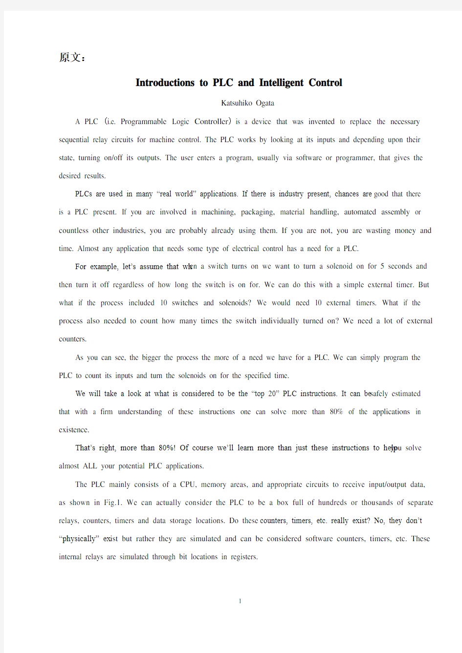
The PLC mainly consists of a CPU, memory areas, and appropriate circuits to receive input/output data, as shown in Fig.1. We can actually consider the PLC to be a box full of hundreds or thousands of separate relays, counters, timers and data storage locations. Do these counters, timers, etc. really exist? No, they don’t “physically” ex ist but rather they are simulated and can be considered software counters, timers, etc. These internal relays are simulated through bit locations in registers.
Fig.1 The structure of PLC
What does each part do?
INPUT RELAYS-(contacts) These are connected to the outside world. They physically exist and receive signals from switches, sensors, etc.. Typically they are not relays but rather they are transistors.
INTERNAL UTILITY RELAYS-(contacts) These do not receive signals from the outside world nor do they physically exist. They are simulated relays and are what enables a PLC to eliminate external relays. There are also some special relays that are dedicated to performing only one task. Some are always on while some are always off. Some are on only once during power-on and are typically used for initializing data that was stored.
COUNTERS-These again do not physically exist. They are simulated counters and they can be programmed to count pulses. Typically these counters can count up, down or both up and down. Since they are simulated, they are limited in their counting speed. Some manufacturers also include high-speed counters that are hardware based. We can think of these as physically existing. Most times these counters can count up, down or up and down.
TIMERS-These also do not physically exist. They come in many varieties and increments.
The most common type is an on-delay type. Others include off-delay and both retentive and non-retentive types. Increments vary from 1ms through 1s.
OUTPUT RELAYS-(coils) These are connected to the outside world. They physically exist and send on/off signals to solenoids, lights, etc.. They can be transistors, relays, or triacs depending upon the model chosen.
DATA STORAGE-Typically there are registers assigned to simply store data. They are usually used as temporary storage for math or data manipulation. They can also typically be used to store data when power is removed from the PLC. Upon power-up they will still have the same contents as before power was removed. Very convenient and necessary!
A PLC works by continually scanning a program. We can think of this scan cycle as consisting of 3 important steps, as shown in Fig.2. There are typically more than 3 but we can focus on the important parts and
not worry about the others. Typically the others are checking the system and updating the current internal counter and timer values.
Fig.2 The work process of PLC
Step 1-CHECK INPUT STATUS-First the PLC takes a look at each input to determine if it is on or off. In other words, is the sensor connected to the first input on? How about the second input? How about the third… It records this data into its memory to be used during the next step.
Step 2-EXECUTE PROGRAM-Next the PLC executes your program one instruction at a time. Maybe your program said that if the first input was on then it should turn on the first output.
Since it already knows which inputs are on/off from the previous step, it will be able to decide whether the first output should be turned on based on the state of the first input. [3] It will store the execution results for use later during the next step.
Step 3-UPDATE OUTPUT STATUS-Finally the PLC updates the status of the outputs. It updates the outputs based on which inputs were on during the first step and the results of executing your program during the second step. Based on the example in step 2 it would now turn on the first output because the first input was on and your program said to turn on the first output when this condition is true.
After the third step the PLC goes back to step one and repeats the steps continuously. One scan time is defined as the time it takes to execute the 3 steps listed above. Thus a practical system is controlled to perform specified operations as desired.
Intelligence and intelligent systems can be characterized in a number of ways and along a number of dimensions. There are certain attributes of intelligent systems, common in many definitions, which are of particular interest to the control community.
In the following, several alternative definitions and certain essential characteristics of intelligent systems are first discussed. A brief working definition of intelligent systems that captures their common characteristics is then presented. In more detail, we start with a rather general definition of intelligent systems, we discuss
levels of intelligence, and we explain the role of control in intelligent systems and outline several alternative definitions. We then discuss adaptation and learning, autonomy and the necessity for efficient computational structures in intelligent systems, to deal with complexity. We conclude with a brief working characterization of intelligent (control) systems.
We start with a general characterization of intelligent systems:
An intelligent system has the ability to act appropriately in an uncertain environment, where an appropriate action is that which increases the probability of success, and success is the achievement of behavioral subgoals that support the system’s ultimate goal.
In order for a man-made intelligent system to act appropriately, it may emulate functions of living creatures and ultimately human mental faculties. An intelligent system can be characterized along a number of dimensions. There are degrees or levels of intelligence that can be measured along the various dimensions of intelligence. At a minimum, intelligence requires the ability to sense the environment, to make decisions and to control action. Higher levels of intelligence may include the ability to recognize objects and events, to represent knowledge in a world model, and to reason about and plan for the future. In advanced forms, intelligence provides the capacity to perceive and understand, to choose wisely, and to act successfully under a large variety of circumstances so as to survive and prosper in a complex and often hostile environment. Intelligence can be observed to grow and evolve, both through growth in computational power and through accumulation of knowledge of how to sense, decide and act in a complex and changing world.
The above characterization of an intelligent system is rather general. According to this, a great number of systems can be considered intelligent. In fact, according to this definition, even a thermostat may be considered to be an intelligent system, although of low level of intelligence. It is common, however, to call a system intelligent when in fact it has a rather high level of intelligence.
There exist a number of alternative but related definitions of intelligent systems and in the following we mention several. They provide alternative, but related characterizations of intelligent systems with emphasis on systems with high degrees of intelligence.
The following definition emphasizes the fact that the system in question processes information, and it focuses on man-made systems and intelligent machines:
A. Machine intelligence is the process of analyzing, organizing and converting data into knowledge; where (machine) knowledge is defined to be the structured information acquired and applied to remove ignorance or uncertainty about a specific task pertaining to the intelligent machine. This definition leads to the
principle of increasing precision with decreasing intelligence, which claims that: applying machine intelligence to a database generates a flow of knowledge, lending an analytic form to facilitate modeling of the process.
Next, an intelligent system is characterized by its ability to dynamically assign subgoals and control actions in an internal or autonomous fashion:
B. Many adaptive or learning control systems can be thought of as designing a control law to meet well-defined control objectives. This activity represents the system’s attempt to organize or order its “knowledge” of its own dynamical behavior, so to meet a control objective. The organization of knowledge can be seen as one important attribute of intelligence. If this organization is done autonomously by the system, then intelligence becomes a property of the system, rather than of the system’s designer. This implies that systems which autonomously(self)
-organize controllers with respect to an internally realized organizational principle are intelligent control systems. [5]
A procedural characterization of intelligent systems is given next:
C. Intelligence is a property of the system that emerges when the procedures of focusing attention, combinatorial search, and generalization are applied to the input information in order to produce the output. One can easily deduce that once a string of the above procedures is defined, the other levels of resolution of the structure of intelligence are growing as a result of the recursion. Having only one level structure leads to a rudimentary intelligence that is implicit in the thermostat, or to a variable-structure sliding mode controller.
The concepts of intelligence and control are closely related and the term “Intelligent Control” has a unique and distinguishable meaning. An intelligent system must define and use goals. Control is then required to move the system to these goals and to define such goals. Consequently, any intelligent system will be a control system. Conversely, intelligence is necessary to provide desirable functioning of systems under changing conditions, and it is necessary to achieve a high degree of autonomous behavior in a control system. Since control is an essential part of any intelligent system, the term “Intelligent Control Systems” is sometimes used in engineering literature instead of “Intelligent Systems” or “Intelligent Machines”. The term “Intelligent Control System” simply stresses the control aspect of the intelligent system.
Below, one more alternative characterization of intelligent (control) systems is included. According to this view, a control system consists of data structures or objects (the plant models and the control goals) and processing units or methods (the control laws) :
D. An intelligent control system is designed so that it can autonomously achieve a high level goal, while
its components, control goals, plant models and control laws are not completely defined, either because they were not known at the design time or because they changed unexpectedly.
There are several essential properties present in different degrees in intelligent systems. One can perceive them as intelligent system characteristics or dimensions along which different degrees or levels of intelligence can be measured. Below we discuss three such characteristics that appear to be rather fundamental in intelligent control systems.
Adaptation and Learning. The ability to adapt to changing conditions is necessary in an intelligent system. Although adaptation does not necessarily require the ability to learn, for systems to be able to adapt to a wide variety of unexpected changes learning is essential. So the ability to learn is an important characteristic of (highly) intelligent systems.
Autonomy and Intelligence. Autonomy in setting and achieving goals is an important characteristic of intelligent control systems. When a system has the ability to act appropriately in an uncertain environment for extended periods of time without external intervention, it is considered to be highly autonomous. There are degrees of autonomy; an adaptive control system can be considered as a system of higher autonomy than a control system with fixed controllers, as it can cope with greater uncertainty than a fixed feedback controller. Although for low autonomy no intelligence (or “low” intelligence) is necessary, for high degrees of autonomy, intelligence in the system (or “high” degrees of intelligence) is essential.
Structures and Hierarchies. In order to cope with complexity, an intelligent system must have an appropriate functional architecture or structure for efficient analysis and evaluation of control strategies. This structure should be “sparse” a nd it should provide a mechanism to build levels of abstraction (resolution, granularity)or at least some form of partial ordering so to reduce complexity. [7] An approach to study intelligent machines involving entropy emphasizes such efficient computational structures. Hierarchies (that may be approximate, localized or combined in heterarchies)that are able to adapt, may serve as primary vehicles for such structures to cope with complexity. The term “hierarchies” refers to functional hierarchies, or hierarchies of range and resolution along spatial or temporal dimensions, and it does not necessarily imply hierarchical hardware. Some of these structures may be hardwired in part. To cope with changing circumstances, the ability to learn is essential, so these structures can adapt to significant, unanticipated changes.
In view of the above, a working characterization of intelligent systems (or of (highly)intelligent (control) systems or machines) that captures the essential characteristics present in any such system is:
An intelligent system must be highly adaptable to significant unanticipated changes, and so learning is essential. It must exhibit high degree of autonomy in dealing with changes. It must be able to deal with significant complexity, and this leads to certain sparse types of functional architectures such as hierarchies.
Nationality:USA
Source:Modern Control Engineering .Prentice Hall
译文:
PLC和智能控制简介
尾形克彦
PLC(即可编程逻辑控制器)是机械控制中为替代必要的继电器时序电路而发明的一种设备。PLC工作时通过查询输入端并根据其状态打开或关闭输出。用户通常用软件或编程器输入程序,从而获得期望的结果。
很多实际应用都采用PLC。工业生产中应用PLC的可能性很高。如果你正在进行机械制造、产品包装、材料处理、自动化装配及无数其他工业生产,你可能已经用到了PLC。如果没有用到,那就是在浪费金钱和时间。几乎所有需要电气控制的地方都需要PLC。
例如,假定在开关闭合时我们需要一个线圈接通5秒,然后不管开关接通多长时间都将线圈断开。我们可以通过一个简单的外部定时器来实现。但是假如该过程有十个开关和线圈呢?我们就需要十个外部定时器。如果这个过程需要分别记录每个开关开启的次数呢?我们又需要很多外部计数器。
由此可见,系统越大,我们就越需要PLC。我们可以简单地用PLC编程来对输入信号进行计数,并在规定的时间接通线圈。
我们考察一下哪些是PLC中最常用的20条指令。保守地估计一下,如果真正地掌握了这些指令,就能解决80%以上现存的应用问题。
是的,80%以上!当然,我们要学习的指令比这些更多,以帮助你解决几乎所有潜在的PLC应用问题。
PLC 主要由中央处理器(CPU)、存储器和输入、输出电路构成,如图1所示。我们可以将PLC看成是一个装满了成百上千个独立的继电器、计数器、定时器以及数据存储器的盒子。这些计数器、定时器等是不是真的存在呢?不,它们都是模拟的,物理上并不存在,但可以将它们看成是软计数器、软定时器等。这些内部继电器是用寄存器中的位单元模拟出来的。
输入电路中央处理器存储器输出电路
输入继电器
内部通用继电器
计数器
计时器
输出继电器
数据存储器
图1 PLC的结构
各个部分是如何工作的呢?
输入继电器(触点)这些继电器连接外部电路。它们是实际存在的,并接收来自开关、传感器等的信号,通常是晶体管而非继电器。
内部通用继电器(触点)它们不从外部设备接收信号,也非物理上存在的。它们是模拟的继电器,用以消除PLC的外部继电器。此外还有一些特殊继电器,专门执行一项任务。其中一些是常开的,一些是常闭的。有一些仅在电源上电时导通一次,通常用来初始化存储的数据。
计数器它们也非物理上存在的,而是模拟的计数器,可通过编程来对脉冲进行计数。通常它们可进行加计数、减计数或同时进行加减计数。因为它们是用软件模拟的,计数速度就有限。一些制造商提供了基于硬件的高速计数器。这样的计数器可以认为是物理上存在的。这些计数器多数情况下可以进行加计数、减计数或同时进行加减计数。
定时器它们也非物理上存在的,分为多种类型和定时单位。最常用的一种类型是延时导通型。其他类型还有延时断开型、记忆和非记忆型。定时单位的范围是1ms 到1s。
输出继电器(线圈)该部分连接到外围电路。它们是物理上存在的,并给线圈、灯等发送开关信号。输出继电器可以是晶体管、继电器或可控硅,取决于选择的型号。
数据存储器它们通常是用来存储数据的寄存器,一般作为运算或数据处理的暂存器。在PLC断电时通常还可用来存储数据。再次接通电源后,其内容与断电前相同,非常方便且必要。
PLC是通过连续扫描一个程序来工作的。我们可以认为扫描周期是由3个主要阶段组成的,如图2所示。当然有多于三个阶段的情况,但我们可关注重要的环节,忽略其他环节。其他阶段通常正在检查系统及更新内部计数器和定时器的当前值。
检查输入状态
执行程序
更新输出状态
图2 PLC的工作过程
第一步——检查输入状态——首先PLC检查每一个输入是否接通。换句话说就是,与
冲压模具技术外文翻译(含外文文献)
前言 在目前激烈的市场竞争中,产品投入市场的迟早往往是成败的关键。模具是高质量、高效率的产品生产工具,模具开发周期占整个产品开发周期的主要部分。因此客户对模具开发周期要求越来越短,不少客户把模具的交货期放在第一位置,然后才是质量和价格。因此,如何在保证质量、控制成本的前提下加工模具是值得认真考虑的问题。模具加工工艺是一项先进的制造工艺,已成为重要发展方向,在航空航天、汽车、机械等各行业得到越来越广泛的应用。模具加工技术,可以提高制造业的综合效益和竞争力。研究和建立模具工艺数据库,为生产企业提供迫切需要的高速切削加工数据,对推广高速切削加工技术具有非常重要的意义。本文的主要目标就是构建一个冲压模具工艺过程,将模具制造企业在实际生产中结合刀具、工件、机床与企业自身的实际情况积累得高速切削加工实例、工艺参数和经验等数据有选择地存储到高速切削数据库中,不但可以节省大量的人力、物力、财力,而且可以指导高速加工生产实践,达到提高加工效率,降低刀具费用,获得更高的经济效益。 1.冲压的概念、特点及应用 冲压是利用安装在冲压设备(主要是压力机)上的模具对材料施加压力,使其产生分离或塑性变形,从而获得所需零件(俗称冲压或冲压件)的一种压力加工方法。冲压通常是在常温下对材料进行冷变形加工,且主要采用板料来加工成所需零件,所以也叫冷冲压或板料冲压。冲压是材料压力加工或塑性加工的主要方法之一,隶属于材料成型工程术。 冲压所使用的模具称为冲压模具,简称冲模。冲模是将材料(金属或非金属)批量加工成所需冲件的专用工具。冲模在冲压中至关重要,没有符合要求的冲模,批量冲压生产就难以进行;没有先进的冲模,先进的冲压工艺就无法实现。冲压工艺与模具、冲压设备和冲压材料构成冲压加工的三要素,只有它们相互结合才能得出冲压件。 与机械加工及塑性加工的其它方法相比,冲压加工无论在技术方面还是经济方面都具有许多独特的优点,主要表现如下; (1) 冲压加工的生产效率高,且操作方便,易于实现机械化与自动化。这是
控制系统基础论文中英文资料外文翻译文献
控制系统基础论文中英文资料外文翻译文献 文献翻译 原文: Numerical Control One of the most fundamental concepts in the area of advanced manufacturing technologies is numerical control (NC).Prior to the advent of NC, all machine tools were manual operated and controlled. Among the many limitations associated with manual control machine tools, perhaps none is more prominent than the limitation of operator skills. With manual control, the quality of the product is directly related to and limited to the skills of the operator . Numerical control represents the first major step away from human control of machine tools. Numerical control means the control of machine tools and other manufacturing systems though the use of prerecorded, written symbolic instructions. Rather than operating a machine tool, an NC technician writes a program that issues operational instructions to the machine tool, For a machine tool to be numerically controlled , it must be interfaced with a device for accepting and decoding the p2ogrammed instructions, known as a reader. Numerical control was developed to overcome the limitation of human operator , and it has done so . Numerical control machines are more accurate than manually operated machines , they can produce parts more uniformly , they are faster, and the long-run tooling costs are lower . The development of NC led to the development of several other innovations in manufacturing technology: 1.Electrical discharge machining. https://www.360docs.net/doc/ec8369386.html,ser cutting. 3.Electron beam welding.
电气工程及其自动化专业光伏单相逆变器并网控制技术研究 开题报告 文献综述 外文翻译
摘要 随着“绿色环保”概念的提出,以解决电力紧张,环境污染等问题为目的的新能源利用方案得到了迅速的推广,这使得研究可再生能源回馈电网技术具有了十分重要的现实意义。如何可靠地、高质量地向电网输送功率是一个重要的问题,因此在可再生能源并网发电系统中起电能变换作用的逆变器成为了研究的一个热点。 本文以全桥逆变器为对象,详细论述了基于双电流环控制的逆变器并网系统的工作原理,推导了控制方程。内环通过控制LCL滤波中的电容电流,外环控制滤波后的网侧电流。大功率并网逆变器的开关频率相对较低,相对于传统的L 型或LC 型滤波器,并网逆变器采用LCL 型输出滤波器具有输出电流谐波小,滤波器体积小的优点,在此基础上本系统设计了LCL滤波器。本文分析比较了单相逆变器并网采用单闭环和双闭环两种控制策略下的并网电流,并对突加扰动情况下系统动态变化进行了分析。 在完成并网控制系统理论分析的基础上,本文设计并制作了基于TMS320LF2407DSP的数字化控制硬件实验系统,包括DSP 外围电路、模拟量采样及调理电路、隔离驱动电路、保护电路和辅助电源等,最后通过MATLAB仿真软件进行验证理论的可行性,实现功率因数为1的并网要求。 关键词并网逆变器;LCL滤波器;双电流环控制;DSP
Abstract With the concept of”Green and Environmental Protection”was proposed.All kinds of new energy exploitation program are in the rapid promotion,which is in order to solve the power shortage,pollution and other issues.It makes exploring renewable energy feedback the grid technology has a very important practical significance.How to deliver power into the grid reliably and quality is an important problem,the inverter mat Can transform the electrical energy in the system of the renewable resource to be fed into the grid is becoming one of the hot points in intemational research. Based on the bridge inverter the analysis of the working principle and the deduction of the control equation have been presented. The strategy integrates an outer loop grid current regulator with capacitor current regulation to stabilize the system. The current regulation is used for the outer grid current control loop. The frequency of switching is slower in the high power grid-connected inverter. Compared with tradition type L or type LC, output filter and output current’s THD of type LCL are all smaller.So on this basis, the system uses the LCL filter. This paper compares the net current of the single-phase inverter and net single loop and double loop under two control strategies, and the case of sudden disturbance of the dynamic change of the system. In complete control system on the basis of theoretical analysis, design and production of this article is based on TMS320LF2407DSP’s digital control hardware test system, including the DSP external circuit, analog sampling and conditioning circuit, isolation, driver circuit, protection circuit and auxiliary power, etc., via MATLAB software to validate the feasibility of the theory.Achieve power factor is 1 and network requirements. Keywords Grid-connected inverter;LCL filter; Double current loop control; DSP
(完整版)建筑外文翻译毕业设计论文
随着我国经济的发展,建筑行业已经朝着多元化方向发展,建筑行业在我国经济发展中起着非常重要的作用。而建筑工程管理工作直接关系到工程的质量、成本管理、人员的安全、企业的经营效益,甚至关系到企业的生死存亡,但是我国建筑工程管理在现阶段存在许多的不足:管理体制不健全。我国大部分的建筑工程为了节约人员开支,减少了建筑工程管理机构的人员数量和质量。管理制度深入性不足。建筑行业的相关管理制度都是由一些著名的建筑行业专家等共同研究制定的,但是在各建筑单位中就只是一张纸,他们也都只是为了应付上级的检查,并不能应用到建筑工程管理上。 在我国建筑工程管理工作中,难以全面确立我国建筑工程管理思路体系,主要是因为我国缺乏管理理论和经验。建立建筑工程管理思路体系是专业性较强的问题,其实施必须由资深的建筑学科专家和具有丰富工作经验的管理人员来组织,只有这样才能实现。国外建筑行业无论是技术还是理论都比较先进,因此我国在建筑工程管理思路体系的建立过程中,必须借鉴国外的先进理念,另外,还必须吸取先进的建筑工程管理方法,并对各方面的资料加以综合和整体。总之,要想确保我国建筑工程管理工作的有序进行,必须以健全的工程管理思路体系作为建筑工程总体管理水平提升的基本保障。加强施工质量管理,建立合理可行的质量保证体系,将工程的质量工作落到实处。工程施工企业要根据质量保证体系,形成行之有效的质量保证系统,树立质量方针,从而让其更加有指令性、系统性及可操作
性。要将人、材料和机械各个要素有效结合起来。 首先,人是质量控制的核心,要把人作为控制的推动力,充分调动人的积极性,树立工程质量第一的观念。其次,施工材料作为建筑产品的主体,对材料质量的控制是工程质量控制的关键。最后,工程施工的机械是进行施工机械化的主要标志,对现代化项目施工起到不可缺少的作用,它直接影响了施工项目的进度和质量,所以,选好用好工程机械设备非常重要。所以,应该根据工程项目的具体特点,综合考虑各种环境因素,实施有效的施工现场控制,为保证施工质量及安全创造良好的外部条件。 现阶段建筑工程管理越来越受到人们的重视,项目成本管理是工程管理不可或缺的内容。工程管理本质特征可以由项目成本管理体现出来。首先,建立项目成本管理责任制。项目管理人员的成本责任,不同于工作责任,工作责任完成不等于成本责任完成。在完成工作责任的同时,还应考虑成本责任的实施,进一步明确成本管理责任,使每个管理者都有成本管理意识,做到精打细算。其次,对施工队实行分包成本控制。项目部与施工队之间建立特定劳务合同关系,项目部有权对施工队的进度、质量、安全和现场管理标准进行监督管理,同时按合同支付劳务费用。再次,施工队成本的控制,由施工队自身管理,项目部不应该过多干预。 为了保证政府监督工作的有效性和权威性,应该提高监督队伍的整体素质。因此,加强建筑工程质量监督机构的质量管理的学习,从而使得监督队伍的业务素质得以提高。另外,质量监督手段也要不断进行完善,增加检测设备,使得监督工作具有较大科技的含量,实现监督工作的现代化。从建设市场的整体来看,市场运行的规则不够完善。执法不严,违法不究的现象常常会出现。工程质量受到危害在很大程度上都是由于建设市场的混乱所造成的。因此,政府必须建立健全的运行规则,保证这些规则能够真正落实处。
机械设计外文翻译(中英文)
机械设计理论 机械设计是一门通过设计新产品或者改进老产品来满足人类需求的应用技术科学。它涉及工程技术的各个领域,主要研究产品的尺寸、形状和详细结构的基本构思,还要研究产品在制造、销售和使用等方面的问题。 进行各种机械设计工作的人员通常被称为设计人员或者机械设计工程师。机械设计是一项创造性的工作。设计工程师不仅在工作上要有创造性,还必须在机械制图、运动学、工程材料、材料力学和机械制造工艺学等方面具有深厚的基础知识。如前所诉,机械设计的目的是生产能够满足人类需求的产品。发明、发现和科技知识本身并不一定能给人类带来好处,只有当它们被应用在产品上才能产生效益。因而,应该认识到在一个特定的产品进行设计之前,必须先确定人们是否需要这种产品。 应当把机械设计看成是机械设计人员运用创造性的才能进行产品设计、系统分析和制定产品的制造工艺学的一个良机。掌握工程基础知识要比熟记一些数据和公式更为重要。仅仅使用数据和公式是不足以在一个好的设计中做出所需的全部决定的。另一方面,应该认真精确的进行所有运算。例如,即使将一个小数点的位置放错,也会使正确的设计变成错误的。 一个好的设计人员应该勇于提出新的想法,而且愿意承担一定的风险,当新的方法不适用时,就使用原来的方法。因此,设计人员必须要有耐心,因为所花费的时间和努力并不能保证带来成功。一个全新的设计,要求屏弃许多陈旧的,为人们所熟知的方法。由于许多人墨守成规,这样做并不是一件容易的事。一位机械设计师应该不断地探索改进现有的产品的方法,在此过程中应该认真选择原有的、经过验证的设计原理,将其与未经过验证的新观念结合起来。 新设计本身会有许多缺陷和未能预料的问题发生,只有当这些缺陷和问题被解决之后,才能体现出新产品的优越性。因此,一个性能优越的产品诞生的同时,也伴随着较高的风险。应该强调的是,如果设计本身不要求采用全新的方法,就没有必要仅仅为了变革的目的而采用新方法。 在设计的初始阶段,应该允许设计人员充分发挥创造性,不受各种约束。即使产生了许多不切实际的想法,也会在设计的早期,即绘制图纸之前被改正掉。只有这样,才不致于堵塞创新的思路。通常,要提出几套设计方案,然后加以比较。很有可能在最后选定的方案中,采用了某些未被接受的方案中的一些想法。
基于单片机的步进电机控制系统设计外文翻译
毕业设计(论文)外文资料翻译 学院:机械工程学院 专业:机械设计制造及其自动化 姓名: 学号:XXXXXXXXXX 外文出处:《Computational Intelligence and (用外文写)Design》 附件: 1.外文资料翻译译文;2.外文原文。 注:请将该封面与附件装订成册。
附件1:外文资料翻译译文 基于微型计算机的步进电机控制系统设计 孟天星余兰兰 山东理工大学电子与电气工程学院 山东省淄博市 摘要 本文详细地介绍了一种以AT89C51为核心的步进电机控制系统。该系统设计包括硬件设计、软件设计和电路设计。电路设计模块包括键盘输入模块、LED显示模块、发光二极管状态显示和报警模块。按键可以输入设定步进电机的启停、转速、转向,改变转速、转向等的状态参数。通过键盘输入的状态参数来控制步进电机的步进位置和步进速度进而驱动负载执行预订的工作。运用显示电路来显示步进电机的输入数据和运行状态。AT89C51单片机通过指令系统和编译程序来执行软件部分。通过反馈检测模块,该系统可以很好地完成上述功能。 关键词:步进电机,AT89C51单片机,驱动器,速度控制 1概述 步进电机因为具有较高的精度而被广泛地应用于运动控制系统,例如机器人、打印机、软盘驱动机、绘图仪、机械式阀体等等。过去传统的步进电机控制电路和驱动电路设计方法通常都极为复杂,由成本很高而且实用性很差的电器元件组成。结合微型计算机技术和软件编程技术的设计方法成功地避免了设计大量复杂的电路,降低了使用元件的成本,使步进电机的应用更广泛更灵活。本文步进电机控制系统是基于AT89C51单片机进行设计的,它具有电路简单、结构紧凑的特点,能进行加减速,转向和角度控制。它仅仅需要修改控制程序就可以对各种不同型号的步进电机进行控制而不需要改变硬件电路,所以它具有很广泛的应用领域。 2设计方案 该系统以AT89C51单片机为核心来控制步进电机。电路设计包括键盘输入电路、LED显示电路、发光二极管显示电路和报警电路,系统原理框图如图1所示。 At89c51单片机的P2口输出控制步进电机速度的时钟脉冲信号和控制步进电机运转方向的高低电平。通过定时程序和延时程序可以控制步进电机的速度和在某一
光伏电站 毕业设计 开题报告
毕业设计(论文)开题报告 题目新疆哈密东南山口 50Mwp光伏电站设计 专业电力 班级 学生 指导教师 2015 年
一、毕业设计(论文)课题来源、类型 课题来源:由于本人家乡新疆哈密地区光照条件十分优越,故拟在哈密东南山口地区建一个容量为50Mwp的并网光伏电站,经在网上查阅相应的资料后,已搜到相关设计标准和设计流程,可以作为一个研究课题。 类型:理论研究 二、选题的目的及意义 2.1太阳能的优势 太阳能作为一种新型的绿色可再生能源,与其他新能源相比利用最大,是最理想的可再生能源。因为它具有以下的特点: (1)数量巨大:每年到达地球表面能供人类利用的太阳辐射相当于一颗原子弹爆炸时所发出的能量; (2)时间长久:用之不竭,太阳按目前功率辐射能量其时间约可持续100亿年; (3)普照大地:取之不尽,不需要开采和运输; (4)清洁无污染:无任何物质的排放,既不会留下污染物,也不会向大气中排放废气。 2.2光伏发电的优势 太阳能的开发利用主要有光热利用、光伏利用、光化学利用等三种形式。目前,以太阳能电池技术为核心的太阳能光伏利用成为太阳能开发利用中最重要的应用领域,因为光伏发电具有以下明显优点:
(1)结构简单,体积小且轻。能独立供电的太阳能电池组件和方阵结构都比较简单,输出50W的晶体硅太阳能电池组件,体积约为450mm×985mm×45mm,质量为7kg。 (2)容易安装运输,建设周期短。只要将太阳能电池支撑并面向太阳即可发电,宜于制成小功率移动电源; (3)维护简单,使用方便。如遇风雨天,只需检查太阳电池表面是否被粘污、接线是否可靠、蓄电池电压是否正常即可。大型光伏电站使用计算机控制运行,运行费用很低。 (4)清洁、安全、无噪声。光伏发电本身不向外界排放废物,没有机械噪声,是一种理想的能源。 (5)可靠性高,寿命长,并且应用范围广。晶体硅太阳能电池的寿命可以长达20至35年,在光伏系统中,只要设计合理、选型适当,蓄电池的寿命可以达到10多年;太阳能几乎无处不在,太阳能电池在中国大部分范围内都能作为独立的电源。 2.3阳能开发潜力 在中国,太阳能资源较好的地区占国土面积2/3以上,主要集中在西部地区,尤其是西北和青藏高原,年平均日照在2200小时以上,中国陆地每年接收的太阳辐射量约合24000亿吨标准煤。太阳能发电虽受昼夜、晴雨、季节的影响,但可以分散的进行,所以它适于各家各户分别进行发电,而且可以连接到供电网络上,使得各个家庭在电力富裕时可将其卖给电力公司,不足时又可以从电力公司买入。分布式光伏发电并网系统将可能是今后住宅和办公用电的主要模式。太阳能发电有更加激动人心的计划。一
毕业设计外文翻译附原文
外文翻译 专业机械设计制造及其自动化学生姓名刘链柱 班级机制111 学号1110101102 指导教师葛友华
外文资料名称: Design and performance evaluation of vacuum cleaners using cyclone technology 外文资料出处:Korean J. Chem. Eng., 23(6), (用外文写) 925-930 (2006) 附件: 1.外文资料翻译译文 2.外文原文
应用旋风技术真空吸尘器的设计和性能介绍 吉尔泰金,洪城铱昌,宰瑾李, 刘链柱译 摘要:旋风型分离器技术用于真空吸尘器 - 轴向进流旋风和切向进气道流旋风有效地收集粉尘和降低压力降已被实验研究。优化设计等因素作为集尘效率,压降,并切成尺寸被粒度对应于分级收集的50%的效率进行了研究。颗粒切成大小降低入口面积,体直径,减小涡取景器直径的旋风。切向入口的双流量气旋具有良好的性能考虑的350毫米汞柱的低压降和为1.5μm的质量中位直径在1米3的流量的截止尺寸。一使用切向入口的双流量旋风吸尘器示出了势是一种有效的方法,用于收集在家庭中产生的粉尘。 摘要及关键词:吸尘器; 粉尘; 旋风分离器 引言 我们这个时代的很大一部分都花在了房子,工作场所,或其他建筑,因此,室内空间应该是既舒适情绪和卫生。但室内空气中含有超过室外空气因气密性的二次污染物,毒物,食品气味。这是通过使用产生在建筑中的新材料和设备。真空吸尘器为代表的家电去除有害物质从地板到地毯所用的商用真空吸尘器房子由纸过滤,预过滤器和排气过滤器通过洁净的空气排放到大气中。虽然真空吸尘器是方便在使用中,吸入压力下降说唱空转成比例地清洗的时间,以及纸过滤器也应定期更换,由于压力下降,气味和细菌通过纸过滤器内的残留粉尘。 图1示出了大气气溶胶的粒度分布通常是双峰形,在粗颗粒(>2.0微米)模式为主要的外部来源,如风吹尘,海盐喷雾,火山,从工厂直接排放和车辆废气排放,以及那些在细颗粒模式包括燃烧或光化学反应。表1显示模式,典型的大气航空的直径和质量浓度溶胶被许多研究者测量。精细模式在0.18?0.36 在5.7到25微米尺寸范围微米尺寸范围。质量浓度为2?205微克,可直接在大气气溶胶和 3.85至36.3μg/m3柴油气溶胶。
机械类外文翻译
机械类外文翻译 塑料注塑模具浇口优化 摘要:用单注塑模具浇口位置的优化方法,本文论述。该闸门优化设计的目的是最大限度地减少注塑件翘曲变形,翘曲,是因为对大多数注塑成型质量问题的关键,而这是受了很大的部分浇口位置。特征翘曲定义为最大位移的功能表面到表面的特征描述零件翘曲预测长度比。结合的优化与数值模拟技术,以找出最佳浇口位置,其中模拟armealing算法用于搜索最优。最后,通过实例讨论的文件,它可以得出结论,该方法是有效的。 注塑模具、浇口位臵、优化、特征翘曲变形关键词: 简介 塑料注射成型是一种广泛使用的,但非常复杂的生产的塑料产品,尤其是具有高生产的要求,严密性,以及大量的各种复杂形状的有效方法。质量ofinjection 成型零件是塑料材料,零件几何形状,模具结构和工艺条件的函数。注塑模具的一个最重要的部分主要是以下三个组件集:蛀牙,盖茨和亚军,和冷却系统。拉米夫定、Seow(2000)、金和拉米夫定(2002) 通过改变部分的尼斯达到平衡的腔壁厚度。在平衡型腔充填过程提供了一种均匀分布压力和透射电镜,可以极大地减少高温的翘曲变形的部分~但仅仅是腔平衡的一个重要影响因素的一部分。cially Espe,部分有其功能上的要求,其厚度通常不应该变化。 pointview注塑模具设计的重点是一门的大小和位臵,以及流道系统的大小和布局。大门的大小和转轮布局通常被认定为常量。相对而言,浇口位臵与水口大小布局也更加灵活,可以根据不同的零件的质量。 李和吉姆(姚开屏,1996a)称利用优化流道和尺寸来平衡多流道系统为multiple 注射系统。转轮平衡被形容为入口压力的差异为一多型腔模具用相同的蛀牙,也存
速度控制系统设计外文翻译
译文 流体传动及控制技术已经成为工业自动化的重要技术,是机电一体化技术的核心组成之一。而电液比例控制是该门技术中最具生命力的一个分支。比例元件对介质清洁度要求不高,价廉,所提供的静、动态响应能够满足大部分工业领域的使用要求,在某些方面已经毫不逊色于伺服阀。比例控制技术具有广阔的工业应用前景。但目前在实际工程应用中使用电液比例阀构建闭环控制系统的还不多,其设计理论不够完善,有待进一步的探索,因此,对这种比例闭环控制系统的研究有重要的理论价值和实践意义。本论文以铜电解自动生产线中的主要设备——铣耳机作为研究对象,在分析铣耳机组各构成部件的基础上,首先重点分析了铣耳机的关键零件——铣刀的几何参数、结构及切削性能,并进行了实验。用电液比例方向节流阀、减压阀、直流直线测速传感器等元件设计了电液比例闭环速度控制系统,对铣耳机纵向进给装置的速度进行控制。论文对多个液压阀的复合作用作了理论上的深入分析,着重建立了带压差补偿型的电液比例闭环速度控制系统的数学模型,利用计算机工程软件,研究分析了系统及各个组成环节的静、动态性能,设计了合理的校正器,使设计系统性能更好地满足实际生产需要 水池拖车是做船舶性能试验的基本设备,其作用是拖曳船模或其他模型在试验水池中作匀速运动,以测量速度稳定后的船舶性能相关参数,达到预报和验证船型设计优劣的目的。由于拖车稳速精度直接影响到模型运动速度和试验结果的精度,因而必须配有高精度和抗扰性能良好的车速控制系统,以保证拖车运动的稳速精度。本文完成了对试验水池拖车全数字直流调速控制系统的设计和实现。本文对试验水池拖车工作原理进行了详细的介绍和分析,结合该控制系统性能指标要求,确定采用四台直流电机作为四台车轮的驱动电机。设计了电流环、转速环双闭环的直流调速控制方案,并且采用转矩主从控制模式有效的解决了拖车上四台直流驱动电机理论上的速度同步和负载平衡等问题。由于拖车要经常在轨道上做反复运动,拖动系统必须要采用可逆调速系统,论文中重点研究了逻辑无环流可逆调速系统。大型直流电机调速系统一般采用晶闸管整流技术来实现,本文给出了晶闸管整流装置和直流电机的数学模型,根据此模型分别完成了电流坏和转速环的设计和分析验证。针对该系统中的非线性、时变性和外界扰动等因素,本文将模糊控制和PI控制相结合,设计了模糊自整定PI控制器,并给出了模糊控制的查询表。本文在系统基本构成及工程实现中,介绍了西门子公司生产的SIMOREGDC Master 6RA70全数字直流调速装置,并设计了该调速装置的启动操作步骤及参数设置。完成了该系统的远程监控功能设计,大大方便和简化了对试验水池拖车的控制。对全数字直流调速控制系统进行了EMC设计,提高了系统的抗干扰能力。本文最后通过数字仿真得到了该系统在常规PI控制器和模糊自整定PI控制器下的控制效果,并给出了系统在现场调试运行时的试验结果波形。经过一段时间的试运行工作证明该系统工作良好,达到了预期的设计目的。 提升装置在工业中应用极为普遍,其动力机构多采用电液比例阀或电液伺服阀控制液压马达或液压缸,以阀控马达或阀控缸来实现上升、下降以及速度控制。电液比例控制和电液伺服控制投资成本较高,维护要求高,且提升过程中存在速度误差及抖动现象,影响了正常生产。为满足生产要求,提高生产效率,需要研究一种新的控制方法来解决这些不足。随着科学技术的飞速发展,计算机技术在液压领域中的应用促进了电液数字控制技术的产生和发展,也使液压元件的数字化成为液压技术发展的必然趋势。本文以铅电解残阳极洗涤生产线中的提升装置为研究
太阳能光伏系统蓄电池充电中英文对照外文翻译文献
(文档含英文原文和中文翻译) 中英文对照外文翻译 Design of a Lead-Acid Battery Charging and Protecting IC in Photovoltaic System 1.Introduction Solar energy as an inexhaustible, inexhaustible source of energy more and more attention. Solar power has become popular in many countries and regions, solar lighting has also been put into use in many cities in China. As a key part of the solar lighting, battery charging and protection is particularly important. Sealed maintenance-free lead-acid battery has a sealed, leak-free, pollution-free, maintenance-free, low-cost, reliable power supply during the entire life of the battery voltage is stable and no maintenance, the need for uninterrupted for the various types
of has wide application in power electronic equipment, and portable instrumentation. Appropriate float voltage, in normal use (to prevent over-discharge, overcharge, over-current), maintenance-free lead-acid battery float life of up to 12 ~ 16 years float voltage deviation of 5% shorten the life of 1/2. Thus, the charge has a major impact on this type of battery life. Photovoltaic, battery does not need regular maintenance, the correct charge and reasonable protection, can effectively extend battery life. Charging and protection IC is the separation of the occupied area and the peripheral circuit complexity. Currently, the market has not yet real, charged with the protection function is integrated on a single chip. For this problem, design a set of battery charging and protection functions in one IC is very necessary. 2.System design and considerations The system mainly includes two parts: the battery charger module and the protection module. Of great significance for the battery as standby power use of the occasion, It can ensure that the external power supply to the battery-powered, but also in the battery overcharge, over-current and an external power supply is disconnected the battery is to put the state to provide protection, the charge and protection rolled into one to make the circuit to simplify and reduce valuable product waste of resources. Figure 1 is a specific application of this Ic in the photovoltaic power generation system, but also the source of this design. Figure1 Photovoltaic circuit system block diagram Maintenance-free lead-acid battery life is usually the cycle life and float life factors affecting the life of the battery charge rate, discharge rate, and float voltage. Some manufacturers said that if the overcharge protection circuit, the charging rate can be achieved even more than 2C (C is the rated capacity of the battery), battery manufacturers recommend charging rate of C/20 ~ C/3. Battery voltage and temperature, the temperature is increased by 1 °C, single cell battery voltage drops 4 mV , negative temperature coefficient of -4 mV / ° C means that the battery float voltage. Ordinary charger for the best working condition at 25 °C; charge less than the ambient temperature of 0 °C; at 45 °C may shorten the battery life due to severe overcharge. To make the battery to extend the working life, have a certain solar battery array Charge controller controller Discharge controller DC load accumulator
土木工程毕业设计范文,图纸计算书、建筑说明书外文翻译、开题报告书
- - -. 毕业设计(论文) 开题报告 题目XX雅筑地产中天锦庭6号住宅楼设计 专业土木工程 班级 学生 指导教师教授 讲师
一、毕业设计(论文)课题来源、类型 本论文课题来源于XX雅筑地产中天锦庭6号住宅楼设计,本设计来自工程实际,结构类型为钢筋混凝土剪力墙结构。该建筑分十三层,耐火等级为一级,主体结构为二级耐久年限,抗震设防为八级。二、选题的目的及意义 随着我国经济发展和城市化进程,人们对住宅的需求量逐渐增多,住宅物业管理日益为人们所关注。住宅小区已经成为人们安家置业的首选,几十万到几百万的小区住宅比比皆是。尤其近几年,高层小高层已然成为现代开发商与消费者选择的主流。这是由高层和小高层的特点所决定的,高层建筑可节约城市用地,缩短公用设施和市政管网的开发周期。人们花的钱越多,不但对住宅的本身的美观质量要求越来越高,同时对物业小区的服务和管理也要求越来越高,比如对小区的绿化,保安,停车场,维修甚至对各项投诉的要求小区管理者做的好。信息时代的今天,住宅小区的硬件设施也必须跟得上时代的步伐,对现代化住宅小区建设的要求越来越高。小区楼的艺术美更要符合现代人的需求,此外还必须有较高的实用性、经济性。住宅小区的居住环境安全与否,是小区居民极其关心的问题,要创建一个安全的居住环境不仅要有科学的小区管理制度,而且在很大程度上也依赖于小区规划的安全性,这其中涉及到居民的生理、心理安全和社会安全等因素。在住宅小区的规划设计中应充分考虑居民的有效防X行为,通过控制小区和组团入口、明确划分空间领域等措施来提高小区的安全防卫能力。一是在小区和组团的入口处设置明显标志,使住宅小区具有较强的领域性和归属性。二是注重院落空间的强化,使居民之间既有充分了解和相互熟悉的机会,又可以使住户视线能够触及到住宅入口,便于对陌生人进行观察、监视。三是注重小区交通网络的合理组织。在小区主干道的规划设计上要做到“顺而不穿,通而不畅”,减少交通环境的混乱交杂,提高安全系数,在小区级道路的规划上尽量作曲形设计,限制车辆穿行的速度,达到安全与降低噪音的目的。同时,规划时应尽量减少组团的出入口,一般设置两个即可,以便有效控制外来行人任意穿行,从而起到安全防卫的作用。我这次选择的是高层住宅楼的设计,目的就是为了设计一栋满足居住需求和美观要求的住宅楼。并且也可以通过这次的毕业设计,把以前学习的专业课的知识运用到实践中,以及对它们更加深入的学习和系统化的总结。在这个过程中需要查阅、搜集许多的资料,将提高我运用图书馆的资料文献和互联网上大量信息的能力。office办公软件的综合运用使我的电脑基本功有了很大的提高。从建筑设计到结构的计算设计都是由自己单独完成,这就培养了我们独立解决设计中的问题以及娴熟使用auto CAD和PKPM系列软件的能力。综合性地运用几年内所学知识去分析、解决一个问题,在作毕业设计的过程中,所学知识得到疏理和运用,它既是一次检阅,又是一次锻炼。
机械图纸中英文翻译汇总
近几年,我厂和英国、西班牙的几个公司有业务往来,外商传真发来的图纸都是英文标注,平时阅看有一定的困难。下面把我们积累的几点看英文图纸的经验与同行们交流。 1标题栏 英文工程图纸的右下边是标题栏(相当于我们的标题栏和部分技术要求),其中有图纸名称(TILE)、设计者(DRAWN)、审查者(CHECKED)、材料(MATERIAL)、日期(DATE)、比例(SCALE)、热处理(HEAT TREATMENT)和其它一些要求,如: 1)TOLERANCES UNLESS OTHERWISE SPECIFIAL 未注公差。 2)DIMS IN mm UNLESS STATED 如不做特殊要求以毫米为单位。 3)ANGULAR TOLERANCE±1°角度公差±1°。 4)DIMS TOLERANCE±0.1未注尺寸公差±0.1。 5)SURFACE FINISH 3.2 UNLESS STATED未注粗糙度3.2。 2常见尺寸的标注及要求 2.1孔(HOLE)如: (1)毛坯孔:3"DIAO+1CORE 芯子3"0+1; (2)加工孔:1"DIA1"; (3)锪孔:锪孔(注C'BORE=COUNTER BORE锪底面孔); (4)铰孔:1"/4 DIA REAM铰孔1"/4; (5)螺纹孔的标注一般要表示出螺纹的直径,每英寸牙数(螺矩)、螺纹种类、精度等级、钻深、攻深,方向等。如: 例1.6 HOLES EQUI-SPACED ON 5"DIA (6孔均布在5圆周上(EQUI-SPACED=EQUALLY SPACED均布) DRILL 1"DIATHRO' 钻1"通孔(THRO'=THROUGH通) C/SINK22×6DEEP 沉孔22×6 例2.TAP7"/8-14UNF-3BTHRO' 攻统一标准细牙螺纹,每英寸14牙,精度等级3B级 (注UNF=UNIFIED FINE THREAD美国标准细牙螺纹) 1"DRILL 1"/4-20 UNC-3 THD7"/8 DEEP 4HOLES NOT BREAK THRO钻 1"孔,攻1"/4美国粗牙螺纹,每英寸20牙,攻深7"/8,4孔不准钻通(UNC=UCIFIED COARSE THREAD 美国标准粗牙螺纹)
毕业设计外文翻译---控制系统介绍
英文原文 Introductions to Control Systems Automatic control has played a vital role in the advancement of engineering and science. In addition to its extreme importance in space-vehicle, missile-guidance, and aircraft-piloting systems, etc, automatic control has become an important and integral part of modern manufacturing and industrial processes. For example, automatic control is essential in such industrial operations as controlling pressure, temperature, humidity, viscosity, and flow in the process industries; tooling, handling, and assembling mechanical parts in the manufacturing industries, among many others. Since advances in the theory and practice of automatic control provide means for attaining optimal performance of dynamic systems, improve the quality and lower the cost of production, expand the production rate, relieve the drudgery of many routine, repetitive manual operations etc, most engineers and scientists must now have a good understanding of this field. The first significant work in automatic control was James Watt’s centrifugal governor for the speed control of a steam engine in the eighteenth century. Other significant works in the early stages of development of control theory were due to Minorsky, Hazen, and Nyquist, among many others. In 1922 Minorsky worked on automatic controllers for steering ships and showed how stability could be determined by the differential equations describing the system. In 1934 Hazen, who introduced the term “ervomechanisms”for position control systems, discussed design of relay servomechanisms capable of closely following a changing input. During the decade of the 1940’s, frequency-response methods made it possible for engineers to design linear feedback control systems that satisfied performance requirements. From the end of the 1940’s to early 1950’s, the root-locus method in control system design was fully developed. The frequency-response and the root-locus methods, which are the