Abstract A Pivotable Head Mounted Camera System that is Aligned by Three-Dimensional Eye Mo
A Pivotable Head Mounted Camera System
that is Aligned by Three-Dimensional Eye Movements Philipp Wagner?1Klaus Bartl2Wolfgang G¨u nthner1Erich Schneider2Thomas Brandt2Heinz Ulbrich1
1Institute of Applied Mechanics,Technical University of Munich
2Department of Neurology,Ludwig-Maximilians University of Munich
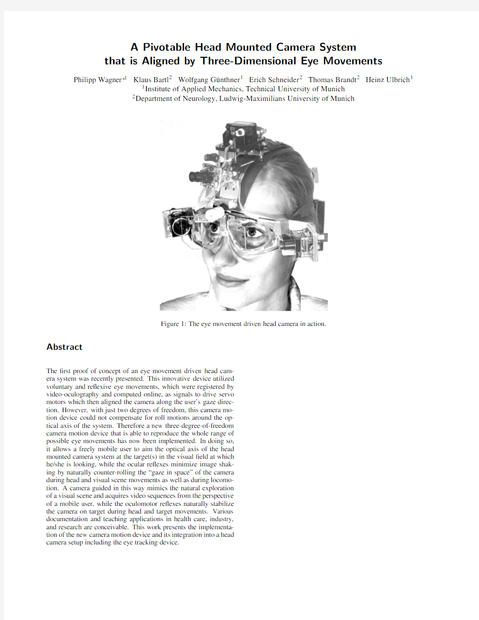
Figure1:The eye movement driven head camera in action.
Abstract
The?rst proof of concept of an eye movement driven head cam-
era system was recently presented.This innovative device utilized
voluntary and re?exive eye movements,which were registered by
video-oculography and computed online,as signals to drive servo
motors which then aligned the camera along the user’s gaze direc-
tion.However,with just two degrees of freedom,this camera mo-
tion device could not compensate for roll motions around the op-
tical axis of the system.Therefore a new three-degree-of-freedom
camera motion device that is able to reproduce the whole range of
possible eye movements has now been implemented.In doing so,
it allows a freely mobile user to aim the optical axis of the head
mounted camera system at the target(s)in the visual?eld at which
he/she is looking,while the ocular re?exes minimize image shak-
ing by naturally counter-rolling the“gaze in space”of the camera
during head and visual scene movements as well as during locomo-
tion.A camera guided in this way mimics the natural exploration
of a visual scene and acquires video sequences from the perspective
of a mobile user,while the oculomotor re?exes naturally stabilize
the camera on target during head and target movements.Various
documentation and teaching applications in health care,industry,
and research are conceivable.This work presents the implementa-
tion of the new camera motion device and its integration into a head
camera setup including the eye tracking device.
no effort is taken to stabilize the camera system.A stabilized cam-era system might,for example,consist of an inertial measurement unit and a motion device to rotate the camera into certain gaze di-rections.But even a stabilized camera system has the disadvantage that the recorded video stream will not contain the view of the user, since the eyes move relative to the head.Therefore two major ben-e?ts can be gained when human eye movements are used as input signals for the camera motion device:on the one hand,the bio-logical gaze stabilization can be used to keep the gaze direction of the video camera stable,and on the other,the user’s gaze direction will control the video camera so that the camera always sees what the user sees.A system guided in this way is the ideal tool for ad-dressing the increased awareness of the importance of using natural stimuli to study and model the visual system[Betsch et al.2004; Olshausen and Field2005].Such a camera overcomes the weak-nesses of other state-of-the-art techniques that provide only rough approximations of the retinal content.
A?rst proof of concept that orients a camera’s optical axis parallel to the user’s gaze direction was presented in[Schneider et al.2005]. This system used a video-oculography device(VOG)to detect eye motions of the user.From these eye motions the gaze direction of the user was calculated and used as an input signal for the camera motion device.Thus,the optical axis of the camera was kept par-allel to the human’s gaze direction.Assuming a suf?ciently small latency,the human gaze stabilization based on the vestibulo-ocular, optokinetic,and smooth pursuit re?exes can be used to stabilize the camera image.In this camera setup the biological equilibrium or-gan–the inner ear labyrinth–controls a technical system,hence rendering a technical inertial measurement unit obsolete.
Major drawbacks of the above-described system were a high la-tency in the range of100ms due to the use of eye tracking with standard video sampling rates(50Hz)as well as slow servo ac-tuators and electronics.Also the two-degree-of-freedom camera motion device was not able to follow all eye movements,since the human eye can rotate along three perpendicular axes.Therefore, a three-degree-of-freedom(3DoF)camera motion device has been designed to facilitate full camera control by means of eye move-ments.
This paper presents the design and implementation of a wearable head camera system that meets the requirements claimed above. Details of the eye tracking device that served as a basis for both mechanical support and motion control of the head camera are pre-sented in a companion paper[Boening et al.2006].A user wearing the complete system consisting of the eye tracker and the head cam-era is shown in Figure1.The focus of this work is on a?rst3DoF prototype that serves as an experimental platform as well as a pos-sible solution for a head camera system for consumer products.
2System Overview
The eye movement driven head-mounted camera consists of?ve main modules:
1.lightweight head mount
2.eye tracker
3.wearable computer
4.servo driver
5.gaze camera mount with Cardan joint
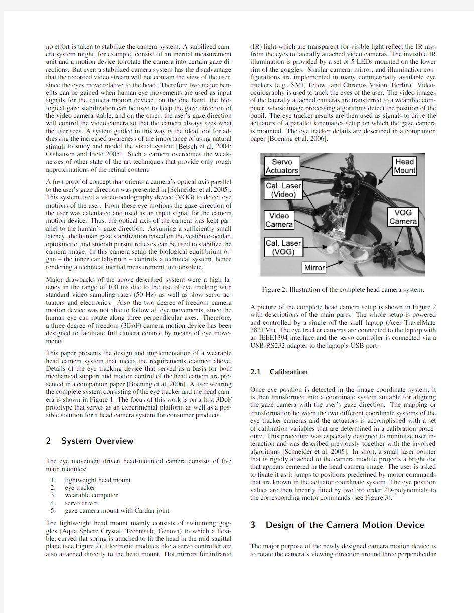
The lightweight head mount mainly consists of swimming gog-gles(Aqua Sphere Crystal,Technisub,Genova)to which a?exi-ble,curved?at spring is attached to?t the head in the mid-sagittal plane(see Figure2).Electronic modules like a servo controller are also attached directly to the head mount.Hot mirrors for infrared (IR)light which are transparent for visible light re?ect the IR rays from the eyes to laterally attached video cameras.The invisible IR illumination is provided by a set of5LEDs mounted on the lower rim of the goggles.Similar camera,mirror,and illumination con-?gurations are implemented in many commercially available eye trackers(e.g.,SMI,Teltow,and Chronos Vision,Berlin).Video-oculography is used to track the eyes of the user.The video images of the laterally attached cameras are transferred to a wearable com-puter,whose image processing algorithms detect the position of the pupil.The eye tracker results are then used as signals to drive the actuators of a parallel kinematics setup on which the gaze camera is mounted.The eye tracker details are described in a companion paper[Boening et al.
2006].
Figure2:Illustration of the complete head camera system.
A picture of the complete head camera setup is shown in Figure2 with descriptions of the main parts.The whole setup is powered and controlled by a single off-the-shelf laptop(Acer TravelMate 382TMi).The eye tracker cameras are connected to the laptop with an IEEE1394interface and the servo controller is connected via a USB-RS232-adapter to the laptop’s US
B port.
2.1Calibration
Once eye position is detected in the image coordinate system,it is then transformed into a coordinate system suitable for aligning the gaze camera with the user’s gaze direction.The mapping or transformation between the two different coordinate systems of the eye tracker cameras and the actuators is accomplished with a set of calibration variables that are determined in a calibration proce-dure.This procedure was especially designed to minimize user in-teraction and was described previously together with the involved algorithms[Schneider et al.2005].In short,a small laser pointer that is rigidly attached to the camera module projects a bright dot that appears centered in the head camera image.The user is asked to?xate it as it jumps to positions prede?ned by motor commands that are known in the actuator coordinate system.The eye position values are then linearly?tted by two3rd order2D-polynomials to the corresponding motor commands(see Figure3).
3Design of the Camera Motion Device The major purpose of the newly designed camera motion device is to rotate the camera’s viewing direction around three perpendicular
(x,y)
(x,y)
Figure3:Schematic setup of the calibration technique.The user ?xates a laser dot that is moved together with the pivotable camera. The mapping between measured eye positions in image coordinates and corresponding motor commands is achieved by3rd order poly-nomial?ts.
axes with kinematic properties that are similar to those of the hu-man oculomotor system.Panning camera motions are achieved by rotations around a vertical(pan)axis.For elevation movements the camera is rotated around the horizontal(tilt)axis,and?nally,the camera can also move around its optical(roll)axis.To describe the considerations that led to the presented design,some general solu-tions for camera motion devices will be discussed in this section. The construction of a small three-degree-of-freedom camera mo-tion device based on a serial design is described in[Mayol et al. 2000].The use of extremely small cameras allows the choice of servo actuators designed for miniature aircraft models.An impor-tant advantage of the presented serial construction is the linear be-havior and the simple inverse kinematics of the system.The nu-merous moving components,however,constitute the major disad-vantage of such a serial system.As only the?rst actuator of the system is stationary,it not only moves the camera,but also all other actuators,leading to a loss of acceleration and velocity capabilities of the system.To compensate for this loss of dynamic abilities, stronger and usually heavier actuators have to be chosen.Depend-ing on the structure connecting the different components,additional stiffness problems may easily occur.
Therefore,the desired system would have stationary actuators that do not perform motions as they do in a serial construction,in which the actuators themselves add to the inertia of the moving compo-nents.This can be achieved by using parallel structures at the cost of more complex kinematics[Riebe and Ulbrich2003].Parallel motion devices especially designed for use with cameras without this drawback can be found in[Truong et al.2000]as well as in[Gosselin and Hamel1994].Note that the system presented in[Truong et al.2000]is used as a stereo robot head,which is a common application of moving cameras(see also[Scassellati 1998]).These systems reach extremely high velocities and accel-erations.However,compared to the cameras used,the complete systems are fairly big.Furthermore,a complex kinematic structure that uses many mechanical linkages to move the camera becomes necessary.The kinematic components add weight to the construc-tion and may have or develop backlash.
Hence the design goal for the head camera system was to create a mechanism that on the one hand has the undoubted advantages of a parallel mechanism(stationary actuators)and on the other, avoids the described drawbacks(backlash and high number of link-ages).Furthermore,the construction has to be extremely compact and lightweight in order to affect the user as little as possible.
3.1Mechanical Setup
An early attempt to construct a two-degree-of-freedom head mounted camera system can be found in[Schneider et al.2005]. Here the camera was mounted on a Cardan joint,allowing the cam-era to perform motions around two perpendicular axes,namely the pan and tilt axes.Motions around the camera’s optical axis,the roll axis,were not possible.This concept proved to be precise and stiff.
A similar mechanism had already been implemented in a humanoid robot’s ankle joint([Gienger et al.2001]and[Gienger2005]).Dis-advantages were the non-linearities in the inverse kinematics and a smaller pivoting range than in serial motion devices.
After considering the issues discussed above,we decided to up-grade the design given in[Schneider et al.2005]with a third axis to a full three-degree-of-freedom motion device.As in the previous system,the pan and tilt servo actuators are kept stationary.A major requirement was to?nd a solution that kept the third actuator sta-tionary in the same location next to the other actuators.
The earlier system did not reach the velocities of the human eye (500deg/s,see[Leigh and Zee1999]),thus the next main require-ment was to implement a system that could reach dynamic proper-ties comparable to that of the human oculomotoric system.Further requirements were a lightweight and compact construction as well as backlash-free joints for increased system precision. Photographs of the newly developed camera motion device can be seen in Figure4and Figure5from different viewing perspectives. The main parts are denoted.The camera motion device has been designed as a modular setup,consisting of the Cardan module, the servo module,and the camera module,thus allowing the user to change these components easily to achieve another setup,e.g., a servo module with different actuators or another camera mod-ule.All servo actuators are mounted together in the servo module, which is connected to the base plate of the Cardan module.The third module is mainly the camera carrier with the camera and an optional laser mount for calibration.The most important part of the system is the Cardan module,which hosts a concentric Cardan joint.The outer Cardan joint consists of a ring connecting the steer-ing plate with the base which can be?xed to the ergonomic head mount.The ring can rotate around a vertical axis in the base(pan axis).The steering plate is connected to the ring with a pivot joint. This joint allows rotation along a horizontal axis through the ring (tilt axis)perpendicular to the pan axis.With this design three de-grees of freedom are realized for the steering plate,enabling the
Figure4:Prototype of the three-degree-of-freedom camera motion
device.
Figure5:Prototype of the camera motion device.Note the inner Cardan joint in comparison to a coin.
camera to move in different gaze directions.To perform these mo-tions,two servo actuators move the steering plate by push rods and universal joints.
To control motions around the camera’s optical axis,the inner Car-dan joint is induced.This joint connects the camera carrier with a shaft that is coupled to the servo actuator’s output shaft by a push rod.The roll actuator has been placed above the other two actuators to keep the space below the other actuators free.Thus,the camera motion device can be placed closer to the human eyes to reduce the parallax error.It is a drawback that a third push rod becomes nec-essary.With this setup the camera carrier,which is mounted on the steering plate with ball bearings,can be rotated around the roll axis independently of the steering plate’s current orientation.For any given gaze direction,the camera can be rolled around its optical axis.
To keep the Cardan joints as small as possible,the inner Cardan joint has a maximum outer diameter of just6mm,and the steel bolts have a diameter of0.8mm(see Figure5).The device is there-fore based on two parallel mechanisms,in which the outer joint in?uences the inner joint,while the outer joint is completely
inde-Figure6:Kinematics of the three-degree-of-freedom camera mo-tion device.The upper part of the?gure shows a CAD model of the device with the description of the axes and the Cardan angles. In the lower part of the?gure the pan tilt mechanism(right)and the roll mechanism(left)are shown.Other components have been hidden for easier understanding.
pendent of the inner joint.
Except for the servo module made of POM(polyoxymethylene), the complete setup is machined from aluminum.Lightweight design has been implemented wherever possible.All joints are equipped with miniature precision ball bearings.The overall mass of the setup is as small as160g,with the concentric Cardan module having a mass of only15g.If smaller and lighter servo actuators are used,the mass of the complete system could be reduced to less than100g.The camera module itself(Lechner CCTV MK-0326) weighs15g.
3.2Inverse Kinematics and Workspace Optimiza-
tion
The challenge of dealing with parallel systems is usually the com-plex inverse kinematics.The solution to this problem is therefore a major task in this area.In the presented camera motion device, two different mechanisms are combined so that they partly in?u-ence each other.The?rst mechanism is the already known parallel mechanism that combines the motions of the two actuators,which perform the pan and tilt motions of the steering plate,thus steering the camera into the desired gaze directions.This mechanism will be referred to as the pan tilt mechanism.For the camera motion device,the Cardan angle de?nition has been used.Here the angular motion along the pan axis is described with the Cardan angleα.For rotations around the horizontal tilt axis the Cardan angleβis used. The task of the inverse kinematics is to calculate the correct actua-tor anglesφ1andφ2for the left and the right servo actuators from the known Cardan anglesαandβ.A CAD model of the kinematics of the camera motion device is shown in Figure6.The described angles are denoted.Pan,tilt,and roll axes have been included to illustrate how the system functions.For the given kinematic struc-ture,an analytical solution has been derived.
The second mechanism basically consists of the inner Cardan joint that connects the camera carrier with the output shaft of the roll ac-tuator;it will be called the roll mechanism in the following.This mechanism transfers the rotational motionφ3of the roll actuator to the camera,thus leading to an angular camera motion with the Car-
dan angleγ.While the roll mechanism does not in?uence the kine-
matics of the pan tilt mechanism,the pan tilt mechanism strongly affects the roll mechanism.For any combination of Cardan angles αandβ,a new gaze direction is set,leading to new constraints for the roll mechanism.Thus,the actuator angleφ3not only depends
on the desired roll angleγ,but also on the current pan and tilt angles αandβ.
We will not focus here on the solution of the inverse kinematics,be-cause the calibration described in section2.1renders exact knowl-edge of the mechanical behavior unnecessary.With the given cali-bration a direct coordinate mapping from eye tracker camera space to the actuator anglesφ1andφ2is possible without the need to know the anglesαandβ.Nevertheless,if the head mounted camera sys-tem is used in the various?elds of oculomotor research which re-quire exact knowledge of the eye movement angles and velocities, the analytical solution of the inverse kinematics would help to mea-sure these relevant oculomotor variables.In this application,how-ever,the inverse kinematics of the pan tilt mechanism have only been used to optimize the workspace,which will be described in the following.
The desired workspace of the camera motion device has been cho-sen to be in the range of±45deg for all three Cardan anglesα,β,andγ.For the roll angle,this is more than the physiologically required range of±15deg[Tweed et al.1998];however,the range of±45deg leaves enough room for arti?cial augmentation of the physiologically restricted eye movements in roll by,for example,a gain enhancement.The roll angleγis not involved in the pan tilt mechanism and since it is therefore not limited by the constraints of the parallel kinematics,it has not been considered in the optimiza-tion.The angleγcan easily cover the given range of±45deg. Due to the kinematic constraints of the parallel pan tilt mechanism, the desired range cannot be reached in the?rst attempt.Hence,to enlarge the workspace of the pan tilt mechanism,an optimization algorithm has been used in combination with certain geometrical deliberations.The optimization aim was to maximize the number of possible combinations of the anglesαandβwhich the mechanism can adjust.To achieve this,certain geometrical parameters of the kinematics were subjected to the variations of the algorithm.The result of the workspace optimization is shown in Figure7.Every point in the diagram represents a certain gaze direction of the cam-era motion device.This gaze direction is described by the corre-sponding combination of certain anglesαandβ.The area inside the inner shape symbolizes the workspace of the?rst camera mo-tion device without geometrical optimizations(starting con?gura-tion).That is,the mechanism can adjust all combinations of angles αandβwithin the shape.Note that for greater absolute values of α,only small variations ofβare possible,and vice versa.The area inside the outer shape symbolizes the possible combinations ofαandβafter an optimization using the Implicit Filtering algorithm (optimized con?guration).A description of this algorithm can be found in[Choi et al.2001]and[Kelley1998].Note that almost any point in the complete area between?45and45deg can be achieved for both angles.The radius of the actuator levers in the?rst setup was chosen to be R=10.75mm.It is a trivial observation that for longer actuator levers,the workspace will become broader.To achieve a compromise between long actuator levers and a compact system,the new radius of the actuator levers in the optimization has been?xed to R=20mm.Additionally,the universal joints at the steering plates have been set into the plane that is described by the pan and tilt axes forαandβbeing equal to zero.In neutral position the push rods and the line between the universal joints at the steer-ing plate are nearly perpendicular.The other geometrical values for joint positions and servo positions have been optimized using the Implicit Filtering algorithm to?nd the ideal geometry in terms of maximization of the desired workspace.The proposed changes in the geometrical values are relatively small.In general,the algo-rithm suggests that the distance between the universal joints at the steering plate should be shortened and moved closer to the tilt axis. This result is not surprising.The most important advantage of the optimization,however,is that under the given constraints,optimum values can be derived for the geometry.
Figure7:Results of the optimization of the parallel camera motion device’s workspace.αdescribes the camera’s orientation around the vertical(pan)andβthe orientation around the horizontal(tilt) axis.The curves surround the area of possible combinations ofαandβof the parallel mechanism.The optimization was achieved using the Implicit Filtering algorithm.Note the difference between the area inside the starting con?guration line and the area inside the line of the optimized con?guration.
3.3Drive Speci?cation
The actuators must be able to reach high velocities and accelera-tions to move the selected camera so that it performs like the human oculomotor system.Other important requirements are low weight, small dimensions,and high reliability.After an online search on different actuator systems,we have chosen electric DC motors with reduction gears.The most appropriate actuators turned out to be servo actuators for model airplanes.A major advantage of these ac-tuators is the fact that DC motor,gear,and a position control are all integrated in one package,making the complete actuator extremely compact.Furthermore,these actuators deliver both high velocities and high torque.They are also almost backlash-free and contain a motion control system with position feedback through a poten-tiometer.Therefore,no additional sensors have to be used as limit or reference switches.In the?rst camera motion device[Schnei-der et al.2005]Graupner DS281Actuators,which belong to the smallest servo motors available,were used.The price paid for the small size and weight(9g)was a low maximum speed(250deg/s). Now as the system had to be capable of performing eye-like mo-tions,much faster actuators were needed.Especially during fast eye movements,the angular velocity of the camera was not high enough to deliver good enough image quality.So for the new prototype,the chosen actuators(Graupner DS3781,Kirchheim,Germany)are among the fastest servo actuators that still have a reasonable size and weight(1000deg/s at a mass of just28g).With these compo-nents a camera motion device can be demonstrated with dynamic properties that come close to or even excel those of the human eye.
4Electronic Setup
A major drawback of the?rst system described in[Schneider et al. 2005]was a high over-all latency due to high camera latencies and slow servo actuators and electronic devices.The over-all latency of that system was on the order of100ms and therefore more than an order of magnitude above the10ms latency of the vestibulo-ocular re?ex[Leigh and Zee1999].With this high latency,suf?cient im-age stabilization could not be achieved.An important milestone of development was therefore to minimize the over-all latency.
In a?rst step,we replaced the comparably slow(50Hz)analog video cameras of the underlying eye tracker system.The new sys-tem is equipped with a IEEE-1394digital camera(Flea,Pointgrey, Vancouver).With pixel binning it can operate at an image resolu-tion of320x240pixels and a frame rate of100Hz.
The off-the-shelf servo-controllers used in[Schneider et al.2005] were limited in their sampling rate to the standard remote-control pulse width modulation(PWM)rate of50Hz.The actuators used here(see section3.3),however,are capable of treating PWM sig-nals up to approximately400Hz.Besides,the baud rate supported by the previously used controller was limited to19200kBaud. Therefore,the latency for transmitting control commands via the RS232-interface to the controller was inacceptably high.
To overcome these limitations,a new servo controller based on a PIC18F4431microcontroller has been designed.It can control up to four servo actuators at arbitrary pulse rates.The maximum rate, however,is limited by the required PWM signal,which has a max-imum pulse width of2ms.Therefore,the sampling rate must be lower than500Hz to be able to generate separate pulses.In the given setup,a frame rate of300Hz has been chosen to ensure cor-rect functioning of the actuators.The servo controller is connected to a RS232interface working at115200kBaud.
Figure8:Schematic setup for latency measurements.A servo mo-tor rotates an arti?cial eye whose pupil is detected by an eye tracker system.Control commands for the head mounted camera are cal-culated from the pupil movements.Gyroscopes measuring the an-gular velocities are attached on both the arti?cial eye and the head mounted camera.
The controller board additionally serves as a power supply system for the actuators,the calibration laser,and the head mounted cam-era.A switching voltage regulator and a DC/DC-converter generate the required voltages from the voltage of the IEEE-1394connector. The calibration laser of the camera motion device is also switched on and off by the controller board.A Firewire-hub(Macally FH-220)is used to connect eye tracking cameras for both eyes.It is assembled together with the servo controller in a small plastic case and attached to the back of the head mount.
For the?rst tests on mobility and functionality,the system was con-nected to an Acer TravelMate382TMi Laptop(Intel Pentium M725 processor,1.6Ghz,400Mhz FSB,2MB L2cache,512MB DDR RAM).Since the laptop adheres to the“legacy-free”design con-siderations,a USB-to-RS232converter(Manhattan products Part 205146)has been used.It introduces an additional latency of ap-proximately1ms compared to a direct coupling with a RS232in-terface.A color analog video camera module with standard PAL output(Mintron MTV-03X10H)has been used as the gaze camera.
Figure9:Delay of the complete system:Measured angular veloc-ities(see Figure8)at3.33Hz.The solid black curve indicates the measured(raw)velocity of the head mounted camera.The dashed black curve shows the sine?t to this velocity from the regression calculation.The solid gray line indicates the measured velocity of the arti?cial eye,and the dashed gray line shows the corresponding sine?t.
5Ergonomic Head Mount
The lightweight head mount is attached to the eye tracker goggles. It consists of a curved aluminum plate on the front and a curved elastic plastic plate which continues onto the back of the head.The goggles and the head mount are connected by a frame joint,which can be adjusted and then rigidly?xed at an angle matching the wearer’s head geometry.The curved plastic plate,which is rigidly attached to the aluminum plate,extends beyond it to the back of the head.With this con?guration,the head mount also serves to stabi-lize the eye tracker goggles.An initially loose,pliable,broad strap is placed between the aluminum plate and the user’s head in order to increase the contact surface,thereby improving the comfort and wearability by decreasing the surface load on the head.Adjustable straps like those on a bicycle helmet can be tightened around the head to prevent slippage.The base plate of the camera motion de-vice described in section3.1is mounted above the user’s forehead on the curved metal plate of the head mount.For further adaptabil-ity to different head geometries,two slots down the aluminum plate allow the gaze camera position to be adjusted until appropriate;it is then rigidly?xed.Supply cables are attached to the aluminum and plastic plates,which also serve as carriers for electronic modules controlling the actuators,the eye tracker,the actuated camera,and the calibration laser.A small plastic case is attached to the outer side of the plastic plate in back.It contains the necessary electronic
components and acts as a cord grip for the supply line as well as a counterweight to the camera motion device in front.
5°
Figure10:Head camera view of the used calibration pattern.Dark dots are?xation targets,the bright spot is the laser projection. Crosshaired markers show the positions from automated target de-tection.Differences between?xation targets(dark)and actual cam-era position(bright)are a measurement for the precision of the com-plete system.
6Results
An overview of our?rst experiences and measurements with the head mounted camera system is given in this section.
6.1Latencies
To measure the latency of the complete system,we attached an ar-ti?cial eye to an additional actuator,which is controlled indepen-dently by a pro?le generator.We used sinusoidal pro?les at5fre-quencies ranging from1Hz to10Hz.The eye tracking system detects the arti?cial eye’s pupil as it would with a real eye.The detected eye position serves as input to control the head mounted camera.Both the angular velocities of the arti?cial eye and of the head mounted camera are synchronously measured by the attached, integrated gyroscopes(see Figure8).
We calculated the phase shift of both angular velocities by?tting sine curves to the measured(noisy)signals with means of regres-sion https://www.360docs.net/doc/585260466.html,ing the known frequency,we can compute the latency from the phase shift.Figure9shows the measurement val-ues at3.33Hz.
Our measurements at different frequencies yielded the following mean latencies:As a?rst major result the overall latency has been signi?cantly reduced compared to that of the?rst eye movement driven head camera.The latency of the new setup is relatively close to the la-tency of the human vestibulo-ocular re?ex,which is on the order of 10ms[Leigh and Zee1999].
6.2Precision
To measure the accuracy of the camera positioning,we calibrated the system as described in the above section2.1.A subject wearing the head mount was asked to?xate25targets in front of him/her (viewing distance1.18m).The targets were spread out regularly at distances of8.5degrees of viewing angle in each horizontal and vertical direction.At each?xation point,two images of the head mounted camera were recorded in fast sequence.The?rst image required no additional prerequisites,but for the second image,the calibration laser was?ashed for approximately100ms.This proce-dure allowed the automatic detection of both the?xation target and the alignment of the head mounted camera(indicated by the laser spot)by means of image processing.
Figure10shows a representative camera image after the analysis of one?xation of the precision measurement;the different locations of the target dot(black)and the bright laser clearly indicate the camera’s view direction.The deviations between target locations and the corresponding camera positions for all25?xation tasks are summarized in Figure6.2.This precision measurement yielded a mean value of0.5deg for all distances between the?xation tar-get and the camera alignment(accuracy)and a standard deviation (resolution)of0.25deg.
Figure11:Target points and camera directions for the precision measurement.Circles indicate the target points,which have to be ?xated by the subject.Crosses show the actual gaze camera align-ment.The mean distance between targets and corresponding cam-era positions is a measure of the spatial accuracy of the complete system.
7Conclusion
Video recordings from the subjective perspective of a mobile user are possible with this more advanced three-degree-of-freedom pro-
totype of a gaze-driven camera.The camera has proven to be usable with lower-frequency head movements and with ocular following as well as during locomotion.The calibration procedure required only minimal user interaction and therefore it did not distract the user from his main tasks.The accuracy of the whole system–includ-ing the user–is in the range of0.5deg,which is well within the 2deg of foveal vision.Such a camera system can already be used for documentation and teaching purposes in,e.g.,health care,qual-ity assurance,movie making,and even sports.A consumer product based on this prototype is also conceivable.Future developments will focus on improving the latency even further with faster eye tracker cameras,on implementing image processing mechanisms that detect eye tracker slippage during fast head movements,and on optimizing the ergonomic constraints. Acknowledgments
This study was supported by the Bayerische Forschungsstiftung (FORBIAS)and the Deutsche Forschungsgemeinschaft(GL342/1-1).We would like to thank one reviewer for valuable comments and Dr.Hamish MacDougall for fruitful discussions on the design of the eye tracker goggles.
References
B ETSCH,B.Y.,E INH¨AUSER,W.,K¨ORDING,K.P.,AND K¨ONIG,
P.2004.The world from a cat’s perspective–statistics of natural videos.Biol Cybern90,41–50.
B OENING,G.,B ARTL,K.,D ERA,T.,B ARDINS,S.,S CHNEI-
DER,E.,AND B RANDT,T.,2006.Mobile eye tracking as a basis for real-time control of a gaze driven head-mounted video camera.Unpublished.
C HOI,T.D.,E SLINGER,O.J.,G ILMORE,P.A.,K ELLEY,C.T.,
AND P ATRICK,H.A.,https://www.360docs.net/doc/585260466.html,er’s Guide to IFFCO.Center for Research in Scienti?c Computation,North Carolina State Uni-versity.
G IENGER,M.,L¨OFFLER,K.,AND P FEIFFER,F.2001.Towards
the design of a biped jogging robot.In International Conference on Robotics and Automation(ICRA).
G IENGER,M.,2005.Entwurf und Realisierung einer zweibeinigen
Laufmaschine.VDI-Berichte,Reihe1,Nr.378,VDI-Verlag.
G OSSELIN,C.M.,AND H AMEL,J.-F.1994.The agile eye:a
high-performance three-degree-of-freedom camera-orienting de-vice.In Proceeding of the IEEE International Conference on Robotics and Automation.
K ELLEY,C.T.,1998.Unconstrained implicit?ltering code:Im-plicit?ltering with sr1and bfgs quasi-newton methods.Source code online,https://www.360docs.net/doc/585260466.html,/ctk/darts/im?l.m.
L EIGH,R.J.,AND Z EE,D.S.,1999.The neurology of eye move-ments.Oxford University Press,New York,Oxford.
M AYOL,W.W.,T ORDOFF,B.,AND M URRAY,D.W.2000.
Wearable visual robots.In Proceedings of the International Sym-posium on Wearable Computing.
O LSHAUSEN,B.A.,AND F IELD,D.J.2005.How close are we to understanding v1?Neural Comput17,1665–1699.P ATLA,A.E.,AND V ICKERS,J.N.2003.How far ahead do we look when required to step on speci?c locations in the travel path during locomotion?Exp Brain Res148,133–138.
P ELZ,J.B.,AND C ANOSA,R.2001.Oculomotor behavior and perceptual strategies in complex tasks.Vision Res41,3587–3596.
R IEBE,S.,AND U LBRICH,H.,2003.Modelling and online-computation of the dynamics of a parallel kinematic with six-degrees-of-freedom.Archive of Applied Mechanics,V ol.72, No.11-12,Springer-Verlag,Berlin,Heidelberg,New York,July.
S CASSELLATI,B.,1998.A binocular,foveated active vision sys-tem.MIT AI Memo1628,March.
S CHNEIDER,E.,B ARTL,K.,B ARDINS,S.,D ERA,T.,B OEN-ING,G.,AND B RANDT,T.2005.Eye movement driven head-mounted camera:It looks where the eyes look.In Proceed-ings of the IEEE Conference on Systems,Man and Cybernetics (SMC2005),2437–2442.
T RUONG,H.,A BDALLAH,S.,R OUGEAUX,S.,AND Z ELINSKY,
A.2000.A novel mechanism for stereo active vision.In Pro-
ceedings of the Australian Conference on Robotics and Automa-tion(ACRA2000).
T WEED,D.,H ASLWANTER,T.,AND F ETTER,M.1998.Optimiz-ing gaze control in three dimensions.Science281,1363–1366.
民歌篇教案范文
民歌篇教案范文 1、喜欢聆听、演唱民歌及具有民族风格的通俗歌曲,愿意探索有关民歌的音乐文化知识。 2、掌握有关民歌的基本知识。 3、通过欣赏,初步感知南北民歌的风格特点,感受民族音乐与民俗风情的丰富多彩。 重点:着重欣赏广东民歌《对花》,同时听辨《槐花几时开》《拨根芦柴花》《上去高山望平川》《猜花》等民歌。 难点:本篇以“花”为立足点,使学生借此了解东南西北民歌的不同风格,感受民歌的绚丽风采。 一、导入: 1、欣赏流行音乐视频片段:《茉莉花》——梁静茹 师提问:大家熟悉这首流行歌吗?喜欢吗?
这首流行歌曲是中国江南民歌《茉莉花》改编而成,一曲茉莉花,芬芳香四方,这首脍炙人口的江苏民歌几乎是我们国家在重要事件和相关国际重要场合下的必奏之歌。在北京奥运会上,《茉莉花》作为主旋律背景音乐向世界展示了中国文化,让世界了解了中国。可见,民族音乐之于民族的重要性。 2、民歌是什么? 民歌是人民的歌、民族的歌,是真实反映劳动人民情感、生活的歌曲作品。民歌以口头传播,一传十十传百,一代传一代的传下去至今,每个民族都有自己的生活方式,并在代代积淀与传承中形成了自己独特的文化。不同的文化又赋予了音乐不同的形式和内涵,形成了风格迥异的民族音乐。它们是音乐文化的基础和源泉。 3、民歌的分类:山歌、号子、小调。 二、新授: 在中国的民歌中,“花”是一个最普遍的主题,其用法有三种:一是以花喻人,借花表法情爱;二是歌颂大自然,传授自然知识;三是借花起兴,以花为歌唱媒介,而花本身没有特定含义。
我们今天这堂课正是从“花”出发,了解东南西北民歌的不同风格,感受民歌的绚丽风采。(点出本课围绕的中心话题,引发学生的关注。) 1、以“花”为题材的各地民歌 ①、四川民歌《槐花几时开》 (介绍“晨歌”,聆听歌曲,体验歌曲中富有地方特色的“啥子”的唱段) ②、江苏民歌《拔根芦柴花》 (介绍“秧田歌”,聆听歌曲,了解歌词中出现的众多花名的意义) ③、青海民歌《上去高三望平川》 (介绍“河湟花儿”,聆听歌曲,谈谈自己所感受到的演唱风格) ④、辽宁民歌《猜花》
清华大学开题报告ppt
清华大学开题报告ppt 篇一:毕业论文开题报告 武汉工程大学计算机科学与工程学院 毕业论文开题报告 第 1 页共 4 页 (5)可以随时修改系统口令。 (6)灵活的数据备份、还原功能。 (7)系统最大限度地实现易安装性、易维护性和易操作性。 (8)系统运行稳定,安全可靠。 通过使用超市管理系统可以迅速提升超市的管理水平,降低经营成本,为提高效益和增强超市扩张能力,提供了有效的技术保障。本系统就是在这样的背景下提出的。另外在技术方面采用了较为先进的Java Swing技术和SQL Server XX,用来实现超市管理信息系统,包括系统登陆、基本资料、进货管理、销售管理、库存管理、系统维护、信息查询7个模块。 要求能够自觉运用数据库系统课程学习的理论知识指导软件设计;掌握信息管理系统的开发方法和步骤。整个应用系统的设计严格按照数据库设计的方法来进行,包括数据库的设计和应用程序的设计,两部分相辅相成。 数据库设计过程包含以下步骤:
需求分析:系统的目的、用户的各种需求、业务流程图、数据流程图; 概念结构设计:用E-R图来描述实体及实体间的联系; 逻辑结构设计:确定关系模式,各种约束的声明,如主码外码约束、唯一性约束、非空约束等。同时给出系统的功能模块组成图,系统各模块功能; 物理结构设计; 数据库实施; 数据库的实施阶段:数据库用SQL Server XX等创建,前端开发使用Java、.NET等实现。 通过此次课程设计提高自己独立分析问题、解决问题的能力。掌握从需求分析、数据库设计(概念设计、逻辑设计、物理设计)、编写程序、测试分析,撰写文档到最终答辩的整个过程。 参考文献: [1] 刘京华等. JAVA WEB整合开发王者归来[M].北京:清华大学出版社,XX [2] 王俊杰. 精通JAVA SCRIPT动态网页编程[M].北京:人民邮电出版社,XX [3] 李宁. Java Web编程实战宝典[M].北京:清华大学出版社,XX [4] 孙更新. Java程序开发大全[M].北京:中国铁道出
JavaScript设计模式
JavaScript设计模式的作用——提高代码的重用性,可读性,使代码更容易的维护和扩展。 1.单体模式,工厂模式,桥梁模式个人认为这个一个优秀前端必须掌握的模式,对抽象编程和接口编程都非常有好处。 2.装饰者模式和组合模式有很多相似的地方,它们都与所包装的对象实现同样的接口并且会把任何方法的调用传递给这些对象。装饰者模式和组合模式是本人描述的较吃力的两个模式,我个人其实也没用过,所以查了很多相关资料和文档,请大家海涵。 3.门面模式是个非常有意思的模式,几乎所有的JavaScript库都会用到这个模式,假如你有逆向思维或者逆向编程的经验,你会更容易理解这个模式(听起来有挑战,其实一接触你就知道这是个很简单的模式);还有配置器模式得和门面模式一块拿来说,这个模式对现有接口进行包装,合理运用可以很多程度上提高开发效率。这两个模式有相似的地方,所以一块理解的话相信都会很快上手的。 4.享元模式是一种以优化为目的的模式。 5.代理模式主要用于控制对象的访问,包括推迟对其创建需要耗用大量计算资源的类得实例化。 6.观察者模式用于对对象的状态进行观察,并且当它发生变化时能得到通知的方法。用于让对象对事件进行监听以便对其作出响应。观察者模式也被称为“订阅者模式”。 7.命令模式是对方法调用进行封装的方式,用命名模式可以对方法调用进行参数化和传递,然后在需要的时候再加以执行。 8.职责链模式用来消除请求的发送者和接收者之间的耦合。 JavaScript设计模式都有哪些? 单体(Singleton)模式:绝对是JavaScript中最基本最有用的模式。 单体在JavaScript的有多种用途,它用来划分命名空间。可以减少网页中全局变量的数量(在网页中使用全局变量有风险);可以在多人开发时避免代码的冲突(使用合理的命名空间)等等。 在中小型项目或者功能中,单体可以用作命名空间把自己的代码组织在一个全局变量名下;在稍大或者复杂的功能中,单体可以用来把相关代码组织在一起以便日后好维护。
各种系统架构图
各种系统架构图及其简介 1.Spring 架构图 Spring 是一个开源框架,是为了解决企业应用程序开发复杂性而创建的。框架的主要优势之一就是其分层架构,分层架构允许您选择使用哪一个组件,同时为J2EE 应用程序开发提供集成的框架。Spring 框架的功能可以用在任何 J2EE 服务器中,大多数功能也适用于不受管理的环境。Spring 的核心要点是:支持不绑定到特定J2EE 服务的可重用业务和数据访问对象。这样的对象可以在不同J2EE 环境(Web 或EJB )、独立应用程序、测试环境之间重用。 组成Spring 框架的每个模块(或组件)都可以单独存在,或者与其他一个或多个模块联合实现。每个模块的功能如下: ?核心容器:核心容器提供Spring 框架的基本功能。核心容器的主要组件是BeanFactory ,它是工厂模式的实现。BeanFactory 使用控制反转 (IOC )模式将应用程序的配置和依赖性规范与实际的应用程序代码分开。 ?Spring 上下文:Spring 上下文是一个配置文件,向Spring 框架提供上下文信息。Spring 上下文包括企业服务,例如JNDI 、EJB 、电子邮件、 国际化、校验和调度功能。
?Spring AOP :通过配置管理特性,Spring AOP 模块直接将面向方面的编程功能集成到了Spring 框架中。所以,可以很容易地使Spring 框架管理的任何对象支持AOP 。Spring AOP 模块为基于Spring 的应用程序中的对象提供了事务管理服务。通过使用Spring AOP ,不用依赖EJB 组件,就可以将声明性事务管理集成到应用程序中。 ?Spring DAO :JDBC DAO 抽象层提供了有意义的异常层次结构,可用该结构来管理异常处理和不同数据库供应商抛出的错误消息。异常层次结构简化了错误处理,并且极大地降低了需要编写的异常代码数量(例如打开和关闭连接)。Spring DAO 的面向JDBC 的异常遵从通用的DAO 异常层次结构。 ?Spring ORM :Spring 框架插入了若干个ORM 框架,从而提供了ORM 的对象关系工具,其中包括JDO 、Hibernate 和iBatis SQL Map 。所有这些都遵从Spring 的通用事务和DAO 异常层次结构。 2.ibatis 架构图 ibatis 是一个基于 Java 的持久层框架。 iBATIS 提供的持久层框架包括SQL Maps 和 Data Access Objects ( DAO ),同时还提供一个利用这个框架开发的 JPetStore 实例。 IBATIS :最大的优点是可以有效的控制sql 发送的数目,提高数据层的执行效率!它需要程序员自己去写sql 语句,不象hibernate 那样是完全面向对象的,自动化的,ibatis 是半自动化的,通过表和对象的映射以及手工书写的sql 语句,能够实现比hibernate 等更高的查询效率。
民歌篇教案
民歌篇教案 《xx四方》——民歌篇教学设计 【教学年级】:高一年级 【教学课时】:一课时 【设计思路】:通过聆听,了解民歌的风格特征,感受民歌的艺术魅力,培养学生对中国民歌的喜爱和兴趣,体现以音乐审美为核心的理念。通过民歌的学习让学生认识到:民族音乐是中华民族数千年来劳动人民智慧的结晶,是劳动人民创造的宝贵文化遗产,是中华民族传统文化的组成部分;同时帮助学生树立“音乐作为文化”和“文化中的音乐”的观念,培养学生“弘扬民族音乐文化”、理解多元文化的理念,从而达到理解和尊重多元的世界文化的目的。 【教学目标】: 、喜欢聆听、演唱民歌及具有民族风格的通俗歌曲,愿意探索有关民歌的音乐文化知识。 2、掌握有关民歌的基本知识。 3、通过欣赏,初步感知南北民歌的风格特点,感受民族音乐与民俗风情的丰富多彩。 【教学重点,难点】: 重点:着重欣赏广东民歌《对花》,同时听辨《槐花几时开》《拨根芦柴花》《上去高山望平川》《猜花》等民歌。 难点:本篇以“花”为立足点,使学生借此了解东南西 xx民歌的不同风格,感受民歌的绚丽风采。 【教学准备】:多媒体、视频、音频等 【教学过程】:
一、导入: 、欣赏流行音乐视频片段:《茉莉花》——梁静茹师提问:大家熟悉这首流行歌吗?喜欢吗? 这首流行歌曲是中国江南民歌《茉莉花》改编而成,一曲茉莉花,芬芳香四方,这首脍炙人口的江苏民歌几乎是我们国家在重要事件和相关国际重要场合下的必奏之歌。在北京奥运会上,《茉莉花》作为主旋律背景音乐向世界展示了中国文化,让世界了解了中国。可见,民族音乐之于民族的重要性。 2、民歌是什么? 民歌是人民的歌、民族的歌,是真实反映劳动人民情感、生活的歌曲作品。民歌以口头传播,一传十十传百,一代传一代的传下去至今,每个民族都有自己的生活方式,并在代代积淀与传承中形成了自己独特的文化。不同的文化又赋予了音乐不同的形式和内涵,形成了风格迥异的民族音乐。它们是音乐文化的基础和源泉。 3、民歌的分类:山歌、号子、小调。 二、新授: 在中国的民歌中,“花”是一个最普遍的主题,其用法 有三种:一是以花喻人,借花表法情爱;二是歌颂大自然,传授自然知识;三是借花起兴,以花为歌唱媒介,而花本身没有特定含义。 我们今天这堂课正是从“花”出发,了解东南西北民歌的不同风格,感受民歌的绚丽风采。(点出本课围绕的中心话题,引发学生的关注。) 、以“花”为题材的各地民歌 ①、xx民歌《槐花几时开》 (介绍“晨歌”,聆听歌曲,体验歌曲中富有地方特色的“啥子”的唱段) ②、xx民歌《拔根芦柴花》
分层架构与业务逻辑实现方式
分层架构与业务逻辑实现方式
分层架构与业务逻辑实现方式 一、分层架构 在当今软件系统中,常用的软件架构思想就是分层,分层思想是现代软件架构的主要思想。无论是企业级应用系统(如:CRM,ERP,OA,电子商务平台),专用软件(如:OS、SVN、IDE 等),还有协议之类(TCP/IP,OSI等)绝大部分都采用分层架构思想进行设计的。 分层(Layer)不一定就是人们常说的二,三层,多层系统,因为这些说法都是分层架构的一些具体表现形式,分层是一种设计思想,也可以称之为一种软件架构模式(Pattern),这种思想的核心在于:划分系统的职责(Responsibility),如果这个系统的职责你分析清楚了,你的基于设计思路差不多就定下来了。你可以去看看,很多的现在代软件,不是一定是web方面。例如:SVN这样的源代码管理软件、 图一:SVN架构图
.NET Framework也是分层,Eclipse也是,TCP/IP更加是,还有像操作系统(OS)、编译器(Compiler),很多流行框架(Framework)也是分层。其实,MVC不也是分层,也就是把模型(Model)、视图(View)、控制器(Controller)三个不同职责分开。 那我们看看今天的企业级应用系统(很多说是web项目,其他我不认为是这样,因为web只是一种外在表现形式,我们可以用desktop程序,flash等作为表现形式),企业级应用系统很多人一说就是三层架构,其实确实也是这样的。即:表示层,业务层,数据层。当然还有其他的分层,如:表示层,服务层(服务外观层),业务逻辑层,数据映射层,数据层。也有分成:表现层,中间层,数据访问层等等。(注意这些都是逻辑上分层结构一般用Layer,物理上的分层结构,一般讲的是部署结构一般用tier)总体上都可以看成是三层:表现层,业务逻辑层(也可以说是领域层或领域逻辑层),数据层。像Spring,Structs、ORM 等一些框架,他们都是在不同的层上的相关实现技术。 二、业务逻辑几种实现方式 现在我们再看看,企业级系统中最核心是哪一层?肯定是业务层,因为企业级系统主要是与业务打交道(其实几乎所有软件都是实现业务,企业级系统业务逻辑主要偏向于商业逻辑,其他系统,像游戏,自动化控制、支撑系统等把业务看成是算法),而且业务是每个系统都不尽相同的。“业务逻辑是最没有逻辑的东西” [Fowler PoEAA,2003]。而且企业级系统的变化与改变大多都在业务层上。那么,做好企业级系统,首先主要分析好业务系统。你可以看看,现今所有的框架在整体结构(spring,structs,等要求系统按MVC结构来开发),表示层(jquery,extjs等),与数据层(ORM之类)做得最多,有没有业务的框架?(有,但是很少,而且只能是业务比较有规律的地方,像一些财务系统,有些权限系统,当然还有工作流系统)因为业务逻辑每个系统都很可能不一样,没办法通用。那么有什么办法以比较好的方式实现业务逻辑呢。现在终于说到主要问题上来了:也就是业务逻辑(Business Logic)的实现方式,也叫做领域逻辑(Domain Logic)的实现方式。一般来说,有以下几种: 1.事务脚本(Transaction scripts) 2.领域模型(Domain Model)
花飘四方
《花飘四方》——民歌篇教学设计 【教学年级】:高一年级 【教学课时】:一课时 【设计思路】:通过聆听,了解民歌的风格特征,感受民歌的艺术魅力,培养学生对中国民歌的喜爱和兴趣,体现以音乐审美为核心的理念。通过民歌的学习让学生认识到:民族音乐是中华民族数千年来劳动人民智慧的结晶,是劳动人民创造的宝贵文化遗产,是中华民族传统文化的组成部分;同时帮助学生树立“音乐作为文化”和“文化中的音乐”的观念,培养学生“弘扬民族音乐文化”、理解多元文化的理念,从而达到理解和尊重多元的世界文化的目的。 【教学目标】: 1、喜欢聆听、演唱民歌及具有民族风格的通俗歌曲,愿意探索有关民歌的音乐文化知识。 2、掌握有关民歌的基本知识。 3、通过欣赏,初步感知南北民歌的风格特点,感受民族音乐与民俗风情的丰富多彩。 【教学重点,难点】: 重点:着重欣赏广东民歌《对花》,同时听辨《槐花几时开》《拨根芦柴花》《上去高山望平川》《猜花》等民歌。 难点:本篇以“花”为立足点,使学生借此了解东南西北民歌的不同风格,感受民歌的绚丽风采。
【教学准备】:多媒体、视频、音频等 【教学过程】: 一、导入: 1、欣赏流行音乐视频片段:《茉莉花》——梁静茹 师提问:大家熟悉这首流行歌吗?喜欢吗? 这首流行歌曲是中国江南民歌《茉莉花》改编而成,一曲茉莉花,芬芳香四方,这首脍炙人口的江苏民歌几乎是我们国家在重要事件和相关国际重要场合下的必奏之歌。在北京奥运会上,《茉莉花》作为主旋律背景音乐向世界展示了中国文化,让世界了解了中国。可见,民族音乐之于民族的重要性。 2、民歌是什么? 民歌是人民的歌、民族的歌,是真实反映劳动人民情感、生活的歌曲作品。民歌以口头传播,一传十十传百,一代传一代的传下去至今,每个民族都有自己的生活方式,并在代代积淀与传承中形成了自己独特的文化。不同的文化又赋予了音乐不同的形式和内涵,形成了风格迥异的民族音乐。它们是音乐文化的基础和源泉。 3、民歌的分类:山歌、号子、小调。 二、新授: 在中国的民歌中,“花”是一个最普遍的主题,其用法有三种:一是以花喻人,借花表法情爱;二是歌颂大自然,传授自然知识;三是借花起兴,以花为歌唱媒介,而花本身没有特定含义。 我们今天这堂课正是从“花”出发,了解东南西北民歌的不同风格,感
分层架构模式.NET架构和模式
分层架构模式:.NET架构和模式 疯狂代码 https://www.360docs.net/doc/585260466.html,/ ?:http:/https://www.360docs.net/doc/585260466.html,/Programing/Article60049.html 什么是架构 软件Software体系结构通常被称为架构指可以预制和可重构软件Software框架结构架构尚处在发展期对于其定义学术界尚未形成个统意见而区别角度视点也会造成软件Software体系结构区别理解以下是些主流标准观点 ANSI/IEEE 610.12-1990软件Software工程标准词汇对于体系结构定义是:“体系架构是以构件、构件的间关系、构件和环境的间关系为内容某系统基本组织结构以及知道上述内容设计和演化原理(principle)” Mary Shaw和David Garlan认为软件Software体系结构是软件Software设计过程中超越计算中算法设计和数据结构设计个层次体系结构问题包括各个方面组织和全局控制结构通信协议、同步数据存储给设计元素分配特定功能设计元素组织规模和性能在各设计方案的间进行选择Garlan & Shaw模型基本思想是:软件Software体系结构={构件(component),连接件(connector)约束(constrain)}.其中构件可以是组代码如模块;也可以是个独立如数据库服务器连接件可以是过程、管道、远程过程(RPC)等用于表示构件的间相互作用约束般为对象连接时规则或指明构件连接形式和条件例如上层构件可要求下层构件服务反的不行;两对象不得递规地发送消息;代码复制迁移致性约束;什么条件下此种连接无效等 有关架构定义还有很多其他观点比如Bass定义、Booch & Rumbaugh &Jacobson定义、Perry & Wolf模型[7]、Boehm模型等等虽然各种定义关键架构角度区别研究对象也略有侧重但其核心内容都是软件 Software系统结构其中以Garlan & Shaw模型为代表强调了体系结构基本要素是构件、连接件及其约束(或者连接语义)这些定义大部分是从构造角度来甚至软件Software体系结构而IEEE定义不仅强调了系统基本组成同时强调了体系结构环境即和外界交互 什么是模式 模式(Pattern)概念最早由建筑大师Christopher Alexander于 2十世纪 7十年代提出应用于建筑领域 8十年代中期由Ward Cunningham和Kent Beck将其思想引入到软件Software领域Christopher Alexander将模式分为 3个部分:首先是周境(Context也可以称着上下文),指模式在何种状况下发生作用;其 2是动机( of Forces),意指问题或预期目标;其 3是解决方案(Solution),指平衡各动机或解决所阐述问题个构造或配置(Configuration)他提出模式是表示周境、动机、解决方案 3个方面关系个规则每个模式描述了个在某种周境下不断重复发生问题以及该问题解决方案核心所在模式即是个事物(thing)又是个过程(process)不仅描述该事物本身而且提出了通过怎样过程来产生该事物这定义已被软件Software界广为接受 软件Software模式应用对软件Software开发产生了重大作用主要表现在: 软件Software模式是人们在长期设计软件Software、管理组织软件Software开发等实战中大量经验提炼和抽象是复用软件Software设计思路方法、过程管理经验有力工具模式类似于拳击中组合拳它提供了系列软件Software开发中思维套路如通过模式使用有利于在复杂系统中产生简洁、精巧设计
十 大 经 典 排 序 算 法 总 结 超 详 细
前端资源收集 前端资-源收集 收集的资-源 44个 Javascript 变态题解析 javascript 变态题解析 正则表达式收集 正则表达式收集 十大经典排序算法总结(JavaScript描述)排序算法的总结 前端工具库汇总 前端工具库总结 怎么学JavaScript? 学习javascript 的学习指导 不定期更新 JavaScript技巧 javascript 编码技巧总结 H5项目常见问题汇总及解决方案 高质量的常见问题汇总 廖雪峰的 git 教-程 Git忽略规则.gitignore梳理 git 配置提交规则 全局环境,执行环境
setTimeout promises 很酷,但很多人并没有理解就在用了 promises 使用错误汇总 promises webpack 2 中文文档 输入url后的加载过程 详细解答从输入URL 到页面显示的过程 数组Array.prototype方法 介绍了数组的一些新的方法 移动端真机调试 Web 客户端存储 ESLint中文指南 webpack 2 集成ESLint react-webpack2-skeleton webpack 2 react 成功案例,包括热加载 cookie 小结 CSS定制多行省略 Ajax 知识体系大梳理 js+nodejs完成文件上传 用 webpack 实现持久化缓存 搜罗一切webpack的好文章好工具 深入理解 CSS:字体度量、line-height 和 vertical-align
原生JS中DOM节点相关API合集 正则表达式前端使用手册 聊一聊H5应用缓存-Manifest fetch进阶指南 mozilla 开发者网络 深入理解javascript原型和闭包系列JavaScript深入系列 深度长文 JavaScript数组所有API全解密你真的懂 JavaScript 的正则吗?webpack2 终极优化 文件上传那些事儿 写给前端工程师的DNS基础知识 初识weex(前端视角) - 环境搭建 前端命名规范 正则表达式 总有你要的编程书单(GitHub )JavaScript深入系列 javascript 的一些功能点 如何在小程序中调用本地接口 移动端浏览器调试方法汇总 HTML5移动开发中的input输入框类型 互联网协议入门
系统架构分层设计
系统架构分层设计 本文讨论关于项目系统架构的拆分模型,阐述每个层次(layer)的作用,以及面向SOA编程提供服务的方式。
服务端架构解决之道 大家看到这张图,用了一个形象的比喻来体现传统的服务端软件。最下层是操作系统,通常是Linux,最上层是我们的业务功能和服务。在服务端架构,很习惯用增加一个架构层次的方式来解决问题。例如缓存层、数据访问层。在架构上按照自己的意愿去搭建不同层次的衔接环节,使架构具有足够的灵活性和扩展性。即时堆成这样,它依旧是非常合理的。 MVC Framkwrok
# Model与Controller通信 Model与Controller之间是用实线表示,这表明Model并不能随意的访问Controller,但是有时Controller是需要接收Model层的消息的。在MVC模式中,要实现Model层到Controller层的通信,使用了一种类似广播的方式。Model中数据变化时,Model会发出一条广播,然后对这个Model感兴趣的Controller就会收到广播并告诉对应View改变现实方式。
MVC中的Controller,即控制器,控制着整个程序的逻辑和Model如何显示到View层。Controller把Model和View连接起来,让我们可以在View上看到Controller想要Model层现实的样子。 # View与Controller通信 在程序过程中,View层其实是需要与Controller通信的,当然View层不可能直接调用Controller的某个方法来处理用户点击事件,因为View不知道该使用Controller中的哪个方法。因此,使用了一种叫做Target的方式来处理这个问题,Controller会事先告诉View,如果触发了某个事件,View就会把这个动作转给Target。然后Controller运行完该方法,处理好这个时间以后就会告诉Veiw。
javascript设计模式介绍(二) 构造函数模式
本文由我司收集整编,推荐下载,如有疑问,请与我司联系 javascript 设计模式介绍(二)构造函数模式 2016/04/22 0 我们可以通过创建自定义的构造函数,从而定义自定义对象类型 的属性和方法。 例如: function Person(name.age,sex){https://www.360docs.net/doc/585260466.html, = name;this.age = age;this.sex = sex;this.sayName = function(){ alert(https://www.360docs.net/doc/585260466.html,); }}然后我们实例一个Personvar person1 = new Person(john ,18, 男var person1 = new Person(Rose ,17, 女 我们注意到,Person()中的代码: 没有显式地创建对象; 直接将属性和方法赋给了this 对象; 没有return 语句。 此外,还应该注意到函数名Person 使用的是大写字母P。按照惯例,构造函数始 终都应该以一个大写字母开头,而非构造函数则应该以一个小写字母开头。这个做 法借鉴自其他OO 语言,主要是为了区别于ECMAScript 中的其他函数;因为构造 函数本身也是函数,只不过可以用来创建对象而已。 要创建Person 的新实例,必须使用new 操作符。以这种方式调用构造函数实际 上会经历以下4 个步骤:(1) 创建一个新对象;(2) 将构造函数的作用域赋给新对象 (因此this 就指向了这个新对象);(3) 执行构造函数中的代码(为这个新对象添加 属性);(4) 返回新对象。 person1 和person2 分别保存着Person 的一个不同的实例。这两个对象都有一个constructor(构造函数)属性,该属性指向Person,如下所示。 alert(person1.constructor == Person); //true alert(person2.constructor == Person); //true 对象的constructor 属性最初是用来标识对象类型的。但是,提到检测对象类型, 还是instanceof 操作符要更可靠一些。我们在这个例子中创建的所有对象既是Object 的实例,同时也是Person 的实例,这一点通过instanceof 操作符可以得到验 证。
MVC模式与三层架构整合
MVC模式与三层架构结合 经过老师与同学们的长期讨论,我们决定在项目的开发过程中应用MVC模式与三层架构结合的方式来实现我们架构的设计。这样种有两个好处:首先是可以实现多个视图,为我们开发不同的视图提供了很大的便利,使得我们在完成Web设计后没有必要在去设计Wap,减少了部分工作量;其次是运用三层架构,使结构层次清晰,各层之间能够并行设计;最后是采用这样的设计方式可以增加我们代码的重用性,减少耦合。 一、MVC模式和三层架构 MVC 模式包括三个部分, 即模型( Model) 、视图( View) 和控制( Controller) , 分别对应于内部数据、数据表示和输入/ 输出控制部分。MVC 模式的一般结构如图1 所示。 图1.MVC模式各部分的关系和功能 MVC 设计模式从早期的客户/ 服务器应用发展而来, 因此, 它采用的是两层架构设计。但由于三层架构是对两层架构的延伸, 所以还是可以将MVC 应用于三层架构的Web 应用中。MVC 与三层架构相互结合补充, 已经成为Web 应用开发的重要模式。MVC 模式与三层架构设计之间的关系如图2所示。 图2.MVC模式与三层架构之间的关系 二、架构设计 这里的架构设计与上次的三层架构概要设计大体类似,唯一不同的在于表示层。在这里我们将表示层分为了视图与控制器。其中视图完成页面的显示功能,而控制器主要完成视图与表示层逻辑的分离,拦截用户请求,组合模型与视图并返回相应视图给用户。 模块划分及交互设计 根据前面的讨论以及上次的架构概要设计文档,可在宏观上将整个系统分为以下几个模块: 实体类模块——一组实体类的集合,负责整个系统中数据的封装及传递。 数据访问层接口族——一组接口的集合,表示数据访问层的接口。
软件体系结构的风格和设计模式等
1.软件体系结构的性质、研究意义和目标是什么? 性质:计算机体系结构是程序员所看到的计算机的属性,即概念性结构与功能特性。强调整体与部分,部分与部分的关系;研究系统构成的方法学;提倡多角度研究系统。 为什么研究软件体系结构? 软件系统要满足一定的需求(功能和质量)。随着软件系统的日益复杂,公众对软件的要求已不局限于功能上的满足,而是更加注重质量。 软件的质量受到软件体系结构的限制,或者说体系结构的选择受到要达到的质量特征的影响。 软件体系结构是软件系统的高层结构,高度抽象,超越算法和数据结构,试图在软件需求与软件设计之间架起一座桥梁,解决结构和需求向实现平坦过渡。 现在软件产生的问题: ◎软件成本日益增长 ◎开发进度难以控制 在软件开发过程中,用户需求变化等各种意想不到的情况层出不穷,令软件开发过程很难保证按预定的计划实现,给项目计划和论证工作带来了很大的困难。 ◎软件质量差 缺乏工程化思想的指导,程序员以自己的想法去代替用户对软件的需求,软件设计带有随意性,很多功能只是程序员的“一厢情愿”而已。 ◎软件维护困难 特别是在软件使用过程中,原来的开发人员可能因各种原因已经离开原来的开发组织,使得软件几乎不可维护 2. 软件体系结构风格是描述某一特定应用领域中系统组织方式的惯用模式。 体系结构风格反映了领域中众多系统所共有的结构和语义特性,并指导如何将各个模块和子系统有效地组织成一个完整的系统。 管道-过滤器风格:缺乏交互性,常用于通信领域和编译器 事件驱动风格:易于完成并发多任务,具有良好的交互性,但对计算机系统的控制能力弱,很难共享数据。 分层风格:系统分成许多层,每层为上层服务,同时获取下层的服务。典型应用是网络协议。仓库风格:数据单元被共享。常用于专家系统,如自然语言理解和模式识别。 3.3 客户/服务器风格 C/S体系结构定义了工作站如何与服务器相连,以实现数据和应用分布到多个处理机上。 C/S体系结构有三个主要组成部分:数据库服务器、客户应用程序和网络。 服务器 (1)数据库安全性的要求; (2)数据库访问并发性的控制;
三层架构和其优点
三层架构及其优点 (2009-04-01 22:54:37) 标签: 三层架构是: 一:界面层 界面层提供给用户一个视觉上的界面,通过界面层,用户输入数据、获取数据。界面层同时也提供一定的安全性,确保用户不用看到不必要的机密信息。 二:逻辑层 逻辑层是界面层和数据层的桥梁,它响应界面层的用户请求,执行任务并从数据层抓取数据,并将必要的数据传送给界面层。 三:数据层 数据层定义、维护数据的完整性、安全性,它响应逻辑层的请求,访问数据。这一层通常由大型的数据库服务器实现,如Oracle 、Sybase、MS SQl Server等。 ------ 从开发角度和应用角度来看,三层架构比双层或单层结构都有更大的优势。三层结构适合群体开发,每人可以有不同的分工,协同工作使效率倍增。开发双层或单层应用时,每个开发人员都应对系统有较深的理解,能力要求很高,开发三层应用时,则可以结合多方面的人才,只需少数人对系统全面了解,从一定程度工降低了开发的难度。 三层架构属于瘦客户的模式,用户端只需一个较小的硬盘、较小的内存、较慢的CPU就可以获得不错的性能。相比之下,单层或胖客户对面器的要求太高。 三层架构的另一个优点在于可以更好的支持分布式计算环境。逻辑层的应用程序可以有多个机器上运行,充分利用网络的计算功能。分布式计算的潜力巨大,远比升级CPU有效。 三层架构的最大优点是它的安全性。用户端只能通过逻辑层来访问数据层,减少了入口点,把很多危
险的系统功能都屏蔽了。 另外三层架构还可以支持如下功能:Remote Access(远程访问资料),例如可透过Internet存取远程数据库;High Performance(提升运算效率)解决集中式运算(Centralize)及主从式架构(Client-Server)中,数据库主机的运算负担,降低数据库主机的Connection Load,并可藉由增加App Server处理众多的数据处理要求,这一点跟前面讲到的分布式计算提高运算能力是一个道理;Client端发出Request(工作要求)后,便可离线,交由App Server和DataBase Server共同把工作完成,减少Client端的等待时间;这个功能我觉得应用场合不是很多,自己感受也不是很深刻,从理论上是成立的。 --fadeless摘自网络。 三层架构 三层系统的分层式结构 三层架构(3-tier application) 通常意义上的三层架构就是将整个业务应用划分为:表现层(UI)、业务逻辑层(BLL)、数据访问层(DAL)。区分层次的目的即为了“高内聚,低耦合”的思想。 目录 展开 概念简介 1、表现层(UI):通俗讲就是展现给用户的界面,即用户在使用一个系统的时候他的所见所得。 2、业务逻辑层(BLL):针对具体问题的操作,也可以说是对数据层的操作,对
软件架构设计模式
软件架构设计模式
软件架构设计模式 随着面向对象技术的发展和广泛应用,设计模式不再是一个新兴的名词,它已逐步成为系统架构人员、设计人员、分析人员以及程序开发人员所需掌握的基本技能之一。设计模式已广泛应用于面向对象的设计和开发,成为面向对象领域的一个重要组成部分。设计模式通常可分为三类:创建型模式、结构型模式和行为型模式。 1.创建型模式概述 创建型模式(Creational Pattern)对类的实例化过程及对象的创建过程进行了抽象,能够使软件模块做到与对象的创建和组织无关。创建型模式隐藏了对象的创建细节,通过隐藏对象如何被创建和组合在一起达到使整个系统独立的目的。在掌握创建型模式时,需要回答以下三个问题:创建什么(What)、由谁创建(Who)和何时创建(When)。创建型模式主要包括简单工厂模式、工厂方法模式、抽象工厂模式、建造者模式、原型模式、单例模式。以下介绍其中使用频率较高的几种模式,包括简单工厂模式、工厂方法模式、抽象工厂模式、单例模式。 1.1 简单工厂模式 简单工厂模式(Simple Fatory Pattern),又称静态工厂方法模式(Static Factoty Method Pattern),属于类创建型模式。在简单工厂模式中,定义一个类,可以根据参数的不同返回不同的类的实例,这些类具有公共的父类和一些公共的方法。简单工厂模式不属于GoF设计模式,它是最简单的工厂模式。简单工厂模式专门定义一个类来负责创建其他类的实例,这个类称为工厂类,被创建的实例通常都具有共同的父类。 在简单工厂模式中,工厂类包含必要的判断逻辑,决定在什么时候创建哪一个产品类实例,客户端可以免除直接创建产品对象的责任,而仅仅“消费”产品,简单工厂模式通过这种方式实现了对责任的划分。但是由于工厂类集中了所有产品创建逻辑,一旦不能正常工作,整个系统都要受到影响;同时系统扩展较为困难,一
javascript设计模式
【Javascript设计模式1】-单例模式 《parctical common lisp》的作者曾说,如果你需要一种模式,那一定是哪里出了问题。他所说的问题是指因为语言的天生缺陷,不得不去寻求和总结一种通用的解决方案。 不管是弱类型或强类型,静态或动态语言,命令式或说明式语言、每种语言都有天生的优缺点。一个牙买加运动员,在短跑甚至拳击方面有一些优势,在练瑜伽上就欠缺一些。 术士和暗影牧师很容易成为一个出色的辅助,而一个背着梅肯满地图飞的敌法就会略显尴尬。换到程序中, 静态语言里可能需要花很多功夫来实现装饰者,而js由于能随时往对象上面扔方法,以至于装饰者模式在js里成了鸡肋。 讲javascript设计模式的书还比较少. Pro javaScript Design Patterns.是比较经典的一本,但是它里面的例子举得比较啰嗦,所以结合我在工作中写过的代码,把我的理解总结一下。如果我的理解出现了偏差,请不吝指正。 一单例模式 单例模式的定义是产生一个类的唯一实例,但js本身是一种“无类”语言。很多讲js设计模式的文章把{}当成一个单例来使用也勉强说得通。因为js生成对象的方式有很多种,我们来看下另一种更有意义的单例。 有这样一个常见的需求,点击某个按钮的时候需要在页面弹出一个遮罩层。比如https://www.360docs.net/doc/585260466.html,点击登录的时候. 这个生成灰色背景遮罩层的代码是很好写的.
问题是, 这个遮罩层是全局唯一的, 那么每次调用createMask都会创建一个新的div, 虽然可以在隐藏遮罩层的把它remove掉. 但显然这样做不合理. 再看下第二种方案, 在页面的一开始就创建好这个div. 然后用一个变量引用它. 这样确实在页面只会创建一个遮罩层div, 但是另外一个问题随之而来, 也许我们永远都不需要这个遮罩层, 那又浪费掉一个div, 对dom节点的任何操作都应该非常吝啬. 如果可以借助一个变量. 来判断是否已经创建过div呢? 看起来不错, 到这里的确完成了一个产生单列对象的函数. 我们再仔细看这段代码有什么不妥.
各技术框架架构图
1.Spring 架构图 Spring 是一个开源框架,是为了解决企业应用程序开发复杂性而创建的。框架的主要优势之一就是其分层架构,分层架构允许您选择使用哪一个组件,同时为J2EE 应用程序开发提供集成的框架。Spring 框架的功能可以用在任何J2EE 服务器中,大多数功能也适用于不受管理的环境。Spring 的核心要点是:支持不绑定到特定J2EE 服务的可重用业务和数据访问对象。这样的对象可以在不同J2EE 环境(Web或EJB )、独立应用程序、测试环境之间重用。 组成Spring 框架的每个模块(或组件)都可以单独存在,或者与其他一个或多个模块联合实现。每个模块的功能如下: ?核心容器:核心容器提供Spring 框架的基本功能。核心容器的主要组件是BeanFactory ,它是工厂模式的实现。BeanFactory 使用控制反转(IOC )模式将应用程序的配置和依赖性规范与实际的应用程序代码分开。 ?Spring 上下文:Spring 上下文是一个配置文件,向Spring 框架提供上下文信息。 Spring 上下文包括企业服务,例如JNDI 、EJB 、电子邮件、国际化、校验和调度功能。 ?Spring AOP :通过配置管理特性,Spring AOP 模块直接将面向方面的编程功能集成到了Spring 框架中。所以,可以很容易地使Spring 框架管理的任何对象支 持AOP 。Spring AOP 模块为基于Spring 的应用程序中的对象提供了事务管理服 务。通过使用Spring AOP ,不用依赖EJB 组件,就可以将声明性事务管理集成到应用程序中。 ?Spring DAO :JDBC DAO 抽象层提供了有意义的异常层次结构,可用该结构来管理异常处理和不同数据库供应商抛出的错误消息。异常层次结构简化了错误处理, 并且极大地降低了需要编写的异常代码数量(例如打开和关闭连接)。Spring DAO 的面向JDBC 的异常遵从通用的DAO 异常层次结构。 ?Spring ORM :Spring 框架插入了若干个ORM 框架,从而提供了ORM 的对象关系工具,其中包括JDO 、Hibernate 和iBatis SQL Map 。所有这些都遵从Spring 的通用事务和DAO 异常层次结构。 2.ibatis 架构图 ibatis 是一个基于Java的持久层框架。 iBATIS 提供的持久层框架包括 SQL Maps 和Data Access Objects ( DAO ),同时还提供一个利用这个框架开发的 JPetStore 实例。
三层架构图
一.三层架构图 二.系统各层次职责 1.UI(User Interface)层的职责是数据的展现和采集,数据采集的结果通常以Entity object提交给BL层处理。Service Interface侧层用于将业务 服务(如WebServices)。 2.BL(Business Logic)层的职责是按预定的业务逻辑处理UI层提交的请求。 (1)Business Function 子层负责基本业务功能的实现。 (2)Business Flow 子层负责将Business Function子层提供的多个基本业务功能组织成一个完整的业务流。(Transaction只能在Business Flow 3.ResourceAccess层的职责是提供全面的资源访问功能支持,并向上层屏蔽资源的来源。 (1)BEM(Business Entity Manager)子层采用DataAccess子层和ServiceAccess子层来提供业务需要的基础数据/资源访问能力。 (2)DataAccess子层负责从数据库中存取资源,并向BEM子层屏蔽所有的SQL语句以及数据库类型差异。 DB Adapter子层负责屏蔽数据库类型的差异。 ORM子层负责提供对象-关系映射的功能。 Relation子层提供ORM无法完成的基于关系(Relation)的数据访问功能。 (3)ServiceAccess子层用于以SOA的方式从外部系统获取资源。 注:Service Entrance用于简化对Service的访问,它相当于Service的代理,客户直接使用Service Entrance就可以访问系统发布的服务。Servi
Java程序员必备的15个框架,前3个地位无可动摇!
Java程序员必备的15个框架,前3个地位无可动摇! Java 程序员方向太多,且不说移动开发、大数据、区块链、人工智能这些,大部分Java 程序员都是Java Web/后端开发。那作为一名Java Web 开发程序员必须需要熟悉哪些框架呢? 今天,栈长我给大家列举了一些通用的、必须掌握的框架,学会这些,20K+ 不是问题。 1.Spring 毫无疑问,Spring 框架现在是Java 后端框架家族里面最强大的一个,其拥有IOC 和AOP 两大利器,大大简化了软件开发复杂性。并且,Spring 现在能与所有主流开发框架集成,可谓是一个万能框架,Spring 让JAVA 开发变得更多简单。 官网: https://spring.io/projects/spring-framework 源码: https://https://www.360docs.net/doc/585260466.html,/spring-projects/spring-framework 推荐: 2.Spring MVC
Spring MVC 是一个MVC 开源框架,用来代替Struts。它是Spring 项目里面的一个重要组成部分,能与Spring IOC 容器紧密结合,以及拥有松耦合、方便配置、代码分离等特点,让JAVA 程序员开发WEB 项目变得更加容易。 官网: https://spring.io/projects/spring-framework 源码: https://https://www.360docs.net/doc/585260466.html,/spring-projects/spring-framework 3.Spring Boot Spring Boot 是Spring 开源组织下的一个子项目,也是Spring 组件一站式解决方案,主要是为了简化使用Spring 框架的难度,简省繁重的配置。 Spring Boot提供了各种组件的启动器(starters),开发者只要能配置好对应组件参数,Spring Boot 就会自动配置,让开发者能快速搭建依赖于Spring 组件的Java 项目。官网: https://spring.io/projects/spring-boot 源码: https://https://www.360docs.net/doc/585260466.html,/spring-projects/spring-boot 推荐: