驱动桥的构造外文文献翻译、中英文翻译、外文翻译
附录A
The structure of driving axle
The driving axle is in the power power transmission the terminal, its basic function increases the torque which transmits by the drive shaft or the transmission gearbox, and power reasonable assignment for left and right driving gear, moreover also withstands the function vertical sets up, the longitudinal force and the transverse force between the road surface and the frame or the automobile body.The driving axle generally by the main gear box, the differential device, the wheel transmission device and the driving axle shell and so on is composed.
1.Driving axle design:
The driving axle design must satisfy following basic request:
1). Choice main reduction gear ratios ought to be able to guarantee the automobile has the best power and the fuel economy.
2). External dimensions must be small, guaranteed has the necessity ground clearance.
3). Gears and other transmission piece works do steadily, the noise is small.
4). Has the high transmission efficiency under each kind of rotational speed and the load.
5). Under the guarantee enough intensity, the rigidity condition, should make every effort the quality to be small, under the reed the quality should be as far as possible small in particular, improves the automobile smoothness.
6). Coordinated with the suspension fork guidance organization movement, regarding changes the driving axle, but also should coordinate with the rotation gear movement.
7). Structures are simple, the processing technology capability is good, the manufacture is easy, disassembling, the adjustment is convenient.
2.Driving axle classification
The driving axle minute non-separation type with separates the type two big kinds.
1).Non-separation type driving axle
The non-separation type driving axle also is called the integral-type driving axle, its rear axle drive pipe and main gear box shell with shaft casing rigidly connected whole Liang,
thus the both sides rear axle and the driving gear swing related, passes the elastic part and the frame is connected.It by the driving axle shell 1, the main gear box, the differential device and the rear axle is composed.
2). Separation type driving axle
The driving axle uses the independent suspension fork, namely the main gear box shell fixes on the frame, the both sides rear axle and the driving gear can be opposite in the rolling plane in the chassis have the relative motion to be called the separation type driving axle.
In order to coordinates with the independent suspension fork, fixes the main gear box shell in the frame (or automobile body) on, the driving axle shell partition and through the hinge joint, or no longer has the driving axle shell other parts besides the main gear box shell.In order to meet the need which about the driving gear independence beats, between the differential device and between wheel rear axle each section connects with the universal joint.
3.Drive axle of composition
Mainly by the reducer drive, and half axle and drive axle shell, etc.
1) .Main reducer
The speed reducer is usually used to change the direction of transmission, reduce speed and increase torque, guarantee cars have enough force and appropriate speed. Main reducer, have more single type, double, double speed reducer, wheel edges.
a). Single main reducer
By a reduction gear reducer realization of single reducer, called. Its simple structure, light weight, dongfeng BQl090, light, medium sized truck was widely used in automobile.
b). Double main reducer
In some large trucks, load demand is bigger than the slow, with single main reducer drive, driven gear diameter increases, affect to the ground clearance drive, so using twice. Usually called doublestage reducer. Two groups of double reduction gear reducer, increasing torsional twice slowdown.
To improve the tapered gear pair of meshing smoothness and strength, the level of spiral bevel gears reduction gear pair is. Second gear pair is helical gears for support.
Active tapered gear rotating, drive driven circular gear rotating, thus completing silver. Level Article 2 the initiative of cylindrical gears and driven tapered gear coaxial and rotate together, and bring about a follower of cylindrical gears rotate, 2. Because a follower of
cylindrical gears installed in differential shell, so, when a follower of cylindrical gears turning, through the differential and half shaft is driven wheel rotation.
2).Differential
Around half shaft are used to connect differential wheel, can make the sides with different velocity rotating torque simultaneously. Ensure the normal scroll wheel. Some more, in the car driver bridge or in the breakthrough of thansfer transmission shaft with differential between, also called the bridge between differential. Its role in the car is in turn or flat road to drive wheels, and generate differential between the role.
Current domestic cars and other cars are adopted symmetric bevel gear ordinary differential. Symmetrical type gear differential planetary gear, half of planetary gear axle shaft gear, or a cross (direct axis) and differential shell, etc.
Most current car using differential planetary gear, ordinary bevel gear differential by two or four conical planetary gear and planetary gear axle, two cone half shaft gear and differential shell, etc.
3). Half axle
Half shaft are coming to the differential wheel, drive torque to move the car wheel rotation, the solid shaft. Due to the different structure, installation of hub axial force and the different also. Therefore, half shaft are divided into the floating, use, three/four floating three types.
a). Howo fou-point suspending half axle
General big, medium-sized cars are adopted the floating structure. Half of the spline shaft inside with the half shaft with differential gears connected to the end of the half shaft are forging flanges, bolts and wheel connection. Hub through two far apart WenCheng tapered roller bearings in half a collar. Half a collar and driving axle shell pressure to drive, composition. Use this form, half shaft bearing no direct link with the bridge housing, half shaft driving torque and not only bear any moment under this half shaft are called "the floating" half axle. The so-called "float" means half shaft are not bending load.
The float, the half axle shaft for lugs and made one. But there are some heavy trucks to lugs, and made the individual parts of the spline shaft in the half. Therefore, both ends of the spline shaft is used, can HuanTou.
b). Use half axle
Use of half axle within the same with the client, not withstand float bending-torsional. The client through a direct bearing on the inside of half axle shell. This means that will
support the half axle under bending moment. Therefore, the half sleeve torque, except under bending moment, local use half shaft is called. This structure is mainly used for certain.
The red flag brand limousines CA7560 type of thing. The half shaft are not bending moment, the client will inherit all external use, so called bending support.
c). 3/4 floating half axle
Three-quarters of floating half shaft are short of bending degree between use and the floating. This type of half axle currently used in XiaoWoChe, only on individual applications, such as M20 type car. Warsaw,
4). The bridge housing
a). Integral bridge housing
Integral bridge housing for the intensity and rigidity, and facilitate the good performance of the installation, adjustment and maintenance, and widely used. Integral bridge housing for manufacturing methods, which can be divided into different midway through the whole cast type, the steel casting and stamping steel welding etc.
b). Drive axle shell segmented
Section type bridge housing generally fall into two, one will DuanLianCheng two by bolts. Bridge housing is segmented to casting and machining.
附录B
驱动桥的构造
驱动桥处于动力传动系的末端,其基本功能是增大由传动轴或变速器传来的转矩,并将动力合理的分配给左、右驱动轮,另外还承受作用于路面和车架或车身之间的垂直立、纵向力和横向力。驱动桥一般由主减速器、差速器、车轮传动装置和驱动桥壳等组成。
驱动桥的设计:
驱动桥设计应当满足如下基本要求:
选择的主减速比应能保证汽车具有最佳的动力性和燃料经济性。
(2)外形尺寸要小,保证有必要的离地间隙。
(3)齿轮及其他传动件工作平稳,噪声小。
(4)在各种转速和载荷下具有高的传动效率。
(5)在保证足够的强度、刚度条件下,应力求质量小,尤其是簧下质量应尽量小,以改善汽车平顺性。
(6)与悬架导向机构运动协调,对于转向驱动桥,还应与转向机构运动相协调。
(7)结构简单,加工工艺性好,制造容易,拆装、调整方便。
驱动桥的分类
驱动桥分非断开式与断开式两大类。
1、非断开式驱动桥
非断开式驱动桥也称为整体式驱动桥,其半轴套管与主减速器壳均与轴壳刚性地相连一个整体梁,因而两侧的半轴和驱动轮相关地摆动,通过弹性元件与车架相连。它由驱动桥壳1,主减速器,差速器和半轴组成。
2、断开式驱动桥
驱动桥采用独立悬架,即主减速器壳固定在车架上,两侧的半轴和驱动轮能在横向平面相对于车体有相对运动的则称为断开式驱动桥。
为了与独立悬架相配合,将主减速器壳固定在车架(或车身)上,驱动桥壳分段并通过铰链连接,或除主减速器壳外不再有驱动桥壳的其它部分。为了适应驱动轮独立上下跳动的需要,差速器与车轮之间的半轴各段之间用万向节连接。
驱动桥的组成
驱动桥主要由主减速器、差速器、半轴和驱动桥壳等组成。
1、主减速器
主减速器一般用来改变传动方向,降低转速,增大扭矩,保证汽车有足够的驱动力和适当的速皮。主减速器类型较多,有单级、双级、双速、轮边减速器等。
(1)单级主减速器
由一对减速齿轮实现减速的装置,称为单级减速器。其结构简单,重量轻,东风BQl090型等轻、中型载重汽车上应用广泛。
(2)双级主减速器
对一些载重较大的载重汽车,要求较大的减速比,用单级主减速器传动,则从动齿轮的直径就必须增大,会影响驱动桥的离地间隙,所以采用两次减速。通常称为双级减速器。双级减速器有两组减速齿轮,实现两次减速增扭。
为提高锥形齿轮副的啮合平稳性和强度,第一级减速齿轮副是螺旋锥齿轮。二级齿轮副是斜齿因拄齿轮。
主动圆锥齿轮旋转,带动从动圆银齿轮旋转,从而完成一级减速。第二级减速的主动圆柱齿轮与从动圆锥齿轮同轴而一起旋转,并带动从动圆柱齿轮旋转,进行第二级减速。因从动圆柱齿轮安装于差速器外壳上,所以,当从动圆柱齿轮转动时,通过差速器和半轴即驱动车轮转动。
2、差速器
差速器用以连接左右半轴,可使两侧车轮以不同角速度旋转同时传递扭矩。保证车轮的正常滚动。有的多桥驱动的汽车,在分动器内或在贯通式传动的轴间也装有差速器,称为桥间差速器。其作用是在汽车转弯或在不平坦的路面上行驶时,使前后驱动车轮之间产生差速作用。
目前国产轿车及其它类汽车基本都采用了对称式锥齿轮普通差速器。对称式锥齿轮差速器由行星齿轮、半轴齿轮、行星齿轮轴(十字轴或一根直销轴)和差速器壳等组成。
目前大多数汽车采用行星齿轮式差速器,普通锥齿轮差速器由两个或四个圆锥行星齿轮、行星齿轮轴、两个圆锥半轴齿轮和左右差速器壳等组成。
3、半轴
半轴是将差速器传来的扭矩再传给车轮,驱动车轮旋转,推动汽车行驶的实心轴。由于轮毂的安装结构不同,而半轴的受力情况也不同。所以,半轴分为全浮式、半浮式、3/4浮式三种型式。
(1)全浮式半轴
一般大、中型汽车均采用全浮式结构。半轴的内端用花键与差速器的半轴齿轮相连接,半轴的外端锻出凸缘,用螺栓和轮毂连接。轮毂通过两个相距较远的圆锥滚子轴承文承在半轴套管上。半轴套管与后桥壳压配成一体,组成驱动桥壳。用这样的支承形式,半轴与桥壳没有直接联系,使半轴只承受驱动扭矩而不承受任何弯矩,这种半轴称为“全浮式”半轴。所谓“浮”意即半轴不受弯曲载荷。
全浮式半轴,外端为凸缘盘与轴制成一体。但也有一些载重汽车把凸缘制成单独零件,并借花键套合在半轴外端。因而,半轴的两端都是花键,可以换头使用。
(2)半浮式半轴
半浮式半轴的内端与全浮式的一样,不承受弯扭。其外端通过一个轴承直接支承在半轴外壳的内侧。这种支承方式将使半轴外端承受弯矩。因此,这种半袖除传递扭矩外,还局部地承受弯矩,故称为半浮式半轴。这种结构型式主要用于小客车。
图示为红旗牌CA7560型高级轿车的驱动桥。其半轴内端不受弯矩,而外端却要承受全部弯矩,所以称为半浮式支承。
(3)3/4浮式半轴
3/4浮式半轴是受弯短的程度介于半浮式和全浮式之间。此式半轴目前应用不多,只在个别小卧车上应用,如华沙M20型汽车。
(4)桥壳
1)整体式桥壳
整体式桥壳因强度和刚度性能好,便于主减速器的安装、调整和维修,而得到广泛应用。整体式桥壳因制造方法不同,可分为整体铸造式、中段铸造压入钢管式和钢板冲压焊接式等。
2)分段式驱动桥壳
分段式桥壳一般分为两段,由螺栓1将两段连成一体。分段式桥壳比较易于铸造和加工。
土木工程类专业英文文献及翻译
PA VEMENT PROBLEMS CAUSED BY COLLAPSIBLE SUBGRADES By Sandra L. Houston,1 Associate Member, ASCE (Reviewed by the Highway Division) ABSTRACT: Problem subgrade materials consisting of collapsible soils are com- mon in arid environments, which have climatic conditions and depositional and weathering processes favorable to their formation. Included herein is a discussion of predictive techniques that use commonly available laboratory equipment and testing methods for obtaining reliable estimates of the volume change for these problem soils. A method for predicting relevant stresses and corresponding collapse strains for typical pavement subgrades is presented. Relatively simple methods of evaluating potential volume change, based on results of familiar laboratory tests, are used. INTRODUCTION When a soil is given free access to water, it may decrease in volume, increase in volume, or do nothing. A soil that increases in volume is called a swelling or expansive soil, and a soil that decreases in volume is called a collapsible soil. The amount of volume change that occurs depends on the soil type and structure, the initial soil density, the imposed stress state, and the degree and extent of wetting. Subgrade materials comprised of soils that change volume upon wetting have caused distress to highways since the be- ginning of the professional practice and have cost many millions of dollars in roadway repairs. The prediction of the volume changes that may occur in the field is the first step in making an economic decision for dealing with these problem subgrade materials. Each project will have different design considerations, economic con- straints, and risk factors that will have to be taken into account. However, with a reliable method for making volume change predictions, the best design relative to the subgrade soils becomes a matter of economic comparison, and a much more rational design approach may be made. For example, typical techniques for dealing with expansive clays include: (1) In situ treatments with substances such as lime, cement, or fly-ash; (2) seepage barriers and/ or drainage systems; or (3) a computing of the serviceability loss and a mod- ification of the design to "accept" the anticipated expansion. In order to make the most economical decision, the amount of volume change (especially non- uniform volume change) must be accurately estimated, and the degree of road roughness evaluated from these data. Similarly, alternative design techniques are available for any roadway problem. The emphasis here will be placed on presenting economical and simple methods for: (1) Determining whether the subgrade materials are collapsible; and (2) estimating the amount of volume change that is likely to occur in the 'Asst. Prof., Ctr. for Advanced Res. in Transp., Arizona State Univ., Tempe, AZ 85287. Note. Discussion open until April 1, 1989. To extend the closing date one month,
土木工程外文翻译
转型衰退时期的土木工程研究 Sergios Lambropoulosa[1], John-Paris Pantouvakisb, Marina Marinellic 摘要 最近的全球经济和金融危机导致许多国家的经济陷入衰退,特别是在欧盟的周边。这些国家目前面临的民用建筑基础设施的公共投资和私人投资显著收缩,导致在民事特别是在民用建筑方向的失业。因此,在所有国家在经济衰退的专业发展对于土木工程应届毕业生来说是努力和资历的不相称的研究,因为他们很少有机会在实践中积累经验和知识,这些逐渐成为过时的经验和知识。在这种情况下,对于技术性大学在国家经济衰退的计划和实施的土木工程研究大纲的一个实质性的改革势在必行。目的是使毕业生拓宽他们的专业活动的范围,提高他们的就业能力。 在本文中,提出了土木工程研究课程的不断扩大,特别是在发展的光毕业生的潜在的项目,计划和投资组合管理。在这个方向上,一个全面的文献回顾,包括ASCE体为第二十一世纪,IPMA的能力的基础知识,建议在其他:显著增加所提供的模块和项目管理在战略管理中添加新的模块,领导行为,配送管理,组织和环境等;提供足够的专业训练五年的大学的研究;并由专业机构促进应届大学生认证。建议通过改革教学大纲为土木工程研究目前由国家技术提供了例证雅典大学。 1引言 土木工程研究(CES)蓬勃发展,是在第二次世界大战后。土木工程师的出现最初是由重建被摧毁的巨大需求所致,目的是更多和更好的社会追求。但是很快,这种演变一个长期的趋势,因为政府为了努力实现经济发展,采取了全世界的凯恩斯主义的理论,即公共基础设施投资作为动力。首先积极的结果导致公民为了更好的生活条件(住房,旅游等)和增加私人投资基础设施而创造机会。这些现象再国家的发展中尤为为明显。虽然前景并不明朗(例如,世界石油危机在70年代),在80年代领先的国家采用新自由主义经济的方法(如里根经济政策),这是最近的金融危机及金融危机造成的后果(即收缩的基础设施投资,在技术部门的高失业率),消除发展前途无限的误区。 技术教育的大学所认可的大量研究土木工程部。旧学校拓展专业并且新的学校建成,并招收许多学生。由于高的职业声望,薪酬,吸引高质量的学校的学生。在工程量的增加和科学技术的发展,导致到极强的专业性,无论是在研究还是工作当中。结构工程师,液压工程师,交通工程师等,都属于土木工程。试图在不同的国家采用专业性的权利,不同的解决方案,,从一个统一的大学学历和广泛的专业化的一般职业许可证。这个问题在许多其他行业成为关键。国际专业协会的专家和机构所确定的国家性检查机构,经过考试后,他们证明不仅是行业的新来者,而且专家通过时间来确定进展情况。尽管在很多情况下,这些证书虽然没有国家接受,他们赞赏和公认的世界。 在试图改革大学研究(不仅在土木工程)更接近市场需求的过程中,欧盟确定了1999博洛尼亚宣言,它引入了一个二能级系统。第一级度(例如,一个三年的学士)是进入
驱动桥外文翻译
驱动桥设计 随着汽车对安全、节能、环保的不断重视,汽车后桥作为整车的一个关键部件,其产品的质量对整车的安全使用及整车性能的影响是非常大的,因而对汽车后桥进行有效的优化设计计算是非常必要的。 驱动桥处于动力传动系的末端,其基本功能是增大由传动轴或变速器传来的转矩,并将动力合理地分配给左、右驱动轮,另外还承受作用于路面和车架或车身之间的垂直力力和横向力。驱动桥一般由主减速器、差速器、车轮传动装置和驱动桥壳等组成。 驱动桥作为汽车四大总成之一,它的性能的好坏直接影响整车性能,而对于载重汽车显得尤为重要。驱动桥设计应当满足如下基本要求: 1、符合现代汽车设计的一般理论。 2、外形尺寸要小,保证有必要的离地间隙。 3、合适的主减速比,以保证汽车的动力性和燃料经济性。 4、在各种转速和载荷下具有高的传动效率。 5、在保证足够的强度、刚度条件下,力求质量小,结构简单,加工工艺性 好,制造容易,拆装,调整方便。 6、与悬架导向机构运动协调,对于转向驱动桥,还应与转向机构运动协调。智能电子技术在汽车上得以推广使得汽车在安全行驶和其它功能更上一层楼。通过各种传感器实现自动驾驶。除些之外智能汽车装备有多种传感器能充分感知交通设施及环境的信息并能随时判断车辆及驾驶员是否处于危险之中,具备自主寻路、导航、避撞、不停车收费等功能。有效提高运输过程中的安全,减少驾驶员的操纵疲劳度,提高乘客的舒适度。当然蓄电池是电动汽车的关键,电动汽车用的蓄电池主要有:铅酸蓄电池、镍镉蓄电池、钠硫蓄电池、钠硫蓄电池、锂电池、锌—空气电池、飞轮电池、燃料电池和太阳能电池等。在诸多种电池中,燃料电池是迄今为止最有希望解决汽车能源短缺问题的动力源。燃料电池具有高效无污染的特性,不同于其他蓄电池,其不需要充电,只要外部不断地供给燃料,就能连续稳定地发电。燃料电池汽车(FCEV)具有可与内燃机汽车媲美的动力性能,在排放、燃油经济性方面明显优于内燃机车辆。
土木工程岩土类毕业设计外文翻译
姓名: 学号: 10447425 X X 大学 毕业设计(论文)外文翻译 (2014届) 外文题目Developments in excavation bracing systems 译文题目开挖工程支撑体系的发展 外文出处Tunnelling and Underground Space Technology 31 (2012) 107–116 学生XXX 学院XXXX 专业班级XXXXX 校内指导教师XXX 专业技术职务XXXXX 校外指导老师专业技术职务 二○一三年十二月
开挖工程支撑体系的发展 1.引言 几乎所有土木工程建设项目(如建筑物,道路,隧道,桥梁,污水处理厂,管道,下水道)都涉及泥土挖掘的一些工程量。往往由于由相邻的结构,特性线,或使用权空间的限制,必须要一个土地固定系统,以允许土壤被挖掘到所需的深度。历史上,许多挖掘支撑系统已经开发出来。其中,现在比较常见的几种方法是:板桩,钻孔桩墙,泥浆墙。 土地固定系统的选择是由技术性能要求和施工可行性(例如手段,方法)决定的,包括执行的可靠性,而成本考虑了这些之后,其他问题也得到解决。通常环境后果(用于处理废泥浆和钻井液如监管要求)也非常被关注(邱阳、1998)。 土地固定系统通常是建设项目的较大的一个组成部分。如果不能按时完成项目,将极大地影响总成本。通常首先建造支撑,在许多情况下,临时支撑系统是用于支持在挖掘以允许进行不断施工,直到永久系统被构造。临时系统可以被去除或留在原处。 打桩时,因撞击或振动它们可能会被赶入到位。在一般情况下,振动是最昂贵的方法,但只适合于松散颗粒材料,土壤中具有较高电阻(例如,通过鹅卵石)的不能使用。采用打入桩系统通常是中间的成本和适合于软沉积物(包括粘性和非粘性),只要该矿床是免费的鹅卵石或更大的岩石。 通常,垂直元素(例如桩)的前安装挖掘工程和水平元件(如内部支撑或绑回)被安装为挖掘工程的进行下去,从而限制了跨距长度,以便减少在垂直开发弯矩元素。在填充情况下,桩可先设置,从在斜坡的底部其嵌入悬挑起来,安装作为填充进步水平元素(如搭背或土钉)。如果滞后是用来保持垂直元素之间的土壤中,它被安装为挖掘工程的进行下去,或之前以填补位置。 吉尔- 马丁等人(2010)提供了一个数值计算程序,以获取圆形桩承受轴向载荷和统一标志(如悬臂桩)的单轴弯矩的最佳纵筋。他们开发的两种优化流程:用一个或两个直径为纵向钢筋。优化增强模式允许大量减少的设计要求钢筋的用量,这些减少纵向钢筋可达到50%相对传统的,均匀分布的加固方案。 加固桩集中纵向钢筋最佳的位置在受拉区。除了节约钢筋,所述非对称加强钢筋图案提高抗弯刚度,通过增加转动惯量的转化部分的时刻。这种增加的刚性可能会在一段时间内增加的变形与蠕变相关的费用。评估相对于传统的非对称加强桩的优点,对称,钢筋桩被服务的条件下全面测试来完成的,这种试验是为了验证结构的可行性和取得的变形的原位测量。 基于现场试验中,用于优化的加强图案的优点浇铸钻出孔(CIDH)在巴塞罗那的
土木工程外文翻译.doc
项目成本控制 一、引言 项目是企业形象的窗口和效益的源泉。随着市场竞争日趋激烈,工程质量、文明施工要求不断提高,材料价格波动起伏,以及其他种种不确定因素的影响,使得项目运作处于较为严峻的环境之中。由此可见项目的成本控制是贯穿在工程建设自招投标阶段直到竣工验收的全过程,它是企业全面成本管理的重要环节,必须在组织和控制措施上给于高度的重视,以期达到提高企业经济效益的目的。 二、概述 工程施工项目成本控制,指在项目成本在成本发生和形成过程中,对生产经营所消耗的人力资源、物资资源和费用开支,进行指导、监督、调节和限制,及时预防、发现和纠正偏差从而把各项费用控制在计划成本的预定目标之内,以达到保证企业生产经营效益的目的。 三、施工企业成本控制原则 施工企业的成本控制是以施工项目成本控制为中心,施工项目成本控制原则是企业成本管理的基础和核心,施工企业项目经理部在对项目施工过程进行成本控制时,必须遵循以下基本原则。 3.1 成本最低化原则。施工项目成本控制的根本目的,在于通过成本管理的各种手段,促进不断降低施工项目成本,以达到可能实现最低的目标成本的要求。在实行成本最低化原则时,应注意降低成本的可能性和合理的成本最低化。一方面挖掘各种降低成本的能力,使可能性变为现实;另一方面要从实际出发,制定通过主观努力可能达到合理的最低成本水平。 3.2 全面成本控制原则。全面成本管理是全企业、全员和全过程的管理,亦称“三全”管理。项目成本的全员控制有一个系统的实质性内容,包括各部门、各单位的责任网络和班组经济核算等等,应防止成本控制人人有责,人人不管。项目成本的全过程控制要求成本控制工作要随着项目施工进展的各个阶段连续 进行,既不能疏漏,又不能时紧时松,应使施工项目成本自始至终置于有效的控制之下。 3.3 动态控制原则。施工项目是一次性的,成本控制应强调项目的中间控制,即动态控制。因为施工准备阶段的成本控制只是根据施工组织设计的具体内容确
汽车设计课设驱动桥设计
汽车设计课程设计说明书 题目:BJ130驱动桥部分设计验算与校核 姓名: 学号: 专业名称:车辆工程 指导教师: 目录 一、课程设计任务书 (1) 二、总体结构设计 (2) 三、主减速器部分设计 (2) 1、主减速器齿轮计算载荷的确定 (2) 2、锥齿轮主要参数选择 (4) 3、主减速器强度计算 (5) 四、差速器部分设计 (6) 1、差速器主参数选择 (6) 2、差速器齿轮强度计算 (7) 五、半轴部分设计 (8) 1、半轴计算转矩Tφ及杆部直径 (8) 2、受最大牵引力时强度计算 (9) 3、制动时强度计算 (9) 4、半轴花键计算 (9) 六、驱动桥壳设计 (10) 1、桥壳的静弯曲应力计算 (10) 2、在不平路面冲击载荷作用下的桥壳强度计算 (11) 3、汽车以最大牵引力行驶时的桥壳强度计算 (11) 4、汽车紧急制动时的桥壳强度计算 (12)
5、汽车受最大侧向力时的桥壳强度计算 (12) 七、参考书目 (14) 八、课程设计感想 (15)
一、课程设计任务书 1、题目 《BJ130驱动桥部分设计验算与校核》 2、设计内容及要求 (1)主减速器部分包括:主减速器齿轮的受载情况;锥齿轮主要参数选择;主减速器强度计算;齿轮的弯曲强度、接触强度计算。 (2)差速器:齿轮的主要参数;差速器齿轮强度的校核;行星齿轮齿数和半轴齿轮齿数的确定。 (3)半轴部分强度计算:当受最大牵引力时的强度;制动时强度计算。 (4)驱动桥强度计算:①桥壳的静弯曲应力 ②不平路载下的桥壳强度 ③最大牵引力时的桥壳强度 ④紧急制动时的桥壳强度 ⑤最大侧向力时的桥壳强度 3、主要技术参数 轴距L=2800mm 轴荷分配:满载时前后轴载1340/2735(kg) 发动机最大功率:80ps n:3800-4000n/min 发动机最大转矩17.5kg﹒m n:2200-2500n/min 传动比:i1=7.00; i0=5.833 轮毂总成和制动器总成的总重:g k=274kg
驱动桥5000字外文翻译文献
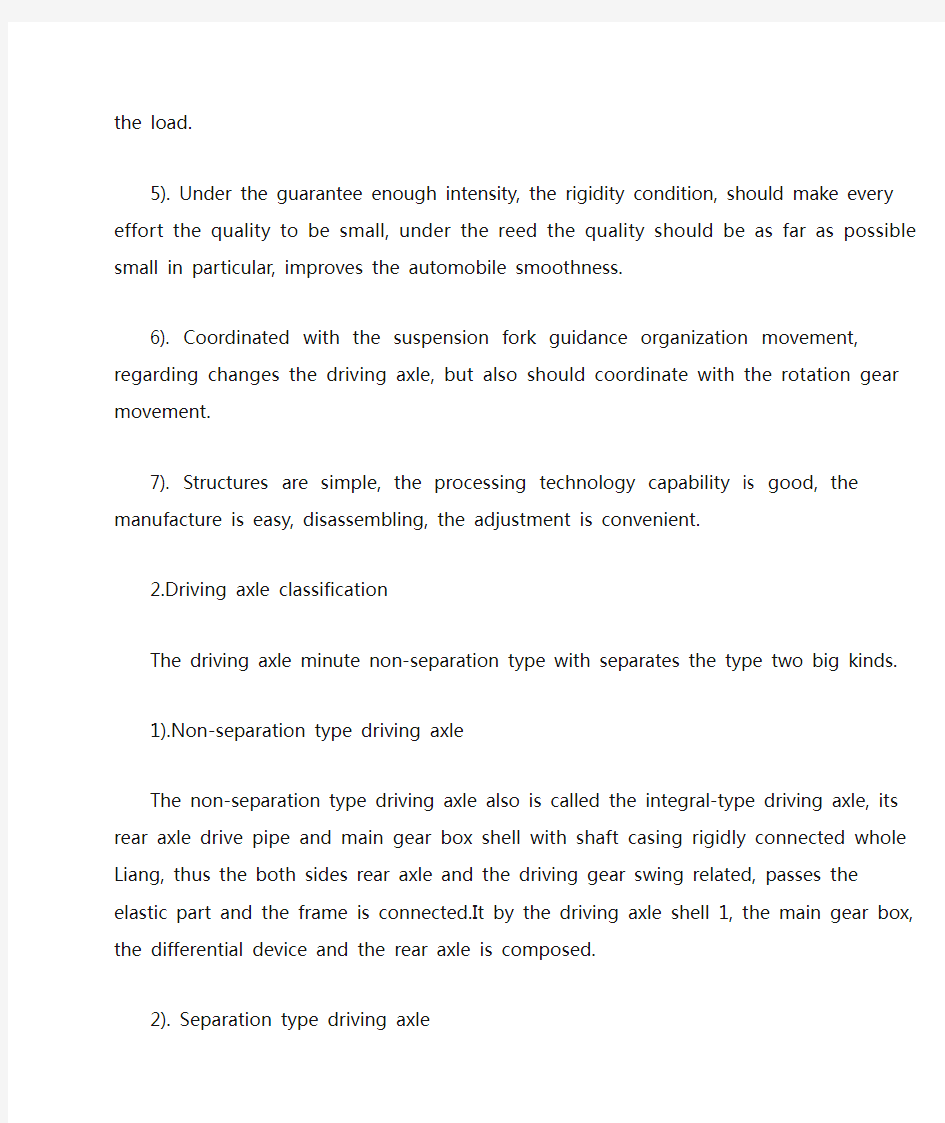
As the bearing cage rotates, read the value 7. indicated on the scale. Preload normally is specified as torque re-8. quired to rotate the pinion bearing cage, so take a reading only when the cage is rotating. Starting torque will give a false reading. To calculate the preload torque, measure the 9. diameter of the bearing cage where the cord was wound. Divide this dimension in half to get the radius. 10. U se the following procedure to calculate the bearing preload torque:Standard. Pull (lb) 3 radius (inches) 5 preload (lb-in.)or Preload (lb-in.) 3 0.113 (a conversion constant) 5 preload (N .m) Install the yoke, flat washer, and nut. Tighten 6. the nut snugly. Tap the end of the input shaft lightly to seat the bearings. Measure the input shaft endplay again with 7. the dial indicator. If endplay is still incorrect, repeat steps 3 through 7. With the endplay correct, seal the shim pack 8. to prevent lube leakage. Then torque the i nput shaft nut and cover capscrews to the correct value. 24.5 A XLE ADJUSTMENTS AND CHECKS This section introduces the differential carrier adjust-ments, checks, and tests that the truck technician must be capable of performing; some have been r eferred to previously in the text. For the most part, the procedures described here are general in nature. The truck technician should refer to OEM service l iterature for specific procedures.PINION BEARING PRELOAD Most differential carriers are provided with a press-fit outer bearing on the drive pinion gear. Some older rear drive axles use an outer bearing, which slips over the drive pinion. The procedures for adjusting both types follow. Press-Fit Method Adjustment To adjust the pinion bearing preload using the press-fit method, use the following procedure: Assemble the pinion bearing cage, bearings, 1. spacer, and spacer washer (without drive pin-ion or oil seal). Center the bearing spacer and spacer washer between the two bearing cones (Figure 24–49). When a new gear set or pinion bearings are 2. used, select a nominal size spacer based on OEM specifications. If original parts are used, use a spacer removed during disassembly of the drive. Place the drive pinion and cage assembly in a 3. press, with the gear teeth toward the bottom.Apply and hold the press load to the pinion 4. bearing. As pressure is applied, rotate the bearing cage several times so that the bear-ings make normal contact. While pressure is held against the assembly, wind 5. a cord around the bearing cage several times.Attach a spring scale to the end of the cord 6. (Figure 24–50). Pull the cord with the scale on a horizontal line. FIGURE 24–49 Assembly of the pinion bearing cage. (Courtesy of Dana Corporation) FIGURE 24–50 Cage in press to check bearing p reload. Sleeve must apply
土木工程专业外文文献及翻译
( 二 〇 一 二 年 六 月 外文文献及翻译 题 目: About Buiding on the Structure Design 学生姓名: 学 院:土木工程学院 系 别:建筑工程系 专 业:土木工程(建筑工程方向) 班 级:土木08-4班 指导教师:
英文原文: Building construction concrete crack of prevention and processing Abstract The crack problem of concrete is a widespread existence but again difficult in solve of engineering actual problem, this text carried on a study analysis to a little bit familiar crack problem in the concrete engineering, and aim at concrete the circumstance put forward some prevention, processing measure. Keyword:Concrete crack prevention processing Foreword Concrete's ising 1 kind is anticipate by the freestone bone, cement, water and other mixture but formation of the in addition material of quality brittleness not and all material.Because the concrete construction transform with oneself, control etc. a series problem, harden model of in the concrete existence numerous tiny hole, spirit cave and tiny crack, is exactly because these beginning start blemish of existence just make the concrete present one some not and all the characteristic of quality.The tiny crack is a kind of harmless crack and accept concrete heavy, defend Shen and a little bit other use function not a creation to endanger.But after the concrete be subjected to lotus carry, difference in temperature etc. function, tiny crack would continuously of expand with connect, end formation we can see without the
土木工程外文文献翻译
专业资料 学院: 专业:土木工程 姓名: 学号: 外文出处:Structural Systems to resist (用外文写) Lateral loads 附件:1.外文资料翻译译文;2.外文原文。
附件1:外文资料翻译译文 抗侧向荷载的结构体系 常用的结构体系 若已测出荷载量达数千万磅重,那么在高层建筑设计中就没有多少可以进行极其复杂的构思余地了。确实,较好的高层建筑普遍具有构思简单、表现明晰的特点。 这并不是说没有进行宏观构思的余地。实际上,正是因为有了这种宏观的构思,新奇的高层建筑体系才得以发展,可能更重要的是:几年以前才出现的一些新概念在今天的技术中已经变得平常了。 如果忽略一些与建筑材料密切相关的概念不谈,高层建筑里最为常用的结构体系便可分为如下几类: 1.抗弯矩框架。 2.支撑框架,包括偏心支撑框架。 3.剪力墙,包括钢板剪力墙。 4.筒中框架。 5.筒中筒结构。 6.核心交互结构。 7. 框格体系或束筒体系。 特别是由于最近趋向于更复杂的建筑形式,同时也需要增加刚度以抵抗几力和地震力,大多数高层建筑都具有由框架、支撑构架、剪力墙和相关体系相结合而构成的体系。而且,就较高的建筑物而言,大多数都是由交互式构件组成三维陈列。 将这些构件结合起来的方法正是高层建筑设计方法的本质。其结合方式需要在考虑环境、功能和费用后再发展,以便提供促使建筑发展达到新高度的有效结构。这并
不是说富于想象力的结构设计就能够创造出伟大建筑。正相反,有许多例优美的建筑仅得到结构工程师适当的支持就被创造出来了,然而,如果没有天赋甚厚的建筑师的创造力的指导,那么,得以发展的就只能是好的结构,并非是伟大的建筑。无论如何,要想创造出高层建筑真正非凡的设计,两者都需要最好的。 虽然在文献中通常可以见到有关这七种体系的全面性讨论,但是在这里还值得进一步讨论。设计方法的本质贯穿于整个讨论。设计方法的本质贯穿于整个讨论中。 抗弯矩框架 抗弯矩框架也许是低,中高度的建筑中常用的体系,它具有线性水平构件和垂直构件在接头处基本刚接之特点。这种框架用作独立的体系,或者和其他体系结合起来使用,以便提供所需要水平荷载抵抗力。对于较高的高层建筑,可能会发现该本系不宜作为独立体系,这是因为在侧向力的作用下难以调动足够的刚度。 我们可以利用STRESS,STRUDL 或者其他大量合适的计算机程序进行结构分析。所谓的门架法分析或悬臂法分析在当今的技术中无一席之地,由于柱梁节点固有柔性,并且由于初步设计应该力求突出体系的弱点,所以在初析中使用框架的中心距尺寸设计是司空惯的。当然,在设计的后期阶段,实际地评价结点的变形很有必要。 支撑框架 支撑框架实际上刚度比抗弯矩框架强,在高层建筑中也得到更广泛的应用。这种体系以其结点处铰接或则接的线性水平构件、垂直构件和斜撑构件而具特色,它通常与其他体系共同用于较高的建筑,并且作为一种独立的体系用在低、中高度的建筑中。
驱动桥设计_毕业设计论文
驱动桥设计 摘要 现代工程车辆技术追求高效节能、高舒适性和高安全性等目标。前一项目标与环境保护密切相关,是当代全球性热门话题,后两项目标是车辆朝着高性能化方向发展必须研究和解决的重要课题。转向系统的高性能化是指其能够根据车辆的运行状况和驾驶员的要求实行多目标控制,以获得良好的转向轻便性、较好的路感和较快的响应性。 汽车转向系统是影响汽车操纵稳定性、行驶安全性和驾驶舒适性的关键部分。在追求高效节能\高舒适性和高安全性的今天,电控液压助力转向系统作为一种新的汽车动力转向系统,以其节能、环保、更佳的操纵特性和转向路感,成为动力转向技术研究的焦点。 本文通过查阅相关的文献,介绍了EHPS系统的结构组成和工作原理,在参考现有车型的结构数据的基础上,设计计算转向系的主要参数,确定转向器的结构参数和动力转向部分结构参数,在分析其助力特性的基础上,设计合理的助力特性曲线,并通过MATLAB作出助力特性图,同时提出一种基于车速和转向盘转动角速度的控制策略,根据EHPS系统的特点,通过AMESim和Simulink建立整个系统的模型。通过联合仿真可以得出EHPS系统比HPS系统能提供更好的助力特性和转向路感。 关键词:EHPS;助力特性;结构设计;AMESim与Simulink建模 ABSTRACT
High effective energy saving,high comfort performance and high security are thegoals of contemporary.The first goal closely concerns with environment protecting,is also the popular topic around the world.The last two goals are the important subjects must be researched and solved in making automobile high performance.To make the steering system high performance is that the system can carry out mufti-goals control according to the vehicle states and drive requirements to acquire the steering handiness,better road feeling,better anti-interfering performance and faster response. The motor turing system is the essential part which affects the automobile operation stability,the travel security and the driving comfortablet.Nowadays we pursue highly effective energy conservation,the high comforrtableness and high secure.The electrically hydraulic power steering (EHPS) taking as one kind of new automobile power steering system,it takes the power steering engineering research the focal point by its energy conservation,the environmental protection,the better handling characteristic and changes the road feeling. According to consult relevant literature, this paper introduces the structure and the principle of EHPS, bases the further study of EHPS on the structural parameter date of a certain type of the light lorry, calculates the main parameters of steering system and power steering and devises the hydraulic circuit of EHPS. On the basis of the analysis of EHPS, this paper designs a reasonable EHPS power curve, including plotting the curve with the technique of MATLAB. Taking into account the steady steering and emergency steering, it advances the control strategy plan based on speed, steering wheel angle velocity, the steering wheel torque. Based on the structural characteristics of EHPS, this paper proposed AMESIM and SIMULINK joint simulation of the entire EHPS system. Accord to the result we can know that EHPS can offer more secure handle, more saving energy and way feeling. Key words:EHPS;Characteristics of power; Structure design; AMESim and Simulink Modeling
驱动桥设计外文翻译
驱动桥设计外文翻译 驱动桥设计 随着汽车对安全、节能、环保的不断重视,汽车后桥作为整车的一个关键部件,其产品的质量对整车的安全使用及整车性能的影响是非常大的,因而对汽车后桥进行有效的优化设计计算是非常必要的。 驱动桥处于动力传动系的末端,其基本功能是增大由传动轴或变速器传来的转矩,并将动力合理地分配给左、右驱动轮,另外还承受作用于路面和车架或车身之间的垂直力力和横向力。驱动桥一般由主减速器、差速器、车轮传动装置和驱动桥壳等组成。 驱动桥作为汽车四大总成之一,它的性能的好坏直接影响整车性能,而对于载重汽车显得尤为重要。驱动桥设计应当满足如下基本要求: 1、符合现代汽车设计的一般理论。 2、外形尺寸要小,保证有必要的离地间隙。 3、合适的主减速比,以保证汽车的动力性和燃料经济性。 4、在各种转速和载荷下具有高的传动效率。 5、在保证足够的强度、刚度条件下,力求质量小,结构简单,加工工艺性 好,制造容易,拆装,调整方便。 6、与悬架导向机构运动协调,对于转向驱动桥,还应与转向机构运动协调。智能电子技术在汽车上得以推广使得汽车在安全行驶和其它功能更上一层楼。通过各种传感器实现自动驾驶。除些之外智能汽车装备有多种传感器能充分感知交通设施及环境的信息并能随时判断车辆及驾驶员是否处于危险之中,具备自主寻路、导航、避撞、不停车收费等功能。有效提高运输过程中的安全,减少驾驶员的操纵疲劳度,提高乘客的舒适度。当然蓄电池是电动汽车的关键,电动汽车用的蓄电池主
要有:铅酸蓄电池、镍镉蓄电池、钠硫蓄电池、钠硫蓄电池、锂电池、锌—空气电池、飞轮电池、燃料电池和太阳能电池等。在诸多种电池中,燃料电池是迄今为止最有希望解决汽车能源短缺问题的动力源。燃料电池具有高效无污染的特性,不同于其他蓄电池,其不需要充电,只要外部不断地供给燃料,就能连续稳定地发电。燃料电池汽车(FCEV)具有可与内燃机汽车媲美的动力性能,在排放、燃油经济性方面明显优于内燃机车辆。 这项发明通常涉及到多能源动力总成的车辆,以及,尤其是多能源动力总成,有多个电源包括电动马达来驱动的汽车轮子。混合动力电动动力系统已经被发展成为包括电机(IC)做内燃机引擎,自主经营的或者联合根据行驶条件下,国家费用的牵引电池,与电源,最有效地满足当前所产生的电力需求车辆操作。大部分电子混合动力汽车可以在市场上买到是前轮驱动车辆,只不过前轮带动起来的。混合动力电动动力系统被开发用于四轮驱动车,允许两个电机和引擎传送权力后方的驱动轮。当包装电动马达驱动后桥机组是较好的使用躺轴功率流,马达驱动单元被放在后桥中心线。这样的电的混合动力系统,然而,现在的包装设计很困难,特别是当副轴车辆传动是用来传输动力,纵向驱动轴后轴。需要混合动力电动存在的动力,在其中轴是靠电动机驱动的或的内燃机结合电机。以减少成本,电动机器将提供所有混合功能,包括电气能源的产生、电动汽车、电子发动机启动投放 提高发动机的功率,再生式制动。一个驱动器单位是混合动力电动汽车包括市场, 发动机,电动机器包括转子,副轴,齿轮组包括一个输入可驱动的连接到发动机和输出,用来传送之间权限投入与产出和生产第一速度微分导致一个录入速度超过每小时的速度输出,第一和第二驾车轴差动机构可驱动的连接到输出线时,因为传输功率和输出之间驾车轴,可驱动的行星齿轮装置连接到输出和转子,说之间权限传输转子和输出线,制作了第二速度微分导致转子速度超过速度输出。转矩反应为减速
土木工程毕业设计外文翻译最终中英文
7 Rigid-Frame Structures A rigid-frame high-rise structure typically comprises parallel or orthogonally arranged bents consisting of columns and girders with moment resistant joints. Resistance to horizontal loading is provided by the bending resistance of the columns, girders, and joints. The continuity of the frame also contributes to resisting gravity loading, by reducing the moments in the girders. The advantages of a rigid frame are the simplicity and convenience of its rectangular form.Its unobstructed arrangement, clear of bracing members and structural walls, allows freedom internally for the layout and externally for the fenestration. Rig id frames are considered economical for buildings of up to' about 25 stories, above which their drift resistance is costly to control. If, however, a rigid frame is combined with shear walls or cores, the resulting structure is very much stiffer so that its height potential may extend up to 50 stories or more. A flat plate structure is very similar to a rigid frame, but with slabs replacing the girders As with a rigid frame, horizontal and vertical loadings are resisted in a flat plate structure by the flexural continuity between the vertical and horizontal components. As highly redundant structures, rigid frames are designed initially on the basis of approximate analyses, after which more rigorous analyses and checks can be made. The procedure may typically inc lude the following stages: 1. Estimation of gravity load forces in girders and columns by approximate method. 2. Preliminary estimate of member sizes based on gravity load forces with arbitrary increase in sizes to allow for horizontal loading. 3. Approximate allocation of horizontal loading to bents and preliminary analysis of member forces in bents. 4. Check on drift and adjustment of member sizes if necessary. 5. Check on strength of members for worst combination of gravity and horizontal loading, and adjustment of member sizes if necessary. 6. Computer analysis of total structure for more accurate check on member strengths and drift, with further adjustment of sizes where required. This stage may include the second-order P-Delta effects of gravity loading on the member forces and drift.. 7. Detailed design of members and connections.